Midterm Project Individual Reflection -Emily Wright

Cup Climate – Emily Wright – Eric

The previous group project helped immensely when creating the Cup Climate. The group project created a solid definition of interaction, and this made it much easier to choose a project to make. The definition that we created was that interaction required two parties to listen, think, and then speak to each eachother. My group’s research project was the FitBox, which was an interactive work out assistant. While this was a great example of an interaction device, my partner and I wished to make a device where, while still interactive, less human input is needed in order for the device to have a purpose. The Cup Climate is similar to other cup holder that read the temperature, but the difference lies in the interaction. Other cup holders will just read the temperature of the cup, and the user must look at it, but the Cup Climate allows the user to set the preferred temperature settings, so they are alerted when their beverage has reached a certain temperature. The best example of this would be a person whose coffee is always too hot. Once the cup is in the holder and they set the temperature to the temperature of their perfect cup of coffee; the cup constantly reads the temperature, and alerts the user once the coffee has reached the perfect temperature. This is much more useful than having a holder that simply reads the temperature because the user can forget about their drink and the Cup Climate will remind them once their drink has reached the perfect temperature. This would be ideal for those who work in a place where they can have the Cup Climate nearby because they have to hear the tone and see the light flash. An office setting would be ideal. The users get to focus harder because they do not have to read the temperature of their drink, and therefore get more work done. This would also be a great tool for children to use. The Cup Climate could prevent kids fro burning themselves on hot drinks, or it could tell them to drink their cold drink before it gets warm.

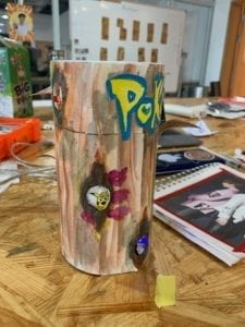
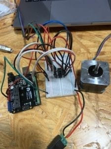
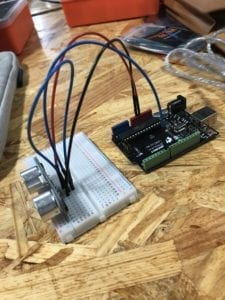
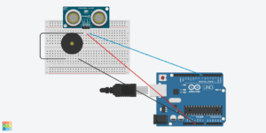
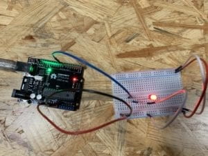
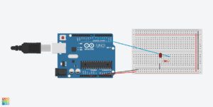
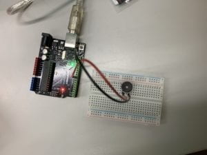
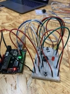
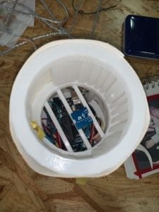
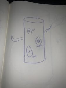
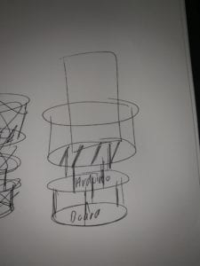
Our original design for the Cup Climate was too have it be a coaster, but we decided to go with the taller design so it would look more visually appealing. The design makes it simple to know where to place the cup because there is only one opening the the cup can go into. 3-D printing the skeleton of the cup holder was the best option because the structure had to able to hold a cup full of liquid. The  structure was built in a tiered way, so we could fit the breadboard and the Arduino all inside of the container. We chose a red, yellow, and blue LED and then placed the lights in a descending order in order to better express what the temperature is.  We originally wanted the middle temperature to be represented with a green LED, but it was too dim, so we opted for a yellow LED. The yellow LED worked out well because to make it more visually appealing, we wanted to give it a theme, so we chose Pokemon. Pokemon was the best option because we could coordinate the temperature to different Pokemon. Charmander (orange red) was hot, Pikachu was medium (because of the yellow LED), and Squirtle (blue) was cold. We made the characters and the tree were made from paper. This was the easiest option, but it would have been better if we used a thicker material or 3-D printed the tree design, so it would be sturdier.

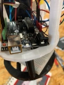
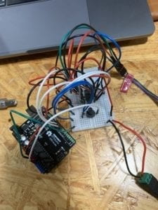
After deciding on making a taller cup holder rather than a coaster, we stayed with our design consistently. We unfortunately we were not able to have all of the components of the design printed for user testing. This meant that the Cup Climate did not look anywhere near the final product. We received many suggestions, but the main ones that we acted on were to make it look nicer and to add some other kind of stimulation. During user testing all we had were the LEDs lighting up when the temperature changed. These two suggestions definitely added to our project. Sound made the output from the holder much more interactive, and we wanted our project to look nice. We had a very hard time when we were coding our holder. The coldest temperature’s LED would not light up, and when we added the buzzer in, there was a delay on the entire program. Fortunately, with help, we were able to fix the issues. We learned how to use the state function in order to make the buzzer work. This meant that we had to declare each temperature range as a state. Then we had to have the tone sound when the state(temperature range) changed, but not sound when the state didn’t change. After implementing these changes the Cup Climate worked perfectly, as we did not have any problems with the circuit. The one final issue was attempting to fit all of the wires into the 10cm radius that the holder had, but after some stuffing, we made it fit. 


Conclusion

When creating this project, our main goal was to create a device that was still interactive, but did not require the users full attention at all times. To do this we had to make sure that the device followed the understood definition of interaction; two parties listening, thinking, and speaking to each other. I think the Cup Climate aligns with this definition of interaction very well. It “listens” to the temperature of the cup, “thinks” about if a state has changed, and when the state does change it “speaks” by lighting up and buzzing. The audience understood to put the cup into the holder easily, and interacted further when the state changed and they saw the light and heard the buzzer. When the state changed, they were prompted to grab the cup to see the temperature. This kind of interaction is simple, so to improve this I would add more components that the user could interact with. This could be in the form of adding music to fit the theme, or adding more lights so the state change is better seen. With these additions more coding would be involved, but from the many failed codes that appeared in the making of this project, I think I will be much better equipped to create more complicated codes. The ideas that came from this project will only breed bigger and more useful products. Overall, I learned not only the process of physically creating an interactive project, but I also learned the digital process as well.  project was valuable to students because of the obvious task of creating an interactive project. Learning about interaction is important, but implementing it into a project breeds a better understanding.

Recitation 4: Drawing Machine

Intro

During this recitation we were asked to control a stepper motor by the use of an H-bridge. The purpose of this was to familiarize us with the function of each prong on the H-bridge, and also introduce us to the way a stepper motor works. In addition, we also had the task of coding the stepper motor, so it could work as a drawing machine. 

Materials

For Steps 1 and 2

1 * 42STH33-0404AC stepper motor
1 * L293D ic chip
1 * power jack
1 * 12 VDC power supply
1 * Arduino kit and its contents

For Step 3

2 * Laser-cut short arms
2 * Laser-cut long arms
1* Laser-cut motor holder
2 * 3D printed motor coupling
5 * Paper Fasteners
1 * Pen that fits the laser-cut mechanisms
Paper

Step 1

Building the circuit with the H-bridge was very easy. The only issued that occurred was when I accidentally connected the wires to the wrong end of the H-bridge; I thought the semi-circle went on the bottom of the circuit. All I had to do was turn the H-bridge around to face the other way and the problem was solved! We were able to use a sample code, so there were no issues when coding the stepper motor to run. 

Step 2

Adding the potentiometer into the circuit was a fairly simple process because it was completely separate of the rest of the circuit. It was the same as all of the other times we had used it in the past. It also helped that we had built a similar circuit in class the day before, I had a hard time with the code that allowed this circuit to run. We were given the example code, but we had modify the number of steps to 200. This was because the stepper motor is a 200 step motor, and having the code include 200 steps would make the motor as accurate as possible. To change the number of steps, I used the map function, and the code worked perfectly. The potentiometer could be used to turn the motor!

Step 3

Step 3 was to create a drawing machine with our partner’s and our motor. Building the drawing machine was very easy, but we had trouble with getting our motors to work properly. Despite working previously, both of our motors had issues. My motor was running by itself, even though I was not turning the potentiometer. My partner’s motor would not run at all. We were not able to completely solve the problem due to class ending, but we could conclude that something within our circuits must be wrong. This is because the code had worked before, and the motor turned when the potentiometer was used, but now it didn’t work. Nothing in the code had changed, so we must have messed something up within each of our circuits while we were building the drawing machine. 

Question 1 

I think it would be very fun to build machines like the one we built during this recitation. It would be very cool to make a really big version of this, kind of like an extra large Etch-a-Sketch. To do this a larger motor would be necessary, and it would need a larger number of steps so it could be as accurate as possible. It would be great to have this despite all of the digital art that we have today. The physical creation of art is an important tradition that we should keep a hold of. It allows us to combine the old history of art with contemporary art and technology.Image result for etch a sketch

Question 2

I found Nicholas Stedman’s Blanket Project to be very interesting. It is supposed to be a completely autonomous blanket that seeks to find human contact and serve as a “subtle companion”. This machine is very different compared to the drawing machine we built during recitation. The first and most obvious difference is that it does not need a human to navigate it at all times. The drawing machine required us to turn our potentiometer in order for it to draw. Stedman most likely uses many different motors, so the blanket can navigate to the best of its ability. 

Group Project Individual Write Up -Emily Wright

Definition

At the beginning of this semester, we were introduced to many situations where interaction between ourselves and technology took place. From experiencing these different interactions, I have been able to shape my definition of interaction. Interaction is one party initiates a communication with another party. Following this initial stimulus, the second party must take the time to react and synthesize a response to the first party’s effort. This act of “listening, thinking, and speaking” is what makes an interaction interactive. (Crawford 3)

Projects

Our group went through a number of ideas that we thought would be useful in everyday life. We finally settled on an interactive workout machine. We had a number of inventions that inspired our machine, but the main ones were the Fitbit and the PainPod. Both of these projects have senses of being interactive, and we used these characteristics within the FitBox. We gained the most inspiration from the Fitbit because it has the most interactive features. A person puts on their Fitbit and then goes on with their day. The Fitbit records fitness information until the person wearing it taps the sides, and then the Fitbit thinks and responds with the person’s fitness information at that moment. This represents our definition of interaction very well; the Fitbit is accepting stimulus, counting and storing the information, but it lacks the ability to respond. We wanted a better version of this interaction, one that provided similar services, but had a more interactive response.

The PainPod is a helpful project, but it lacks most of the interactive properties that we wished to include in our invention. We liked this project because the idea of stopping pain before injury is something that an ideal workout machine could do. Despite the inspiration, this device lacks the basic principles of interaction; listening, thinking, and speaking. When you applying the patches, they immediately begin blocking pain signals, not matter if the person is in pain at that moment or not. This is not the same as a device listening to the stimulus given. If the device cannot listen to stimuli, then it cannot think and respond because it has no information to relay. 

The FitBox

The central idea of the FitBox was to simulate a personal trainer, and all of the interactions that they can provide in real life. The FitBox has (as of now) two different modes, one is a form correction function, and the other is a motivational function. Both follow our group’s definition of interaction. During both workouts, the user begins the workout, and the machine begins its process. The FitBox scans the user, and then follows throughout the workout to detect issues and to provide motivation when the user has none. This is the beginning of the interaction, the user’s movement provides information for the machine to scan. The machine then assess this information, and responds when there is an issue with form or motivation. When a problem is detected it responds with a hologram, so the user can easily see and fix the issue. The process of the FitBox assessing what the user is doing, searching for issues, and sending out a hologram is a perfect example of a machine listening, thinking, and speaking. 

Works Cited

Crawford, “What Exactly is Interactivity,” The Art of Interactive Design,  pp. 1-5.

https://thepainpod.com/pages/pain

Recitation 3: Sensors Emily Wright

Intro

During this recitation, we were asked to create a circuit that included a sensor, and later to have an output powered by the sensor. This was so explore the interactive properties that sensors provide within a circuit, and also to challenge us to integrate two different codes together into one. 

Materials

1 Breadboard

1 Arduino Uno

1 Buzzer

1 USB A to B cable

1  Ultrasonic Ranger

Jumper cables

Building the Circuit

Building this circuit was a fairly simple process. My partner and I decided to use the ultrasonic ranger as our sensor. We began by building the circuit without the buzzer on the output. We also used the code provided on the website. This was successful, as we saw the distance change on the serial monitor as we moved closer and further away from the sensor. After that, we successfully integrated a buzzer into our circuit, but we ran into trouble with our code.  The buzzer would not make any noise. While we had the code for the ultrasonic ranger and a simple code for the buzzer, we had a hard time finding the proper way to combine the two. Finally, after asking for help, we were able to get the buzzer to make a sound. To make it more clear, we added another tone when the sensor read a certain distance. From this, I learned where some common mistakes come in when trying to combine different codes. This includes forgetting to paste something in, or not include a space in the correct place. 

Without the buzzer

With the buzzer

The schematic

Question 1

During our recitation exercise, we made a circuit that is similar to an alarm system. The sensor reads distance, and when a certain distance is passed, the buzzer makes noise. A similar circuit could be used with a louder siren to be a home security system. 

Question 2

Code is similar to a baking recipe. When baking, it is important to have precise amounts of the ingredients, in a specific order. Code is similar, in that, it has to be precise (ex.) correct punctuation and spelling) and it a certain order (ex.) setup and then loop). 

Question 3

Computers impact human behavior directly. Computers have helped make human life much more efficient by providing shortcuts for things that otherwise would take much longer. A great example of this is autocorrect on cellphones. Autocorrect has cut out the need to know exactly how to spell words, as long as you’re close you’re fine. Computers have causes humans to adapt to having help, and in turn has caused us to become more efficient because we are able to focus on other tasks. 

Recitation 2: Arduino Basics Emily Wright

Introduction

During this recitation, we were given our Arduino kits. We were asked to make three different circuits, which all demonstrated different types of code. This activity was to let us explore our Arduino Kit, and to continue to create more advanced circuits. 

Materials

1 * Arduino Uno
1 * USB A to B cable
1 * breadboard
1 * buzzer
2 * LEDs
2 * 220 ohm resistors
2 * 10K ohm resistors
2 * pushbuttons
A handful of jumper cables

2 * arcade buttons
1 * Multimeter (optional)

Circuit 1

The goal of this circuit was to build and code an LED to fade on and off. This circuit was very simple to build, there were no issues. Copying and pasting the code made it very easy for it to function correctly as well. 

Circuit with the light fully on

The schematic

Circuit 2

This circuit was even simpler that the first. We had to make a buzzer sing a small tune. Aside from the fact that I forgot to take a picture during recitation and had to rebuild it, there were no issues. 

The buzzer in action!

The schematic

Circuit 3

This circuit was significantly more complicated than the previous two. The goal was to build a circuit that would allow my partner and I to play a game where we press the button as many times as we can in ten seconds.  Everything went smoothly until we reached the end of the game, and the winners LED did not light up. After some investigation we discovered that we had switched the input and output of the LED, and this caused the problem. We switched it back, and then the circuit worked perfectly. Next time, I will make sure to double check which is the input and which is the output. 

Our lovely circuit

The schematic

Question 1

It is impossible to go a day without technology here in Shanghai. Everyday I interact with hundreds of types of technology. “Physical Computing” says, “interaction is an iterative process of listening, thinking, and speaking between two or more actors”. The QR code is a great example.A major, and possibly the most important example would be using my phone to pay for things on WeChat. The scanner reads my QR code and sends a signal to what ever screen the cashier is using to announce that I have paid.

Question 2

We use a 10K resistor in order to have the correct voltage flow through the push button. If a different resistor was used, then the buzzer would have too much or too little voltage flowing through and it wouldn’t work properly. 

Question 3

If I had 100,00 LED lights I would make a “mood” jacket. I would attach the LEDs to a jacket and put heat sensors within it, so the colors would change as a person’s body heat changes. I would wear it, but anyone who wanted to try it out would be more than welcome to!