Final Project Update

Project: Swapr Clothing Exchange Application

Partner: Sara Bruszt

I created an online survey and we received 30 responses from people all around the world. They responded positively and gave us some great input. The main points they mentioned were issues they had with other clothing exchange applications (shipping and chatting system). A very interesting, and somewhat unexpected response, was that some individuals said that they would not mind involving money if either person thought the trade would be unequal. Another interesting outcome of the survey is that a lot of people were excited to meet people in there area with similar style/taste in clothing as them for future trading. 

Sara created a paper prototype and started designing the interface. I created the logo. We are working on a pitch presentation for the final as well. On top of interface streamlining, we have also been thinking of how to make the interactions with the app simple, and enjoyable (gratification responses from matching being met with firework animation or confetti). 

Moving forward, we are going to continue creating the paper prototype for user testing on Wednesday as well as the presentation. 

Considering we are also applying for the NYUAD startup program with this assignment, we are also looking into financing methods.
Recitation 2: Arduino Basics by Dominick Nardone

Partner:  Nate Hecimovich 

Circuit 1 – Fade: 

Using the analog pins on the arduino, marked with ~, we were capable of fading an LED. This was a relatively simple circuit, requiring only two jumper wires, a 220 ohms resistor, and of course, an LED.

Circuit 2 – Tone Melody:

This was also a simple circuit, requiring only two jumper wires and a speaker. Although, the coding was more complex, requiring assigning notes to frequencies, something that we would have been incapable of doing if it was not provided for us. 

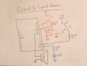
Circuit 3 – Speed Game:

Schematic:

Video: 

With the understanding of the simplicity of circuits 1 and 2, Circuit 3 was not that difficult to put together. This is definitely our first case of circuit spaghetti, but altogether was a fun project. In my opinion, it could have been approved by freeing up some space with the use of the arcade buttons that we soldered in the first week recitation. 

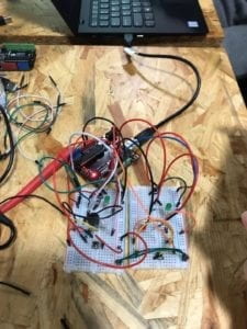
Circuit 4 – Four-Player Speed Game:

We attempted to replicate what we did for the two player game, making it a four player free-for-all extravaganza. Although we had the circuitry down, Tom worked quickly to attempt to adapt the code to work with four players. Sadly, we ran out of time before he was able to put all of the conditionals into the code. 

Question 1:

As a gamer, most of my interaction with technology revolves around pointing and clicking with a mouse, or through the use of an Xbox controller. Yet, my interaction with video games tend to result in interaction with other individuals through these games, whether through in-game chat, or third party clients like Discord. Considering the speed game we created this week, I would say the interaction is very minimal and basic. The only interaction that occurs is one of our LEDs light up, notifying both players, which was sadly always Nate, that they have the quicker thumbs. Although this interaction is simple, it still has a lot of connotations behind it, which is why I would define interaction as any simple exchange of meaningful information. 

Question 2:

If I had a 100k LEDs, I would simply hang them from the ceiling of a big, dark room and let them go off at varying intensities, rates, etc. It may be similar to the clear sky at night, something we don’t get much of in Shanghai, or may look like something entirely different. It would be entirely up to the person consuming the view.

Recitation 1: Electronics & Soldering – Dominick Nardone

Components:

  • Breadboard – The breadboard acts as an interface to connect pieces of a  circuit. 
  • LM7805 Voltage Regulator – Voltage regulators maintain the voltage input. This is important because most components within a circuit can only operate within a certain range of volts. 
  • Buzzer – The buzzer is a device that makes a noise as an output.
  • Push-Button Switch – A push-button switch closes the circuit when pressed. push-button switches act as a good input for initiating a circuit.
  • Arcade Button – Same as a push-button switch, but fancier.
  • 220 ohm Resistor – 220 ohm resistor is used to limit current in a circuit. In the circuits we did, the 220 ohm resistor is used to limit current that goes through the LED, preventing the bulbs from burning.
  • LED – LED is a light emitting diode. In circuit 2 and circuit 3, the LED acted as an output.
  • 100 nF (0.1uF) Capacitor – a capacitor stores energy to be used once the energy stops flowing, like in the flash of a camera. In circuit 3, a capacitor was used to stabilize the flow of energy for the dimming light. 
  • 10K ohm Variable Resistor (Potentiometer) – The variable resistor is a dial that allows the user to restrict the amount of electrical current flowing through the circuit. In circuit 3, the potentiometer was used to variate the amount of current flowing to the led, allowing us to adjust the brightness.
  • 12 volt power supply – The source of power for the circuit.
  • Barrel Jack – The barrel jack is the connecting apparatus from the source of power (the outlet) to the arduino. 
  • Multimeter – The multimeter is a useful tool that allows you to do a plethora of things, from identifying connections, to measuring the ohms, current, and voltage of specific components.
  • Several Jumper Cables (Hook-up Wires) – Wires connect electrical components and provide a path for the circuit. 

Images/Videos:

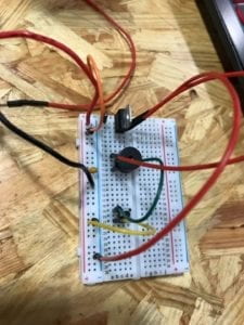
Circuit 1 – Doorbell:

At first, the voltage regulator was incorrectly placed, resulting in an incomplete circuit.

After realizing our mistake with the voltage regulator, the circuit was complete and the sounds were lovely. This did require a new voltage regulator, due to the fact that our misplacement of the first one resulted in a burnout. 

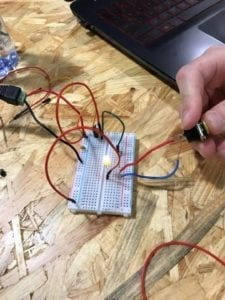
Circuit 2 – Lamp:

Now that we had a complete understanding about how to use the voltage regulator, and our freshly soldered button, we were very quickly able to assemble the second circuit, producing light.

Circuit 3 – Dimmable Lamp:

Question 1:

The process of completing these circuits definitely included interactivity. In our first circuit, we incorrectly placed our voltage regulator, resulting in an incomplete circuit. Thus, when we tried to interact with the circuit by pushing the button and hoping to hear the doorbell, we received zero feedback. This lack of interaction notified us that something was wrong, and once we realized that our voltage regulator was misplaced, we were able to correct that issue and receive the feedback we were expecting. Also, in the third circuit, the creation of the dimmable light, our interaction with the variable resistor resulted in feedback, specifically the light would dim when we increased the resistance, and would be brighter when we lowered the resistance. 

Question 2:

Interaction Design and Physical Computing can provide disabled individuals with a medium for doing what was once impossible. In Zack Lieberman’s, we see how he used simple hardware and some software to allow a severely disabled graffiti artist be able to produce art once again. Similar technology has also been developed to allow disabled individuals to be able to play online games. One example of this is in the online point and click based game Runescape, where interaction design and physical computing were used to provide these individuals with a medium for playing the game, and being capable of playing the game to the point where they can do even the most difficult content that very few can do. We have a very interesting future in store.