Midterm Project Documentation – Celine Yu

Project: Skee-ball 

Partner: Kenneth Wang

Documentation By: Celine Yu 

Instructor: Young 

Individual Reflection

Context and Significance:

The Group Research Project that my team and I created was that of a sign-language interpretation device that was to be disguised within skin-adhering gloves. The gloves at the time, fit into my personal definition of interaction, which depicted as a relationship between multiple subjects who affect one another as they each provide the other with information, and in return, receive feedback. Simply put, it is a dynamic process consisting of constant input and output from not just one actor, but several. My definition of interaction was solidified as I continued to research about our project, most specifically when I understood the interaction between not only the user and the gloves but also the user with his/her surroundings following the implementation of the gloves in their lives. The user would provide the gloves with information through sign-language, allowing the gloves to provide feedback and ultimately, input in the form of audible words. This input would be received by the user’s surrounding, which would then manifest a reaction and form feedback in return to the user. This is where I pitched the idea of recreating a skeeball machine to Kenneth. He was confused at first, for he had never heard nor played a game of skeeball with his friends down at a local arcade, news that caught me significantly off guard. As I continued to show him pictures of the nostalgic arcade game and explaining to him the main objective of the game, I began to realize just how different our cultural backgrounds were from each other. This factor is what fueled my desire to create it for our midterm project, a passion that my partner, Kenneth, wholeheartedly agreed with. We wanted to put our own spin on the already long existing arcade game, by making it somewhat portable. Original skeeball games all come as large machines, making it impossible for a user to take the experience home with them. I kept this factor in mind when conceptualizing the design as it inspired me to create measurements that would be deemed suitable for such a portable machine. What we wanted to contribute to the world of the arcade, or at least, the world of skeeball, was to introduce the game to all cultures and individuals around the world. Just like how Kenneth was unaware of the game’s presence in the world, there must be numerous amounts of people who also are not aware of the nostalgic arcade phenomenon. Together, Kenneth and I wanted to create this skeeball machine as our midterm project so that we could tie together even more cultures and individuals by sharing with one another, a stress-relieving game that ensures fun and laughter.

Conception and Design:

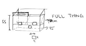
From the beginning, we knew that we wanted the final product to stimulate a set of emotions from within the users, whether it be competitiveness and or happiness. To achieve this response, we implemented the decision for players to verse one another simultaneously. We also thought the response could be achieved through a sense of adrenaline rush, which is why we added the design of a slope that automatically returns the ball to the user within the next second. In addition to these designs, we also considered the addition of variables that would trigger certain senses, most specifically, tools such as LED lights and buzzers. When it came to materials and roles, we split them into 2 main categories: Design and Arduino. The designing portion consists of elements that play a part in how the machine will look and function. This category spreads to matters of both interior and exterior design, which is the factor that I was responsible for. I used my iPad to first, sketch out the main idea of the skeeball machine, making sure to draw in it precisely with the notations of specific measurements that we thought would be perfect for the project.
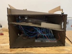
Following my sketch, and approval from my partner, Kenneth, we began to design the box through a website known as Makerbox. We were aware of this program due to the lectures and used it to our advantage. We set the box’s sizes and selected the teeth binding layout that would piece together the boards after it was laser-cut. The laser-cutter was the best source for our project, as it provided us access to hard material that would act as the exterior of the design. It was sturdy and was believed to sustain any damages made to it during usage. These factors are what placed the hard-board above simple loose-cardboard, and ultimately, the best material we could possibly use for the exterior. As for the interior, I decided that loose-cardboard would be the most befitting material to use as it was fairly flexible and could easily be manipulated by hand, making it easier for me to create a slope with scissors.
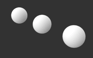
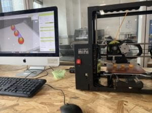
Aside from the box, we also printed out a number of 3D balls for the users to play with. We had originally believed that marbles would work just as well, but the main factor that persuaded us into using 3D fabrication for the project was so that we could be hands-on with the entire project. We wanted to be able to utilize as many skills and techniques we’d learn in the past few weeks, which is why we opted for the 3D printed balls instead of basic marbles.
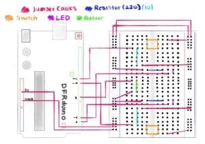
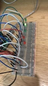
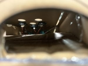
Moving on from the Design portion, we have the Arduino side, the category in which Kenneth was placed in charge over. For the Arduino, we mainly used the components that originated from our Arduino boxes, such as jumper cables, buzzers, resistors, etc. To accompany our advanced code, we also borrowed a list of items from the IMA supply room, most specifically: extended breadboards and a total of 6 sensors (infrared and ultrasound). The extended breadboards, as Kenneth stated, were borrowed so that he could have ample space to work with, and not have to be restricted to a tiny board. Kenneth believed that the infrared sensor would serve as the best instrument for our project. Its swift ability to calculate distance compared to its rival, the ultrasound sensor proved that it was the most fitting sensor, as we required an instrument capable of catching the mere second fall of the 3D ball through the hoops. However, due to lack of stock, we were only provided access to 4 infrared sensors, indicating that we had to use two ultrasound sensors. This significant factor created many difficulties for the fabrication process, both in regards to the code as well as the physical attachment to the interior of the skeeball machine.
Fabrication and Production

When it came to designing the actual box after Makerbox, I got to work with the Illustrator application. I opened multiple duplicates of the laser cutting template provided in class, and for the most part, utilized the curvature tool, pen tool, selection tool, text tool, ellipse tool, eyedropper tool and selection tools to create the overall design. I created curly lines that connected around the left, right and back panel of the box, making it seem like one single line that wraps the machine in a continuous fashion.
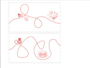
Then, on the front panel, I used the text tool, ensured that the text was the correct shade of red, and typed the quote “Sometimes, all we need is a little fun,” one of the main inspirations behind our project.
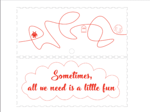
Continuing onto the top panel, I followed the sketch I made on my iPad and began making changes with the two pen tools, making circles and rectangles with them that would either be laser cut or engraved during the fabrication process. All of the formatting and measurements were quite difficult to determine as I was constantly forced to convert values between in, pt, and cm.
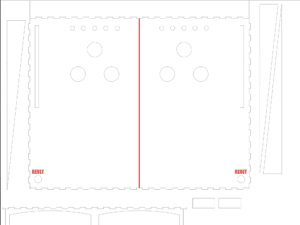
In total, I had scheduled around 4-5 sessions with the fabrication lab, in hopes of getting the measurements as close as possible to our original design. We ran into various problems that significantly stumped me as the main designer. There were times where the panels didn’t together, or wasn’t cut through entirely and or the measurements were incorrect.
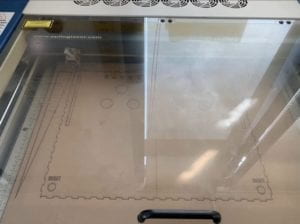
The fabrication process of the physical design was significantly energy draining, just as the coding process. The coding portion was mainly watched over by Kenneth, which is why I believe that I do not have the right nor the ability to speak of the difficulties that may have surfaced during the process of production. To understand more about this portion and Kenneth’s role, please refer to his personal documentation post.
 

User testing was a very pleasant experience to both Kenneth and me, as we received a variety of suggestions, allowing both of us to realize the importance of having other users test our product. We were provided new perspectives on the project where we were once blind sighted about, and were provided constructive criticism that significantly influenced our future production decisions. We learned of the difficulty of retracing the ball back to the user, the difficulty of understanding the objective of the game, and also the difficulty behind knowing where to even start playing from.

2 <–  user testing video

With their suggestions, we made various adaptations to our project over the following weekend. I added instructions to the product with signs and keywords that seemed sufficient enough for the user’s understanding and glued them into a position that would not be disregarded. I also added extra barriers in the playing area, so that the ball could use the sides as rebounds. When it came to the final product, I truly do believe that the adaptations I made based off of the user testing experience were effective and overall, did improve our project significantly.
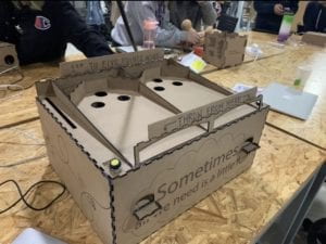
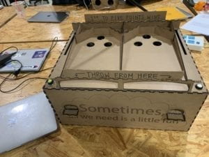
Conclusion:

Once again, the main goal of the project was for Kenneth and I to create a working skeeball machine capable of relieving stress and bringing together segregated cultures through forms of interaction. The audience interacted with our project just as planned, meaning that they formed an interactive relationship with the machine. While players attempt at scoring goals (input), the machine provides players with feedback in the form of LED light indication and sound effects. In return, the players’ natural competitiveness is stimulated while a sense of pleasure and satisfaction runs through their bodies. This cycle of interaction between the audience and our project parallels that of Kenneth’s and my definition of interaction. Together, we depict it as a dynamic process where multiple subjects affect one another through a cycle of input and output. If we were to attempt this project with more time and an even more expansive set of skills, I would definitely suggest that we add a digital scoreboard that also provides point indication to the players, another form of feedback to the users’ input. This will instead, provide validation of victory through numbers and neither lights or sounds, stimulating another one of the players’ senses. We could also consider adding a sound effect that indicates the functionality of the RESET button, as to most users, it was difficult to determine if whether or not the button had been set off. Kenneth and I could also consider 3D printing even more balls, possibly some with forms of deformations that will change the difficulty of the game to partner an increase in inclination of the top panel. Overall, from this project I can honestly say that I’ve learned a lot about the importance of patience and thorough planning. When working on the design, I tended to rush through certain steps such as calculating measurements and laser cutting boards as a means of meeting deadlines, which ultimately resulted in boards that were below my own as well as Kenneth’s expectations. Keeping calm and taking my time to complete my tasks efficiently is my main focus for the next project, this way, I can save material as well as leave ample time for myself to finish other tasks and to help Kenneth with his part of the project. Apart from this lesson, I am extremely happy and thankful for the accomplishments I’ve made with Kenneth as my partner. I realized how important teamwork is when completing a project as extravagant and advanced as our skeeball machine. Both of us were more than willing to stay late at night in the IMA classrooms in order to perfect our project, a characteristic I am truly thankful that we share. To answer the questions of “so what?” as well as “why should anybody care?” to end my report of the midterm project, I wish to bring attention to the diversity of our school. NYU Shanghai is a community that values diversity and is based upon the very grounds of assimilating cultures by having its students share their experiences with one another. Kenneth and I believe this is an aspect that we wanted to present to users while placing a fun little spin that will act as a stress reliever to students. The final product will not only allow users to let loose but also teach them about other cultures and experiences, as sometimes, all we need in life is a little fun in our lives and a little knowledge to get us through it all.
Recitation 4: Drawing Machines, Celine Yu

Date of Recitation: March 16, 2019

Documented On: March 17, 2019 

Partner: Arthur Gu 

Reflection:

The objective of Recitation #4 was to create a working drawing machine with the help of an H-bridge to assemble the circuit. I finished the first two exercises by myself and proceeded to join Arthur for the third and final step of the recitation. Despite being informed of the possible damages that may occur during the exercise, I made the final decision to work on my own laptop for easy accessibility and time efficiency. This time around, I felt much more confident in my understanding of the Arduino process and its mechanics, but nonetheless, I still required assistance at certain points of the exercise.

Step 1: Build The Circuit

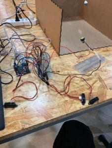
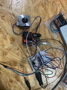
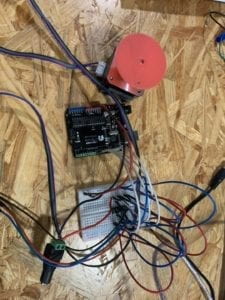
The first step was the most straightforward one out of the entire exercise. I placed the provided H-bridge onto the breadboard, ensuring that the bridge’s half circle icon faced the top of the board. While doing so, I also made sure to position the component in the middle of the breadboard knowing that each pin needed to be connected to separate parts of the Arduino board and stepper motor. Following the h-bridge, I simply followed the recitations reference in order to understand its schematics. Noting the large number of jumper cables being used, I made sure to keep the breadboard as clean as possible by using red and black to indicate power and ground respectively. (Mistake: Black should be used to indicate ground). In regards to other components, I tried my best to use a uniform color amongst them. I first connected the Arduino’s 5V to the breadboard power column and the Arduino’s GND to board’s ground column, a method I use to keep the breadboard clean as well as for easy access to either component. I follow the reference and attach each component carefully, ensuring that no mistake is made so that I could refrain from both, burning the Arduino and damaging my laptop. I interconnect the Arduino with the breadboard and H-bridge, all while leave space for the stepper motor’s pins. I then use 4 separate cables (red, blue, green and black) to attach the motor to the circuit, placing them in slots: 3, 6, 11 and 14 of the H-bridge. I then upload the pre-installed stepper_oneRevolution code to the Arduino, then proceeded to eject the component from my laptop and reattach it to the communal USB port provided during the recitation. It was a relief to see that motor began to turn upon the circuit’s attachment to its external power source. 

Step 2: Control Rotation With  A Potentiometer

The second step was a bit tricky. I went into the exercise with fear of failure and the possibility of messing up the circuit as a whole. I attached the potentiometer in the extra space below the H-bridge spreading the pins across the middle of the breadboard. I was aware that the potentiometer needed to be connected to power, ground and an analog pin, but was not sure which pin was to be attached to which. I went to my laptop and began to look through lectures slides and previous recitations, hoping to garner more information about the potentiometer. I was not unable to find my answer and so resorted to searching the internet for an answer to my confusion. When Google also failed to provide me with a solution, I decided to ask for help from one of the teaching assistants. I informed her of my confusion and she showed me while pointing to the potentiometer which pin was which. I learned that the single pin on one side needed to be connected to analog, whereas the remaining two needed to be connected to both power and ground, on this side, the order did not matter. I quickly connected the potentiometer with the Arduino’s A0 slot with a white cord and continued to attach the remaining pins to the power and ground columns of the breadboard. After I implemented the potentiometer into the circuit, I went straight to work on the code. I opened the MotorKnob example code and copy and pasted it into my original code. Then, following the instructions, I switched the steps amount from 100 to 200, implemented the A0 code and attempted at working with the map() function. I was still confused about map() and so asked for help once again but from a different teaching assistant. The assistant took one look at my code and knew what the problem was. She told me that I did not need to combine the MotorKnob and OneRevolution codes for Step 2, and in fact, only required MotorKnob for the circuit to work. I followed her words and quickly reopened the example code and worked from there instead. She instructed me on how to use the map() function, and with her help, I was immediately able to get the circuit working with the turn of my potentiometer.

Step 3: Build A Drawing Machine

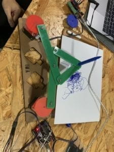
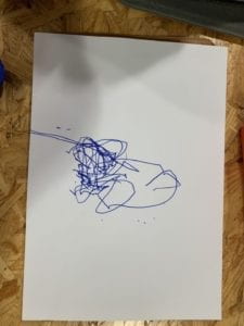
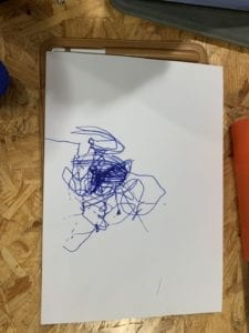
For the third and final step, I mentioned that I worked with my previous partner, Arthur, to create a cooperative drawing machine. We gathered the necessary material required and began to assemble them on top of our respective stepper motors. The mechanical arms were a bit difficult to assemble due to the clothespins’ lack of reliability. They would often fall out of their position, causing the entirety of the drawing machine to fall apart. After assembling the machine, we expected everything left remaining to be a walk in the park. This was, unfortunately, not the case. I placed the pen into position and realized that the pen did not come close to reaching the table and the paper. We could not lower the mechanicals arms in fear of them breaking all over again, and so looked for different solutions to help our situation. Arthur suggested that we level the paper upwards so that the pen would be able to reach it and draw upon it. The things surrounding us were either too tall or short in terms of height, we needed the perfect item to level the paper above the table. This is when Arthur remembered he had brought his iPad to class. He eagerly took it out of his bag placed it underneath the drawing paper. The iPad worked perfectly for our situation. Afterward, we turned on both our motors and continued to play with our potentiometers to maneuver the pen in certain directions. Soon, the motors began to emit abnormal sounds, a result that terrified both my partner and I. We realized that there was nothing we could do about the scratching and screeching, as it was due to the friction between the motor and the 3d printed motor couplings that laid upon them. Not wanting to prolong the sound effects, we tried our best to draw something on the paper. The miniature nature of the potentiometers coupled with the restrictions of the motor and its directions made it extremely difficult to attempt at creating an actual design. Due to time restrictions, we were unable to create an art piece that met either of our expectations. Nonetheless, the activity was very enjoyable and was probably one of my favorite recitations to date.

Questions  and Answers:

Q1: What kind of machines would you be interested in building? Add a reflection about the use of actuators, the digital manipulation of art, and the creative process to your blog post. 

A1: If I am to be completely honest, I have always complained about my abundant stock of long dry hair and the difficulty behind washing it, drying it and then styling it. While my short-haired friends are ready within the half hour, I have to plan ahead in order to compensate for my hour-long process. To help my fellow long-haired individuals, I would love to create, possibly in the future, an inexpensive automatic hair-washing machine. I would lie down on the machine, and wait as the sensors of the machine detect the presence of my hair and begin its work of shampooing, conditioning and possibly a head massage. I would aim for the entire process to be completed within 10-15 minutes. Once the process is finished, I will continue to dry my hair as usual and ultimately, have my hair process be cut down by 30-40 minutes. The end results would be similar to that of a salon-worthy blowout. After this first machine, I could possibly even go on to creating an automatic hair-drying machine that functions to dry my hair within seconds. This will be difficult to achieve, but would be something I’d be heavily interested in producing. Actuators, as I have learned are devices that have the sole purpose of developing a certain force and or motion that allows machines and other devices to function properly. In this recitation, the actuator being used is that of a linear actuator, the stepper motor. The motor provided the circuit with a source of rotary power, allowing me to create a fully functioning drawing machine. The art we created through this recitation originated with the digital manipulation of actuators. Arthur and I manipulated our own potentiometers and tried out best create some sort of design with our digital creation. We went into the design quite blindly, wanting to first get a hang of the controls and process before figuring out a real design and the creative process behind it. However, due to amateurism, a lack of time and the instability of the machine, Arthur and I were unable to truly create a design that we wanted, making the creative process both shallow and short. The final result was nothing but a collection of scribbles at the center of the paper, resembling that of extreme abstract art. Possibly, with more understanding of the controls and a better base, Arthur and I could reconstruct the machine at a later time, and form another attempt at producing a creative design.

Q2: Choose an art installation mentioned in the reading: “ART + Science NOW, Stephen Wilson.” Post your thoughts about it and make a comparison with the work you did during this recitation. How do you think that the artist selected those specific actuators for his project?

A2: The art installation I have chosen to reflect upon within “ART + Science NOW, Stephen Wilson (Kinetics Chapter)” is none other than Daniel Rozin’s Mechanical Mirrors: Wooden Mirror (1999-2018). Ever since I’ve learned of the definition of interaction within this course, I was always highly interested in mirrors and art installations that translated movement and or the present onto a physical platform through digital means, and not just through photography. Rozin’s installation is a perfect example for one of these interactive “photographic” moments. His project compared with the exercise I completed for recitation 4 is vaguely similar in essence. Both of them are inspired by the objective to draw and illustrate, however, while our project revolves around design, Rozin’s installation is focused on displaying reality through different material, in this case, wooden blocks. With Mechanical Mirrors, Rozin electromechanically manipulates the wooden blocks to seamlessly recreate reality. He creates a system that reads through its camera lenses, the movement of light and the transitions in grey scale values. With these values, the installation “adjusts the blocks accordingly” with hundreds of actuators. The servo motors used, ultimately grant Rozin with the manipulation and flexibility he needs. To be specific, Rozin used a total of 830 servo motors to accompany the 830 wooden blocks for this specific art installation. 

Group Project Reflection, Celine Yu

Project Title: Reveal Your Voice

Group Members: Karen Zhang, Arthur Gu, Sharon Xu, Anna 

Reflection;  My Definition of Interaction:

The term interactivity is a term remarkably ambiguous in the realm of technology and its association with the human race. There is no clear definition of interaction for the term has witnessed decades of exploitation upon products and technology that seem to share minimal similarities with one another. Therefore, due to its ambiguous nature, the term ‘interaction’ does not have a concrete definition, indicating that any opinion is valid. My belief on interaction is majorly influenced by Chris Crawford’s “Art of Interactive Design.” I believe that interaction is the term coined for a direct involvement between two subjects, living or nonliving. Within this interaction, there must be a force present to stimulate an effect, often times, this input and output complex works through a constant cycle of interactivity. The cycle, as Crawford mentions, should be a process in which the actors “alternately listen, think and speak” (8). He eloquently clarifies to readers a certain discrepancy between reactions and interaction, deepening our beliefs on interactivity. With all interactions, there are at least two actors who react with one another to create this constant cycle (13). It can not be considered interaction when an actor produces output but fails to input any information and or data. With Crawford’s detailed explanations, I am able to create my own definition of interactivity and apply it to certain projects to identify its true interactive nature.

Chris Crawford – “Art of Interactive Design”

http://s3-ap-southeast-1.amazonaws.com/ima-wp/wp-content/uploads/sites/3/2017/08/05164121/The-Art-of-Interactive-Design-brief.pd

Researching Projects of Interactivity (Part I)

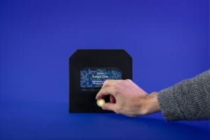
The two projects I researched in the initial stages of the group research project include Future Agency’s “Scout,” and solar energy chargers. Scout, as detailed on Creative Applications Network, is a “smart-home counterspy agent” that takes the responsibility of “intercepting data and visualizing it on its own display.” The data comes from the user’s usage of other interactive devices, including objects, websites, and devices such as thermostats, bulbs, TVs and Netflix and much more. In a world where the presence of technology continues to strengthen in all aspects of life, it may be difficult to keep track of all the information that is being shared across our devices. Scout will be able to keep an eye on this information on behalf of its consumers, for it acts as the router where all devices are to be connected to. As Scout receives information from our devices, it presents the data to our eyes, which ultimately, allows us to become more aware of our consumerism and the whereabouts our information is being shared to. The relationship between the user and the mechanism is ultimately labeled as a form of interaction. It indicates the presence of reciprocal action as both the consumer’s and device’s actions, are influenced by one another’s activity, creating a cycle of interaction. Ultimately, this, much-needed technology would be a perfect example that conforms to my standards of interactivity.

]

Creative Applications Net – Scout

http://s3-ap-southeast-1.amazonaws.com/ima-wp/wp-content/uploads/sites/3/2017/08/05164121/The-Art-of-Interactive-Design-brief.pdf

Researching Projects of Interactivity (Part II)

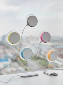
On the other hand, a project that I believe would not fit well with my definition of interactivity would be that of a solar energy powered charger (power bank). The invention would require the user to attach the charger to a surface and or wall that is exposed to natural sunlight, preferably a glass window. The charger would then process the energy gathered from the sun and transform that energy into electric power that is capable of charging one’s devices. Though this device would indeed include the constant interaction between the sun and itself, there is a minimal association between the technology and its beneficiary, the user. The user only needs to position the charger once for it to begin working, he or she is not required to provide the charger with constant input. This reality fails to conform to my original description of interaction, for the actors involved in the interaction fail to engage in a constant cycle of input and output.

Creating Our Own Project

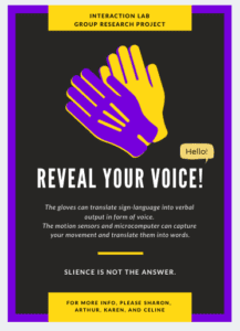
Taking into consideration all of our personal opinions of interactivity and suggestions for the group project, our group of five got together to decide on a finalized idea. We brainstormed what life would be like a hundred years from now and discussed some issues that could possibly still be researched in the future. We narrowed our main topics down to disability, environment and obesity. I continued to brainstorm about disabilities and the complications they bring to its victims, which is when I thought about the mute community. I began to wonder about the cruel reality where most individuals, including myself, take their voices for granted. Most of us are able to communicate with one another with our voices, but not all humans are granted with this privilege. This is where I came up with an idea to provide the mute community with their rightfully deserved voice, a gift my group would provide through sign-language interpretation gloves. I took into consideration how, even though they possess a language of their own, (sign-language) it is not a language that all humans learn. Through these interpretation and translation gloves, the mute community will finally be able to communicate freely with their fellow citizens, concurrently increasing the amount of interactions they encounter on a daily basis.  

We knew that there had to be a strong force of interaction between the actors, one that would allow for input and output to run in a cycle, constantly complimenting each other. The technology, would, in its final form, be capable of translating sign-language into audible voices. The futuristic invention would allow the mute community to reveal their hidden voices to the world and interact with the citizens around them, simultaneously boosting their confidence. While wearing the gloves, the user would perform a sentence or phrase through sign-language and find comfort knowing that their thoughts and opinions are finally being released into the world. The direct engagement of the user’s hand motions place an input into the gloves, allowing the advanced technology to process the information that has been provided. The gloves would then, through an attached speaker and or through a fully automated mobile app, emit an output that translates the user’s hand motions into spoken words. Ultimately, the user’s constant input is required for the gloves to process and produce verbal output.

We created these gloves, alongside an emotional presentation to truly describe just how technology is capable of changing the world as well as the lives of its habitants for the better. The gloves fit into my understanding and definition of interaction, for there are two actors present whom coincidently work cooperatively to achieve an ultimate goal. We hope that, in the future, our project will be able to help and possibly inspire all individuals on earth, even if it’s just by a small margin.

Recitation 3: Sensors, Celine Yu

Date of Recitation:  March 1, 2019

Documented On: March 3, 2019 

Partner: Megan Rhoades 

Reflection:

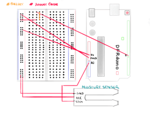
Megan and I selected the moisture sensor as the main component for the week’s Arduino exercise and decided that we would drive an output through a buzzer. We referenced other Arduino exercises from previous recitations in order to recollect our memories of the board’s set up. To ensure that the circuit was kept both clean and organized, Megan and I only used 3 different colored jumper cables: black, red and blue. The red was used to symbolize power whereas the black signified ground. Together with the blue, we used all 3 colored sets to interconnect the Arduino board with the breadboard for the buzzer to work effortlessly. 

Circuit 1: Buzz Output

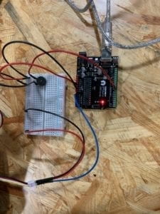
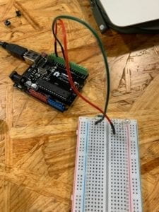
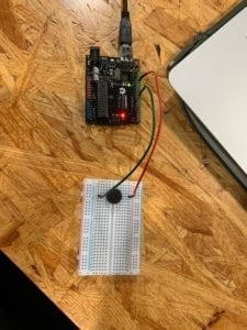
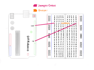
First, we attached a black wire to both the breadboard and Arduino board’s ground (GND) and proceeded to connect the Arduino’s 5V pin to the breadboard with a red cable. Next, we attached the buzzer to the breadboard through slots F26 and F29 and used one of the black wires to connect the buzzer’s anode side to the breadboard’s ground.  The cathode, on the other hand, was connected to the Arduino board’s digital PWM through pin #8 with a different red cable. The last step needed to complete the circuit was the inclusion of the moisture sensor, the component responsible for perceiving the circuit’s input. Megan and I recalled previous lectures and remembered how the yellow pin/wire needed to be connected to an Arduino board’s Analog pin. To complete this step, I took one of the blue cables and attached the moisture sensor’s yellow pin to the Arduino board’s A0 slot. 

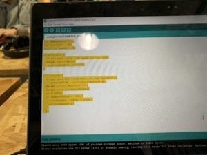
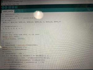
Immediately after finishing up with the circuit, Megan and I gave our undivided attention to the code. We first set integers of sensorValue = 0, and sensorPin = A0, values that corresponded to the moisture sensor’s analog pin, as described in the previous paragraph. Next, we typed in the constant integer, buzzer = 8, in order to relate the line of code to the circuit’s digital PWM. The void setup () section was completed with usual components such as: Serial.begin (9600) and pinMode, which we had set to ‘buzzer, OUTPUT.’ Afterward followed the void loop () section of the code, which was also one of the most confusing parts of the entire assignment. We set the conditions for when sensorValue > 300, the buzzer would emit a faint sound, similar to the output of previous recitation exercises.

Believing we had everything ready to go, we selected the accurate ports and uploaded the code to the Arduino circuit. Since we required a source of water for the moisture sensor, we decided to use the excess water from my water bottle to form moisture on our fingers. I placed my index finger onto the moisture sensor after wetting it and waited for the buzzer to sound. The output, unfortunately, did not occur. We were convinced that the failure was due to the lack of moisture on my finger, in which we decided to alter the code from sensorValue > 300 to sensorValue > 150. Once again, we repeated the trial but was still unable to get the circuit working properly. This is where the buzzer caught the attention of my eyes, I suggested to Megan that the buzzer was actually the source of the problem. Megan agreed with me, thinking that the buzzer could have been positioned incorrectly in terms of its power and ground complex. Together, Megan and I chose to change the direction of the buzzer so that the anode was attached to the ground and the cathode, connected to the Arduino board (Digital PWM). We were ecstatic to learn that the circuit finally began working, as the buzzer emitted a short ‘beep’ when my finger came in contact with the moisture sensor. We then discovered that there was still a significant amount of time left before class ended. To make use of our remaining time, Megan and I decided that we would challenge ourselves with a more advanced circuit, one that made more use of our coding skills. Without changing the formatting of either the breadboard or Arduino board, we went straight to work on Megan’s laptop. 

Together, we decided that we wanted to change the output of the circuit from a simple buzz to a random melody. This idea was sparked by last week’s recitation where I also used the buzzer as an immediate output. Megan and I searched for the toneMelody example under 0.2 Digital and copied and pasted the code into our own. We positioned integers Melody and noteDurations to the very top so that they functioned in the same region as the original 3 (sensorValue, sensorPin, buzzer). Next, we positioned the remaining code into the void loop () section by implementing it within ‘if’ and ‘for’ conditions. Believing that we had everything set and ready to go, we uploaded the code to Arduino and awaited our results.

Unfortunately, our first attempt did not go smoothly. Not only the did the buzzer fail to play a melody, but it also lost its ability to release a single output. Megan and I returned to the code to look for what may have gone wrong. We noticed a discrepancy between the example code and our own and immediately went on to fix it. We had accidentally forgotten to implement the ‘#include pitches.h’ component in our code, a portion extremely crucial to the circuit for it provided the Arduino with the melody’s chords and notes. Without this extra code, it was a given that the circuit would not work. We quickly added the pitches.h page, copied and pasted the defined notes from the 0.2 Digital example and proceeded to link the additional page to our main code. Following this, we made the decision to continue looking over our code to search for any other mistakes that could have occurred. This double checking turned out to be a good idea because we had discovered that constant #8 was in need of fixing. We changed the code by replacing the #8 with the constant integer we had provided it in the beginning (buzzer) and once again, uploaded the code to the circuit.

https://bpb-us-e1.wpmucdn.com/wp.nyu.edu/dist/0/13761/files/2019/03/IMG_3478-1.mov

This time around, the circuit finally worked, and just in time as well. We took turns moistening our hands with water and playing with the moisture sensor as we listened to the melody that played from the buzzer. With the remaining time in class, Megan and I decided that we would go over the challenges from our exercise in order to coordinate our documentation reports. Concludingly, we began working on the mandatory schematics sketch for the assignment on my iPad and made sure to make it as clear as possible for all audiences.

Question 1: What did you intend to assemble in the recitation exercise? If your sensor/actuator combination were to be used for pragmatic purposes, who would use it, why would they use it, and how could it be used?

Answer 1:  In this recitation, Megan and I were immediately enticed by the moisture sensor and decided that we wanted to build a circuit that would emit a notification or sound once it encountered a certain amount of moisture. A pragmatic example in which our circuit could be used is in relation to plants. For consumers who enjoy taking care of plants at home, work, or any environment, our sensor/actuator combination could be implemented beneath the plant and soil to detect moisture. Once the moisture sensor detects that the value of moisture has reached a certain minimum, it would set off the buzzer. The buzzer would then alert the consumer with either a sound effect or melody that plays on loop until the sensors detect that the value of moisture is above the minimum that is set, an output that would remind the consumer to water their plants. 

Question 2:  Code is often compared to following a recipe or tutorial. Why do you think that is?

Answer 2: I believe that when an individual is attempting anything new, they always need assistance from those who are more experienced than them. This theory can be applied to various hobbies, tasks, and careers such as cooking, makeup, constructing, etc. The need for an ‘instruction manual’ is attributed to the human’s need for knowledge and understanding of a situation and or task beforehand. Most people prefer to understand specific details about a certain task as compared to performing it blindly with no knowledge of the correct format and or methods. Most individuals, including me, require instructions and recipes to guide them through these tasks until they are somewhat comfortable with the information they’ve acquired and are confident that they can perform the task without assistance. Even when one has mastered a skill or task, there will always be room for improvement and learning. This tendency is an inherent factor that all humans share and includes the task of coding.

Question 3: In Language of New Media, Manovich describes the influence of computers on new media. In what ways do you believe the computer influences our human behaviors.

Answer 3: Throughout its existence, technology has impacted humans and their behavior in various ways, the most influential of them all include our computers and laptops, a form of mobile machinery we can take with us everywhere we go. To the millennial age, computers and phones are a necessity, items that cannot be forgotten about. There are apps and websites on the internet that users can access through their computers to educate themselves about various topics, most specifically, academic subjects. Though users have indeed enhanced and developed their cognitive thinking with the wonders of both the internet and computers/laptops, this technology also has great influences upon our human behaviors, some more negative than others. In recent years, society has witnessed the indomitable rise that is social media. As users are captured by social media and other significant apps, their eyes are fixated to their screens, a reality that ultimately affects the human being’s social skills and emotional behavior. A majority of consumers are hiding behind their screens, creating facades out of their friends and themselves, all while being unable to interact with others in real life. Though the computer (technology, internet) has evolved the world by assisting millions and millions of users, there will always be aspects of its technology that have negative effects on humans, human behavior is just a single example.

Recitation 2: Arduino Basics by Celine Yu

Date Of Recitation: February 22,  2019 

Documented on: February 25, 2019

Partner: Citlaly Weed

Reflection: Recitation 2 focuses on familiarizing oneself with the Arduino software and hardware through a total of 4 attempts at different circuits. For all circuits, I worked with my partner, Citlaly, who I had a great time creating circuits with. For continuity and time-efficient reasons, we decided that we would use Citlaly’s laptop for all coding and Arduino exercises. Since the both of us had already acquired an amount of knowledge from the first recitation and listened closely during the week’s lectures, the diagrams for circuits 1, 2 and 3 were all quite straightforward. We completed all 3 required circuits, and made significant attempts at circuit number 4 but was ultimately unable to complete it due to time constraints. Citlaly and I had chosen not to replace the switches with arcade buttons from the first recitation in order to leave more time for circuit 4, which was proven to be quite difficult.

Circuit 1: Fade

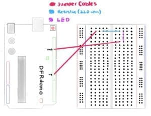
The purpose of the first circuit was to have a LED fade both in and out with the Arduino software and physical board. Citlaly and I grabbed two jumper cables, a 220-ohm resistor, and a LED to accompany the Arduino board and breadboard. We followed the clear diagram provided on the recitation website and got straight to work. The first step was to place the 220 ohm resistor onto the breadboard and into row 2 of columns D and G, knowing that the breadboard’s connection is divided into left and right. We then used a green jumper cable to connect one end of the resistor to the power on the Arduino board. Afterward, it was time to plant the LED. We made sure that the anode connected with the resistor and ultimately to the power supply by placing it in row 2 of the breadboard. Lastly, Citlaly and I attached the cathode end of the LED to a red jumper cable in row 5, which we would then connect to the Arduino board’s ground. We connected the circuit to Citlaly’s laptop through the Arduino board and continued to follow the instructions provided. We opened the Arduino software, went to file and found the Fading example under 0.3 Analog. Citlaly uploaded the code, but we were met with our first failed attempt. The LED did not light up, nor fade in and out as it was supposed to perform. This is when I remembered a tip our professor, Mr. Young had informed us about in class. I went to tools and looked down to find the Board and Port categories, and selected the appropriate port for the Arduino software. After completing the selection, we tried to upload the code once again, and to our surprise, the circuit worked this time around.

Circuit 2: toneMelody

The output that Citlaly and I strived to achieve for circuit 2 was for a speaker to emit a specific melody produced within Arduino. We made sure to disconnect the circuit from the laptop and remove both the resistor and LED from the breadboard as they were no longer needed. Citlaly and I placed a speaker or buzzer near the middle of the breadboard, ensuring that its pins were connected to separate sides of the circuit board. Following this, we connected the red and green jumper cables to each side of the buzzer and connected the Arduino board with the laptop once again. Citlaly and I were confident that we hadn’t made any mistakes and continued to open a new Arduino page with the toneMelody example found under 0.2 Digital. Unfortunately, we were unable to have the circuit working on our first attempt. Since we were confused as to what went wrong during the seemingly simple circuit, we asked for help from the teachers and assistants present during recitation. We soon learned that we had misplaced the red and green jumper cables that connected to both ground and power on the Arduino board to the incorrect sides of the buzzer. Our initial belief was that the position in which the components were connected did not matter, as long as they were attached, the circuit would work. This was ultimately, incorrect. We turned the buzzer around so that the anode side would connect to green power cable, while the anode would attach to the red ground cable. With our second attempt, we were able to successfully make the buzzer release a small melody, essentially completing the second circuit.

Circuit 3: Speed Game

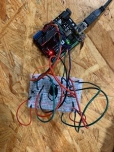
The third circuit was by far the most interesting circuit as well as the most difficult one to follow in terms of its foundation for it implemented a sense of interactivity for both Citlaly and I. We placed all major components down such as the buzzer, the switches, the LEDs, and the resistors in their positions on the breadboard and continued to interconnect all the pieces with an assortment of jumper cables that ranged from short to long and long to short. With the jumper cables, we also connected the breadboard to the Arduino base by utilizing slots, D11, D10, D8, D3, D2 as well as GND and 5V. When it reached this part of the circuit, things began to grow confusing as the number of components on the breadboard increased with each step. The circuit, unfortunately, did not prove to be a success as the LEDs failed to show any response to the manipulation of either switch. We then decided to utilize the multimeter to test the resistors, as we were aware that any single mistake would be crucial to the circuit. The multimeter discovered that one of the resistors presumed to be of 220 ohm was in fact a 10k ohm resistor. We immediately, switched the 10K ohm resistor with a new 220 ohm one and replaced it on the breadboard. We did a double take of the entire breadboard and made another attempt to get the speed game working. With the port and board categories accurately chosen, the Arduino board connected to the laptop and all components seemingly fitted into their rightful positions, we uploaded the Arduino code once again. Both of us then pressed the switches repeatedly and vigorously in an attempt to have our LED turn on first, which ultimately resulted in Citlaly’s victory. Circuit 3 was confusing at first, but after we traced our steps and focused our attention on each and every component, we were able to spot the mistake almost immediately, which allowed us to complete the third exercise with ease.

Circuit 4: Four-Player Speed Game

For this optional circuit, Citlaly and I partnered up with two other classmates from our recitation. We began to discuss the solutions that could help us transition our two-player game into that of a four-player one. We decided to list down the number of our switches, and the colour of the jumper cable that would connect to each slot in the Arduino board and breadboard. We noted the number of the slots we used as well in order to implement them into our code in the future. We soon hit a rough patch while trying to interconnect both breadboards with a single Arduino base. Unfortunately, due to time constraints, our group was unable to complete the fourth circuit despite our great efforts and attitude.

Questions and Answers:

Question 1: Reflect how you use technology in your daily life and on the circuits you just built. Use the text Physical Computing and your own observations to define interaction.

Answer 1:  Technology is found everywhere and is now inevitable when it comes to performing certain tasks on a daily basis. I use the microwave for breakfast, my laptop to complete assignments, and my smartphone to read the latest news. Technology has changed the way individuals communicate, play, work, study, learn and behave around one another. With its ever growing area for improvement and creation, technology is most of the times, created to improve all lifestyles. When this technology is partnered with physical computing, the possibilities are endless. As stated in the “Introduction to Physical Computing”, the very definition of physical computing entails the “creation of a conversation between the physical world and the virtual world of the computer”, which ultimately creates an interaction between the two worlds. According to the reading, two subjects require input, output and processing for an ‘interaction’ to occur between them,. They react with one another through a cause and effect complex that allows an output to be produced at the conclusion of the interaction. The circuits created in recitation 2 are perfect examples of physical technology combined with the wonders of physical computing. The correct wiring of components of the breadboard and the proper coding upon the Arduino software allows the circuits to produce results (output) such as: playing music, turning on/off lights as well as creating games (for leisure). The interaction between the physical world and its counterpart, the virtual world create technology designed for all audiences, and will continue to create for years to come.

Question 2: If you have 100,00 LEDs of any brightness and colour at your disposal, what would you make and where would you put it?

Answer 2: If I were given 100,00 LEDs of any brightness and any colour at my disposal, I would perhaps, If I had the knowledge and capability to do so, create an art piece that would have all 100,000 LEDs positioned so close together that from a distance they would appear to create a flat surface of lights. I would then create a program that allows the user to draw a simple image, or write a note that would eventually project onto the 100,000 LEDs as if it were being projected onto a TV or a screen. Each LED would change into a colour in respects to the design and or message the user has created on the program. Ultimately, it would enlarge the design and bring the piece to life by allowing it to shine through the lights of 100,000 LEDs. This idea would of course, require a lot of knowledge in regards to both computer programming and light engineering, but would ultimately be an amazing project if it were to be created in real life.