INTM-SHU 101 (006) – Week 4: Drawing Machines – Caren Yim

Purpose:  The purpose of this lab was to build a circuit incorporating the stepper motor and from there collaborating with a partner to use the circuits we built individually and create a drawing machine.


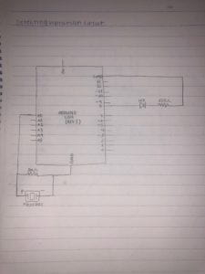
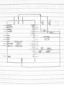
Part 1: Build the Circuit 

Components:
1*42STH33-0404AC Stepper Motor
1* SN754410NE IC Chip
1*Power Jack
112 VDC Power Supply
1* Arduino Kit

Circuit
Circuit

Process:  The process of building this part was easy given that we were provided the schematic and the code. Although it was a little hard to piece together the connections at first because the schematic had a lot of wires I was able to figure it out.


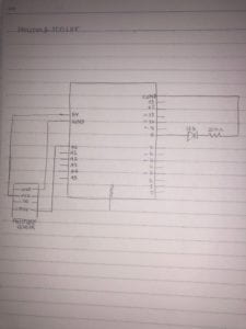
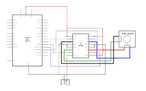
Part 2: Control rotation with a potentiometer

Components: 
The built circuit from Part 1
1*Potentiometer

Code
“MotorKnob” altered code

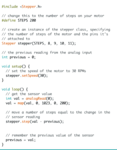
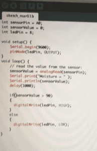
Process: In this step, we had to add a potentiometer to the circuit. To do this I connected the potentiometer to an analog pin and the other two pins to ground and power. I then ran then downloaded the existing code “MotorKnob” into the Arduino, but the rotation of the potentiometer the motor rotation was not matching. With the help of an instructor, I was told it was because I did not change the code to include map(). I needed to add the map() so that the values could be remapped to a different range. After, changing the code, the motor and potentiometer started working.  


Part 3: Build a Drawing Machine!
1*Partner built circuit
2* Laser-cut short arms
2* Laser-cut long arms
1* Laser-cut motor holder
2* 3D printed motor coupling
5*Paper Fasteners
1*Marker
Paper

Process: In this section, we had to pair up with a partner and combine our devices in order to create a drawing machine. We had a little trouble initially because our devices were not in sync and the motor was not staying in place and kept buzzing. My partner also did not change her code from part 2. When we fixed the problems, we finally got the drawing machine to work.


Reflection:

To me, circuit building and understanding wire connections is not the difficult part. I find that coding is the most difficult part. For me, It is hard to understand which each component in the code is supposed to do and how they work with each other. I think I need to familiarize myself more with the foundations of Arduino coding. In part 2 of this project, having to alter the “MotorKnob” code was confusing at first but after having it explained to me I believe I now have a stronger understanding of the map() function.

Overall, I found myself to really enjoy this project. It was nice to see all the concepts we have spoken about in previous classes being brought together. I especially liked how art and technology was brought together in this project.


Question 1

What kind of machines would you be interested in building?Add a reflection about the use of actuators, the digital manipulation of art, and the creative process to your blog post.

Inspired by this recitations project, I believe it would be interesting to build machines that don’t necessarily complete a given task but instead the machine itself produces art. Perhaps a machine that can paint actual landscapes. In the earliest of times machines aided in people to complete tasks now they are completing the task. That being said, I think it would be really interesting to see if we will get to a point in society where art is created only by machines.

Actuators takes a given energy source and converts it into motion. This process gives actuators the ability and variety to complete a lot of different tasks making it especially important in the realm of technology. With its ability to complete a wide range of tasks, it also has the freedom to create and aid in different projects, beyond technology. Today, we are already seeing the digital manipulation of art for example augmented reality which includes manipulating art with technology. Artists are using augmented reality in their works. Performers have already had lives shows using augmented reality. I believe that the future of art and technology is going to become more immersive and popular.

Question 2:

Choose an art installation mentioned in the reading ART + Science NOW, Stephen Wilson (Kinetics chapter). Post your thoughts about it and make a comparison with the work you did during this recitation. How do you think that the artist selected those specific actuators for his project?

I found the London Fieldworks created by Bruce Gilchrist and Jo Joelson to be a really interesting art installation. This art piece caught my eye because not only is it aesthetically pleasing, but the meaning behind it. It isn’t just about looking at the art it’s about using your other human senses to aid in how you perceive the art. It is different from the work we created in this recitation because in this recitation our projects only focused on the things we can see. The art piece was the piece the machine was drawing. In this project it is a “multi-sensual” work of art, it encourages individuals to find meaning from the art beyond what they can see. This allows for a wider interpretation of the piece because by combining noise, touch, and sight; the  experience is abstract.

INTM-SHU 101 (006) – Group Research Project: ClosetPod – Caren Yim

I initially saw interaction as two entities responding to one another. However, after reading Zach Lieberman’s reading and researching projects that incorporated interaction I had developed a deeper understanding of interaction. I came to understand interaction as being at least two actors expressing variable outputs that engage with one another and those outputs are interdependent on each other. There should be a level of exchanging in the process of interaction.

The two projects that I researched was “Alias” and the “EM Table”. The Alias is a teachable “parasite” that attaches to a smart assistant and the EM Table is a table that is able to light up fluorescent tubes within a short distance. To me, the Alias aligns with my definition of interaction because different levels of interaction are taking place. Through the app, the user is able to train the Alias to respond once a “wake-word or sound” is made. In response, the Alias turns on the home assistant when the sound is made. It also prevents the home assistant to from listening otherwise by interrupting its microphones. In all these interactions there is a response to the output. Every entity is working and responding to one another. However, the EM Table doesn’t quite align with my definition because, in the engagement between the table and the light the exchange is one-sided, they are not conversing with each other. Once the light is in the tables vicinity it turns on.

ClosetPod
ClosetPod Poster

In our project, ClosetPod, we first solidified a group definition of interaction. Interaction in itself is a broad term and we wanted to make sure our project would fulfill all our perspectives on what interaction entailed. After laying the foundation of our project we wanted our project to be able to solve a real-world problem. We were inspired by sustainability since we believe Climate Change will surely still remain an issue in 100 years.

ClosetPod
ClosetPod Device that holds the clothes
ClosetPod
Attachment to alter jacket sleeves according to weather
ClosetPod
Hood attachment for when it’s raining

We all are guilty of spending too much money on clothes so as a group we thought “What if we didn’t have to purchase seasonal clothes every year” this will help both the environment and allow us to save money. And that is where our idea blossomed. We came up with the idea to create a portable Closet in which an individual can easily carry around. The clothing within the ClosetPod are able to detect the weather and change according to the weather. In this project many entities are working together and responding to one another. The user interacts with the ClosetPod and chooses what they want to wear, the ClosetPod responds by making the article of clothing available. When the user puts on the article of clothing the clothing interacts with the weather and alters accordingly. All the parts of the project are responding and conversing with one another. The action occurring depends on the action of the previous entity.

INTM-SHU 101 (006) – Week 3: Sensors – Caren Yim

Introduction: The purpose of this lab was to get familiar with different types of sensors and to build circuits with the sensors. My partner and I worked with both the Vibration Sensor and the Moisture Sensor.


Vibration Sensor:
Components
1* Breadboard
1* Arduino uno microcontroller
1* Piezo Disc
1* mega ohm resistor
1* LED
1* 220 ohm resistor
Handful of Wires

Vibration Sensor Schematic

For this circuit, my partner and I used a Piezo Disc to detect vibration and in order to see if our circuit was working properly we attached a different output to our circuit besides the built in LED. To start, my partner and I first inserted the Piezo Disc into the breadboard then we took wires and connected the negative polarity of the disc to the ground and took another wire and connected the positive to A0. We then took the 1 mega ohm resistor and inserted one side connected to the same row as the positive polarity and the other side connected to ground. To connect the LED we used a 220 ohm resistor to reduce the current flow. We then ran the program with the Knock example on Arduino and it didnt work the first time. We realized that we didn’t have the polarity in the right way. After we determined our problem and fixed it the vibration sensor worked. We opened up the serial monitor to make sure the program was working as it should.


Moisture Sensor:
Components
1* Breadboard
1* Arduino uno microcontroller
1* Moisture Sensor
1* LED
1* 220 ohm resistor

Moisture Sensor Schematic

Code

In this circuit, my partner and I used a moisture sensor to detect moisture. We also included an LED so that we can verify if our circuit was working properly. We first inserted wires in to the moisture sensor. Then we connected the moisture sensors “GND”  into the microcontrollers ground, the moisture sensors “VCC” into the microcontrollers 5V, and the moisture sensors “SIG” into the microcontrollers Analog input 0. To attach the different output we used a LED and a 220 ohm resistor connecting to the LED. When we used the moisture in our hands to test out the moisture sensor the value in the serial monitor increased. In order to connect the moisture sensor with the LED we needed to add code to the original code that was provided to us. We first stored the LED pin into the code. The LED was connected to 8 so we typed in “int ledPin = 8;”. We then set the LED pinmode. Then we added an if else statement. This statement told the moisture sensor, if the value was above 90 to light up else if it is lower than 90 do not light up.


Question 1:

What did you intend to assemble in the recitation exercise? If your sensor/actuator combination were to be used for pragmatic purposes, who would use it, why would they use it, and how could it be used?

In the recitation exercise for the vibration sensor, we intended for the sensor to light up an LED when vibration was felt. If the vibration sensor were to be used for pragmatic purposes it can be used by establishments and homeowners who live near earthquake zones. Of course, the sensor would have to be altered so that it wouldn’t be as sensitive but it can notify people when an earthquake is about to come and allow them to find shelter. For the moisture sensor, we intended to create a device that can detect moisture and light up the LED when a certain amount of moisture is felt. This can be helpful for people who maintain the grass for golfing events. In the game of golf, the grass is very important. This device can be used to determine if the grass is too wet or if it is too dry. To use this device they can determine a standard and see if the grass fits the standards or not.

Question 2:

Code is often compared to following a recipe or tutorial.  Why do you think that is?

I think that code is compared to following a recipe or tutorial because you are giving a set of instructions for the device in this case, the microcontroller to follow. With code, you input a set of instructions and output is created as a response. The code provides step-by-step directions for the controller just like a recipe provides step-by-step instructions to the chef.

Question 3:

In Language of New Media, Manovich describes the influence of computers on new media. In what ways do you believe the computer influences our human behaviors?  

In today’s world, we have become heavily reliant on technology. The computer has simplified the way humans think and act. We have the ability to not do work and allow computers to take over us. This, in turn, has made humans heavily lazy therefore our overall knowledge has been reduced because there is no need to memorize everything. The computer has made everything accessible and allows us to communicate with people from long distances within less than a minute. Computers are becoming more and more automated, and the potential that computers hold is becoming more frightening.

INTM-SHU 101 (006) – Week 2: Arduino Basics – Caren Yim

Introduction: The purpose of this lab was to understand the basics of Arduino. This was done through the completion of four circuit projects.


Components:

1- Arduino Uno  
1- USB A to B Cable
1- Breadboard
1- Buzzer
2- LEDs
2- 220 ohm Resistors
2- 10k ohm Resistors
2- pushbuttons
Handful of Jumper cables


Circuit 1: Fade

Having been provided the schematic for this circuit we didn’t run into any problems. We were aware that the wires connected to the Arduino needed to match the programming for it. We also knew that we had to make sure the polarity of the LED was inserted correctly. Thus, when we ran the circuit, the LED was fading, we had successfully completed the task.


Circuit 2:  toneMelody

As with the first circuit, we were given the schematics, therefore, the task was not hard. We were able to successfully build the circuit and the speaker did emit the melody it was supposed to.


Circuit 3: Speed Game

 Circuit 3 schematic

This circuit was really challenging for my partner and I. We were not provided the schematic and instead had to follow the circuit diagram. This was a little challenging to read because of the abundance of wires in the diagram. At points during the progress of building it was hard to keep track of which wires were connected to one another. When we thought we had finished building the circuit we tried running it, but the Arduino was not turning on. The instructor came by to see what was happening and figured out that we had created a short circuit. And that was why it was not working the way we intended it to. We had connected too many wires and voltage was running through where it was not supposed to. The instructor helped us fix the problem and the game finally worked. In the future, I would be more cautious about where I am placing wires and read the diagram more carefully.


Circuit 4: Four Player Speed Game

For this circuit, we paired up with another group. As a group, we changed the wires so that the two breadboards were connected to one another. Afterward, an instructor came by and guided us in altering the code, we changed the brackets within the code and the four player game was working.


Questions

1. Technology in this day and age is inescapable. It is hard to even imagine a world without technology. Everything that we do is aided by the use of technology in some way shape or form. From completing an assignment to purchasing items, every day the use of technology is present. In the circuits that we built, it gave me a better understanding of the behind the scenes of the devices we interact with every day. Technology has been simplified towards its consumers causing us to not really realize the complexity of it and how different parts interact with one another behind the screen.

Building the circuits and running code through it gave me a better understanding of how there needs to be an input (code) that goes into the microcontroller and the microcontroller then processes the information and then outputs the instruction. As reflected in the text “Physical Computing” this process is what the root of interaction is; parts working together to complete a given task.

2.  If I had 100,000 LEDs of any brightness and color at my disposal I would make an art piece. I think using LEDs to create a portrait of someone would be pretty amazing. By programming specific LEDs to turn off and on at a given moment would allow the LEDs to take a different form. Using LEDs as a medium for art is also turning technology into an art form. I would want my work of art to be placed in a museum.

Caren Yim – Week 1 : Electronics and Soldering

Introduction: The purpose of this week’s lab was to understand the basics of circuits through the completion of three circuits and to learn how to solder.


Circuit 1: Doorbell

Components:

  • LM7805 Voltage Regulator: maintain a constant voltage level for the circuit
  • Breadboard: base that allows for circuit connections, usually used for prototyping stage 
  • Push button Switch: interrupts the flow of current going through the circuit which allows the speaker to turn off and on
  • Speaker: creates sound, in terms of the circuit it allowed us to know if our circuit was working
  • 100 nF Capacitor: stores electrical energy and allowed the LM7805 Voltage regulator to work
  • Wires: allow current to flow from one location to another
  • 12 Volt Power supply: supply power to the breadboard

Process: In Circuit 1, my partner and I had to familiarize ourselves with the symbols and their corresponding components. When we first started, we started by inserting the speaker on the breadboard and attempted to work around that. However, we were advised that to start, it would be best to insert the 12 volts and the ground first. This was helpful because it built our understanding of ground and volts. The first problem we encountered was when we placed the capacitor into the power bus and the ground bus. We were told that instead, we can attach it to the same row of the regulator since the rows were already connected to both the ground and 12 volts. In the end, we were successfully able to get the circuit working.


Circuit 2:  Lamp

Components:

  • LM7805 Voltage Regulator: maintain a constant voltage level for the circuit
  • Breadboard: base that allows for circuit connections
  • Push Button Switch: interrupts the flow of current going through the circuit which allows the speaker to turn off and on
  • LED: light emitting diode, emits light
  • 220-Ohm Resistor: prevent too much current from passing through to the LED, control current flow
  • Capacitor: stores electrical energy
  • Wires: allow current to flow from one location to another
  • 12 Volt Power supply: supply power to the breadboard

Process: The first step in this circuit was making sure the resistor was at 220 ohm, to do this we used a multimeter. Since half of the setup was identical to circuit 1’s setup, we only took out the parts that weren’t needed for the second circuit and worked from there. An error that was made in this process was not considering the polarity of the LED light. When we completed the schematic we were not sure why the LED wasn’t lighting up, we asked for guidance and were told it was because the polarity of the LED was inserted wrong. After fixing this, the LED light lit up when the switch was pressed. We were successful in creating circuit 2.


Circuit 3: Dimmable Lamp

Components:

  • LM7805 Voltage Regulator: maintain a constant voltage level for the circuit
  • Breadboard: base that allows for circuit connections
  • Push button Switch: interrupts the flow of current going through the circuit which allows the speaker to turn off and on
  • LED: light emitting diode, emits light
  • Resistor: prevent too much current from passing through to the LED, control current flow
  • Capacitor: stores electrical energy
  • Wires: allow current to flow from one location to another
  • 220-Ohm Resistor: prevent too much current from passing through to the LED, control current flow
  • 12 Volt Power supply: supply power to the breadboard
  • Variable Resistor: allows the current resistance to be adjusted

Process:  The materials needed for this circuit was almost identical to the second circuit except a variable resistor was added. This circuit was easy to build because only the variable resistor needed to be added. We were a little troubled at first due to not being able to figure out which part of the variable resistor corresponded with the ones in the diagram provided. However, we were able to figure it out and in the end, successfully completed the circuit.


Questions: 

1.  In the reading, the author defines interaction as “a cyclic process in which two actors alternately listen, think, and speak”. Based off of this definition the circuits that were built today showed a level of interactivity. This is because each component within each circuit in a sense was “listening” to the parts before them for instructions and then “thought” about its role and then by creating a reaction they “spoke”. This process is repeated once an individual gives the circuit the signal to start. Even the process of building circuits was interactive, we inputted the work and as a result, the circuits responded back to us by having the LED light up or even the speaker making a sound when the switch was pressed. These were all responses to an action and that is what interactivity is.

2. Interaction Design and Physical Computing can be used to create interactive art in many ways. An example of the lengths both these combined can do to contribute to the interactive art realm is a project inspired by Tony Quan, a paralyzed graffiti artist. By studying human behavior and combining that with computing it allowed for the production of interactive art. The eye-tracking art was able to move in conjunction with a part of the human body. Interactive art gives life to a new form of creativity and has endless possibilities.