INTM-SHU 101 (006) – Week 8: Serial Communication – Caren Yim

Exercise 1 : 

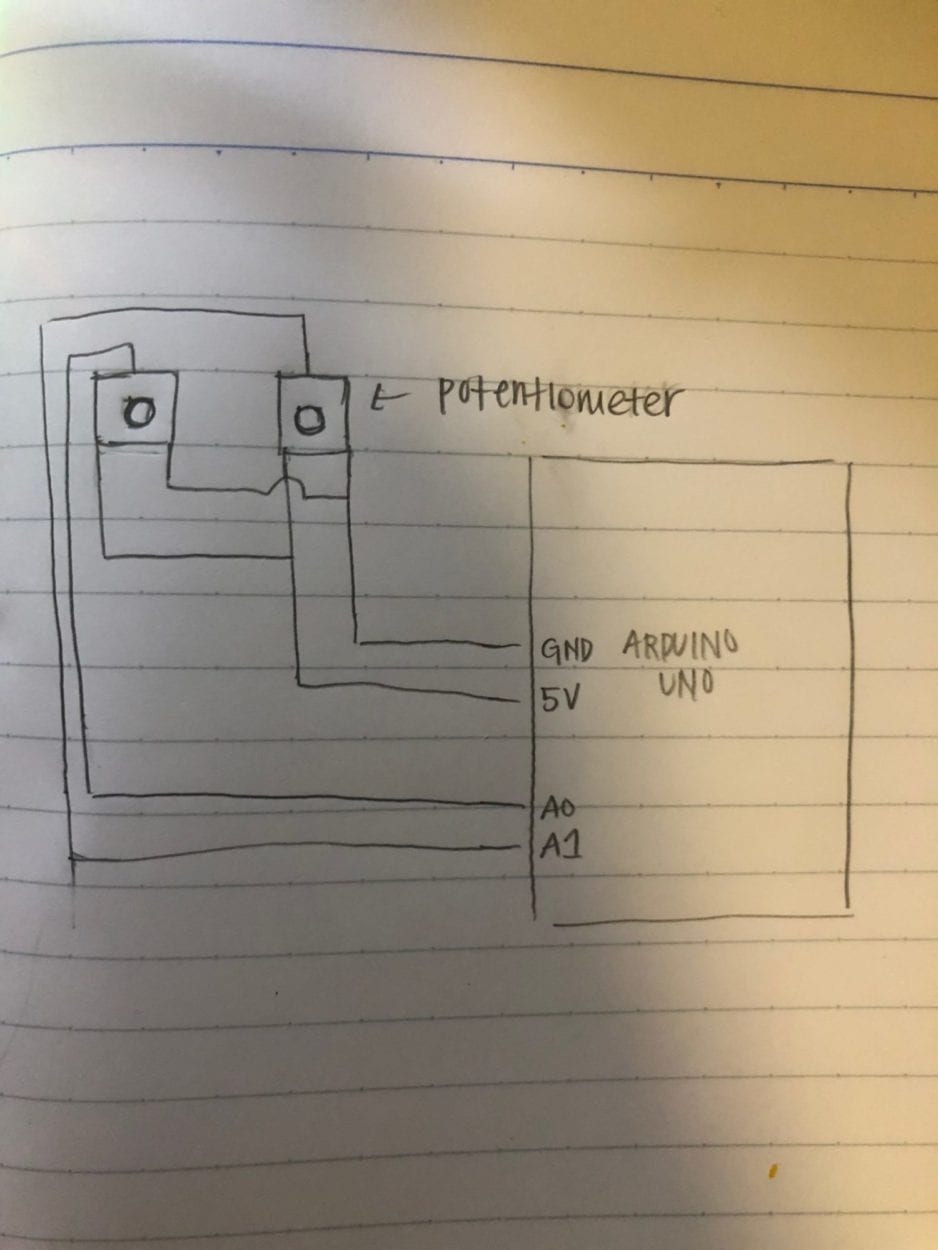
The intended goal of this assignment was to create an etch sketch by using Arduino to send two analog values to Processing through serial communication. When first looking at the given task, I was unable to understand how the Arduino and processing were sending information to each other. I was also confused as to where I should start. After the fellows explained the process of establishing the sensors in Arduino and then using the map(); function,  I understood the code and was able to get the project working. This project is representative of an interactive project because as I am interacting with the potentiometer by turning it,  the Arduino sends information to processing and processing visually displays the code. This occurs in a cyclic process until I am no longer interacting with the potentiometer. 

schematic

Arduino Code: 

void setup() {
Serial.begin(9600);
}

void loop() {
int sensor1 = analogRead(A0);
int sensor2 = analogRead(A1);

// keep this format
Serial.print(sensor1);
Serial.print(“,”); // put comma between sensor values
Serial.print(sensor2);
// Serial.print(“,”);
// Serial.print(sensor3);
Serial.println(); // add linefeed after sending the last sensor value

// too fast communication might cause some latency in Processing
// this delay resolves the issue.
delay(100);

}

Processing Code: 

import processing.serial.*;

String myString = null;
Serial myPort;

int NUM_OF_VALUES = 2; /** YOU MUST CHANGE THIS ACCORDING TO YOUR PROJECT **/
int[] sensorValues; /** this array stores values from Arduino **/
float x;
float y;

void setup() {
size(500, 500);
background(0);
setupSerial();
}

void draw() {
updateSerial();
printArray(sensorValues);

// use the values like this!
// sensorValues[0] x = map(sensorValues[0], 0, 1023, 0, width);
y = map(sensorValues[1], 0, 1023, 0, height);
fill(255);
noStroke();
ellipse( x, y, 20, 20);

// add your code

//
}

void setupSerial() {
printArray(Serial.list());
myPort = new Serial(this, Serial.list()[ 3 ], 9600);
// WARNING!
// You will definitely get an error here.
// Change the PORT_INDEX to 0 and try running it again.
// And then, check the list of the ports,
// find the port “/dev/cu.usbmodem—-” or “/dev/tty.usbmodem—-”
// and replace PORT_INDEX above with the index number of the port.

myPort.clear();
// Throw out the first reading,
// in case we started reading in the middle of a string from the sender.
myString = myPort.readStringUntil( 10 ); // 10 = ‘\n’ Linefeed in ASCII
myString = null;

sensorValues = new int[NUM_OF_VALUES];
}

void updateSerial() {
while (myPort.available() > 0) {
myString = myPort.readStringUntil( 10 ); // 10 = ‘\n’ Linefeed in ASCII
if (myString != null) {
String[] serialInArray = split(trim(myString), “,”);
if (serialInArray.length == NUM_OF_VALUES) {
for (int i=0; i<serialInArray.length; i++) {
sensorValues[i] = int(serialInArray[i]);
}
}
}
}
}

Exercise 2: 

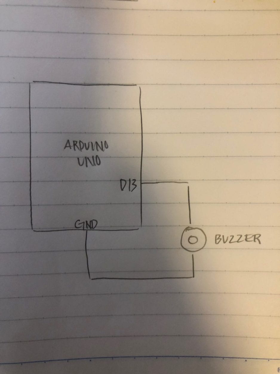
For this exercise our goal was to write a Processing code that sends values to the Arduino based on your mouse’s x and y positions interactions. Then we had to create a circut incorperating the buzzer. The arduino coded should read the serial values from Processing and translate them into frequency and duration for a tone, which will be displayed by the buzzer. Being given the hint to use the function tone() and the step by step instructions was very helpful.  This is represntative of interaction because through interacting with the mouse pad, it creates different sound frequencies based on the location of the mouseX and mouseY. 

schematic

Arduino Code: 

#define NUM_OF_VALUES 2 /** YOU MUST CHANGE THIS ACCORDING TO YOUR PROJECT **/

/** DO NOT REMOVE THESE **/
int tempValue = 0;
int valueIndex = 0;

/* This is the array of values storing the data from Processing. */
int values[NUM_OF_VALUES];

void setup() {
Serial.begin(9600);
pinMode(13, OUTPUT);
}

void loop() {
getSerialData();
tone(13, values[1], values[0]);

// add your code here
// use elements in the values array
// values[0] // values[1] }

//recieve serial data from Processing
void getSerialData() {
if (Serial.available()) {
char c = Serial.read();
//switch – case checks the value of the variable in the switch function
//in this case, the char c, then runs one of the cases that fit the value of the variable
//for more information, visit the reference page: https://www.arduino.cc/en/Reference/SwitchCase
switch (c) {
//if the char c from Processing is a number between 0 and 9
case ‘0’…’9′:
//save the value of char c to tempValue
//but simultaneously rearrange the existing values saved in tempValue
//for the digits received through char c to remain coherent
//if this does not make sense and would like to know more, send an email to me!
tempValue = tempValue * 10 + c – ‘0’;
break;
//if the char c from Processing is a comma
//indicating that the following values of char c is for the next element in the values array
case ‘,’:
values[valueIndex] = tempValue;
//reset tempValue value
tempValue = 0;
//increment valuesIndex by 1
valueIndex++;
break;
//if the char c from Processing is character ‘n’
//which signals that it is the end of data
case ‘n’:
//save the tempValue
//this will b the last element in the values array
values[valueIndex] = tempValue;
//reset tempValue and valueIndex values
//to clear out the values array for the next round of readings from Processing
tempValue = 0;
valueIndex = 0;
break;
//if the char c from Processing is character ‘e’
//it is signalling for the Arduino to send Processing the elements saved in the values array
//this case is triggered and processed by the echoSerialData function in the Processing sketch
case ‘e’: // to echo
for (int i = 0; i < NUM_OF_VALUES; i++) {
Serial.print(values[i]);
if (i < NUM_OF_VALUES – 1) {
Serial.print(‘,’);
}
else {
Serial.println();
}
}
break;
}
}
}

Processing Code: 

import processing.serial.*;

int NUM_OF_VALUES = 2; /** YOU MUST CHANGE THIS ACCORDING TO YOUR PROJECT **/

Serial myPort;
String myString;
int PORT_INDEX = 1;

// This is the array of values you might want to send to Arduino.
int values[] = new int[NUM_OF_VALUES];

void setup() {
size(500, 500);
background(0);

printArray(Serial.list());
myPort = new Serial(this, Serial.list()[ PORT_INDEX ], 9600);
// check the list of the ports,
// find the port “/dev/cu.usbmodem—-” or “/dev/tty.usbmodem—-”
// and replace PORT_INDEX above with the index of the port

myPort.clear();
// Throw out the first reading,
// in case we started reading in the middle of a string from the sender.
myString = myPort.readStringUntil( 10 ); // 10 = ‘\n’ Linefeed in ASCII
myString = null;
}

void draw() {
background(0);
if(mousePressed)
{
values[0] = mouseX;
values[1] = mouseY;
}

// changes the values
//for (int i=0; i<values.length; i++) {
// values[i] = i; /** Feel free to change this!! **/
//}

// sends the values to Arduino.
sendSerialData();

// This causess the communication to become slow and unstable.
// You might want to comment this out when everything is ready.
// The parameter 200 is the frequency of echoing.
// The higher this number, the slower the program will be
// but the higher this number, the more stable it will be.
echoSerialData(200);
}

void sendSerialData() {
String data = “”;
for (int i=0; i<values.length; i++) {
data += values[i];
//if i is less than the index number of the last element in the values array
if (i < values.length-1) {
data += “,”; // add splitter character “,” between each values element
}
//if it is the last element in the values array
else {
data += “n”; // add the end of data character “n”
}
}
//write to Arduino
myPort.write(data);
}

void echoSerialData(int frequency) {
//write character ‘e’ at the given frequency
//to request Arduino to send back the values array
if (frameCount % frequency == 0) myPort.write(‘e’);

String incomingBytes = “”;
while (myPort.available() > 0) {
//add on all the characters received from the Arduino to the incomingBytes string
incomingBytes += char(myPort.read());
}
//print what Arduino sent back to Processing
print( incomingBytes );
}

INTM-SHU 101 (006) – Preparatory Research and Analysis- Caren Yim

Through exploring the term interaction this semester, my perception of interaction has evolved. I initially saw interaction as two subjects conversing with one another. During the group project, however, I perceived interaction as being “at least two actors expressing variable outputs that engage with one another and those outputs are interdependent on each other”. Although I still perceive interaction to be that, I also now see that there can be different levels and quality of interaction. Through the completion of the midterm, the main addition I was able to add to my original definition is that in interaction,  the more parts there is for a user to interact with, the more complex the definition of interaction becomes. For instance from user testing, I was able to learn that if the piece considers its users’ different senses and creates different interactions based on the human senses, the level of interaction is elevated.

‘Ghost’ installation traps visitors in an interactive snow storm

Ghost Installation:  In this installation, this project lines up with my definition of interaction because there are many parts working together continuously in a cycle. The exhibition is created through the interaction that visitors have in the exhibit. Each visitor that enters the exhibit can see the remnants of its previous visitors. As the visitor interacts with the piece, the piece will output different variables from the intensity of the sound to altering the visuals. When no interaction is detected, the screen displays a landscape that features “the captured ghosts within” also known as its previous visitors. Each visitor has a different experience with the piece because not only are there many parts but also because they visually see different things. In addition, because the piece takes into consideration its users different senses and incorporates it into developing an interactive work, its level of interaction is elevated.

Vanishing Shades:  This project created by Lara Defayes does not line up with my definition of interaction because the exchange is too simple. The project is made up of six iPads layered on top of one another in a customized shelf. As the user touches the top iPad the color dissipates to the last iPad. The exchange between the user and the iPad is not complex enough. Although the pads changing color is dependent on the user, the user gains nothing from the iPad and there is no continual exchange between them. After a user pressed the top iPad, the rest of the other iPads are primarily dependant on one another to light up, the user is no longer needed. To me, interaction is essentially a conversation and in this project, the user and the iPad are not conversing with one another.

Interaction is a cyclic process that can be broken which incorporates at least two actors expressing variable outputs that engage with one another and those outputs are interdependent with each other. The key word in this definition is “engage”, an engagement is a conversation, it is not merely a situation of cause and effect, it goes beyond that. There are different levels of engagement, similarly to how there are different levels of interaction. The quality of interaction is dependant on many variables one of them is if the user’s different senses are incorporated within the work. Crawford agrees in his discussion of the importance in different levels of interactivity. He notes, “we might speak of interactivity as high, moderate, low, or even zero, thus solving our problem with the subjective nature of interactivity”(6). Anyone can argue that anything can be interactive, but the quality and level of interaction is a big part of what interaction essentially is.

INTM-SHU 101 (006) – Week 7: Processing Animation – Caren Yim

Recitation Exercise:

For the recitation exercise, our task was to incorporate animation into processing. I chose to alter my creation from recitation 6 to include interaction and animation we learned in class. At first, I only incorporated the “mousePressed” function so that the background would change into random colors when the mouse was pressed. I realized this was too simple of an interaction so I decided to animate my actual creation. I made my design rotate by utilizing the “ translate” and “rotate” function. In the beginning, I only utilized the “rotate” function, however, the design was rotating off the frame so I added the “translate” function so that it would rotate in frame, around the center. The last interaction I incorporated was when the mouse went inside the center circle, the tiny circles surrounding the center would change from white to black. To do this, I used an if statement and set a boundary in which if the mouse entered the ellipses would turn black to set the boundary I used “mouseX” and “mouseY”. Through the completion of this exercise, I was able to familiarize myself with using processing to animate and incorporated interaction. At first, I had trouble understanding what some functions are used for and this exercise really allowed me to gain a better understanding of the purpose of different functions and how they can be used.

CODE: 

void setup() {
size(750, 750);
}

void draw() {
stroke(255,255,255,250);
translate(width/2,height/2);
rotate(frameCount);

fill(255, 108, 15);
triangle(70,45,350,70,100, 500);

fill (54, 190, 255);
ellipse(150, 340, 150, 150);
scale(0.5);
ellipse(150, 340, 150, 150);

fill (104, 41, 255);
ellipse(150, 340, 100, 100);

fill(255, 89, 80);
ellipse(100, 250, 150, 150);
noFill();
ellipse(150,340,150,150);

fill(205, 255, 59);
ellipse(350, 200, 300, 300);
fill(250,28,224, 100);
rect(300, 240, 200, 200);

fill(247,22,30, 100);
rect(150, 200, 250, 200);
scale(0.5);
rect(150, 200, 250, 200);

fill(54, 59, 134);
triangle(100,400,400,600,500,450);

fill(250, 250, 250);
ellipse(350, 200, 50, 50);
fill(0, 0, 0);
ellipse(350, 200, 20, 20);

fill(0, 0, 0);
ellipse(150, 200, 50, 50);
fill(250, 250, 250);
ellipse(150, 200, 30, 30);

fill(0, 0, 0);
ellipse(300, 350, 175, 175);
fill(250, 250, 250);
ellipse(300, 350, 100, 100);
fill(0, 0, 0);
ellipse(320, 350, 40, 40);

if (mouseX> 275 && mouseX< 475 && mouseY> 275 && mouseY< 475) {

fill(10, 10, 10);
ellipse(150, 200, 50, 50);
}
}
void mousePressed() {
int r = int(random(0, 255));
int g = int(random(0, 255));
int b = int(random(0, 255));
background(r,g,b);
}

Recitation Homework: 

For this recitation homework I had the most  trouble with making the circle change colors as it was expanding and contracting. The first step was relatively easy, but when I got to the second and third step of this assignment I had trouble understanding which functions I needed to use. For the second step of changing the diameter and color of the circle I needed to declare variables and trying to understand what I wanted the computer to do was hard at first because I would mix up different variables. But after some trial and error I was able to get it working. By utilizing math equations for the second task I succeeded in accomplishing the task.  For incorporating the  “keyPressed ” function,  first I wrote and layed out what I wanted the computer to actually do and that helped with being able to translate it to code. Through the completion of this assignment I was able to realize how much coding and logic goes into creating a work that seems simple. In essence, one has to think like a computer in order to create a successful code. 

CODE:

int v = 2;
int dia = 300;
int changeColor = 1;
int i;
int x = 300;
int y = 300;

void setup(){
size (600, 600);
colorMode(HSB, 360, 100, 100);
}

void draw(){

background(359, 0, 99);
noFill();
stroke (i, 100, 100);
strokeWeight(20);
ellipse (x, y, dia, dia);

dia = dia + v;
if (dia < 100) {
v = 1;
dia = dia + v;
}
if (dia > 400){
v = -1;
dia = dia + v;
// this alters the diameter, allows the program to expand and contract
}

i = i + changeColor;

if (i > 100) {
changeColor = -1;
}

if (i < 0) {
changeColor = 1;

// this alters the color as it expands and contract
}

}

void keyPressed(){

if (key == CODED){
if (keyCode == UP){
y = y – 20;

}else if (keyCode == DOWN){
y = y + 20;

}else if (keyCode == LEFT){
x = x – 20;

}else if (keyCode == RIGHT){
x = x + 20;

}else {
x = 300;
y = 300;
}

// this limits the circle from going completely outside the screen
if(x >= 600) x = 600;
if(y >= 600) y = 600;
if(x <= 0) x = 0;
if(y <= 0) y = 0;
}
}

Midterm Documentation: “Quiet Box” – Caren Yim (Partner: Lana Henrich)

Context and Significance 

In our midterm project, Lana and I wanted to create a project that could be useful and serve a purpose. Taking what we had learned about the concept of interaction from the group project as our starting point, we were able to start brainstorming ideas for our midterm project. Having understood interaction as “being at least two actors expressing variable outputs that engage with one another and those outputs are interdependent on each other” we wanted to make sure our project had multiple actors interacting with one another. Initially, we wanted to create a lamp that turned on when someone clapped, but we realized it was too simple and a product like that already exists. Working from there, we ended up settling on creating a device that would detect a level of noise and react by turning red and start buzzing when the sound level gets too loud and remain green when the noise level is quiet. We envisioned our project to be in an area where it is normally quiet and should remain quiet; places like libraries and common areas. That way when the noise level gets too loud the device will turn red and make a sound. Our project is unique because it is something that is simple, yet can be very useful. It is of special value because it is a device that can be utilized in varying situations.

Conception and Design

3d printing

3d print

schematic
Project Schematic

In the process of designing our project, we knew that we wanted to make the design simplistic and easy to use for its users. In designing the box that enclosed our circuit, we kept in mind that we wanted the user to understand its purpose when using it. We knew we wanted to 3D print our box because we wanted the light to shine through the box. We also added a hole in the back of the box so that we could power the device without having the Arduino outside the box. A base was also 3D printed because we wanted to ensure that all the wires and breadboard would fit inside the box. Prior to making our box, we were advised to laser cut our box because 3D printing would take too long. However, we were adamant in 3D printing it because we knew that with the design of our device, 3D printing would yield the best results and was better suited for our project goals. The LED would not have looked as nice through wood or clear plastic from laser cutting. In the design of the box, we cut out the word “Quiet” so that users would know to be quiet. We didn’t feel a need to add any other words because we all associate the color green with being good and red with being bad. We intended the LED to in essence do the “talking” for us.

Fabrication and Production

code

code

code

In the production of our project, we ran into a lot of problems and as a result, our project went through a lot of changes. Initially, we wanted a gradient of colors for different meanings of noise level: green- good, yellow- a little too loud, red- too loud. We then realized adding yellow would be unnecessary for the goal of our device so we simplified it to only have red and green. We were also not sure as to where our source of light was going to come from. We started with individual LED lights and then decided a LED strip was better suited for us. The hardest part for us was coding. We were unsure as to how to code our program so that the LED light would turn red once a certain level of noise was detected. Throughout our coding process, we got a lot of guidance and help from teaching fellow, Leon. He helped us set our “if…then” statement and also how to make our program turn green when the level of noise is okay and turn red when the level of noise was too loud. We were advised in making our program reset itself every round. Making the program reset itself allowed us to successfully complete our project goal.

switch
Switch that was added after user testing
switch
Power source now located inside the design

During user testing, we got some suggestions in which we adopted into our final design. There were people who told us our project needed no altering. There were a few people who told us we should add a potentiometer so that the threshold of sound could be changed depending on the setting. We decided in the end not to follow through with that advice because we thought that since our device is meant for places where it is supposed to be quiet, by adding a potentiometer there would be no purpose. The advice that a lot of people told us to add which was included in our final project was adding a switch so that the power source would be included inside the device. That way the device would seem more compact and easier to use for the user.

Conclusion

The goal of our project was to create a device that would be useful in a setting like a college, where individuals value quiet spaces. We also wanted to ensure that the concept of interaction was incorporated into our project. In my perspective, our project fits my definition of an interactive project. There is consistent communication between the user and the device. Each actor gives a response to another actor and the process is cyclic. Once the audience understood our project, they were able to successfully interact with our project which went against my expectations. I expected users to understand what the device’s purpose was by simply looking at it, which wasn’t the case. Although our project was simple, our intended use for the device was achieved. I am now able to understand that in designing you have to focus a lot on user experience and the little details. In our case, an example is the sensitivity of the sound sensor. In the future, I would definitely consider how to better design our project so that it communicates better and efficiently with its user. I think also being open in taking advice from people and deciding what to carry over into the final is important. From our accomplishments, I am now able to understand the whole design process and the amount of time and effort it entails. 

INTM-SHU 101 (006) – Week 6: Processing Basics – Caren Yim

Kandinsky
https://www.guggenheim.org/artwork/1953

I chose Vasily Kandinsky’s Three Sounds because I was captivated by his use of simple shapes and the contrast in colors that was incorporated in the artwork. I also enjoyed the overlapping of shapes and the transparency of the shapes as they overlapped one another. The piece seems simplistic yet chaotic. 

code
Processing Code

In my process of creating a work inspired by Kandinsky’s Three Sounds, the hardest part was trying to place shapes in a specific area. Since the program works on a coordinate system I did a lot of trial and error. 

my piece
My Piece inspired by Kandinsky

In my piece created by Processing, I wanted to play with the idea of colors really being the forefront of the piece. Unlike, Kandinsky who used a dull background and chose certain shapes to be vibrant, I used primarily really neon colors. To contrast the neon colors I added circles filled in with black and white. Like Kandinsky’s piece, he too plays with the contrast of black and white in the far right corner. I think that although our pieces are not identical, being inspired by Kandinsky, I utilized a lot of his techniques. Kandinsky used a lot of overlapping in his piece, which I too attempted to incorporate in my processing project. Like him, I also utilized simple shapes like circles, triangles, and squares.

I believe that in some aspects Processing was a good means of realizing my design and in other ways, it wasn’t as good as a media. To start off, I think it wasn’t good because I felt a little bit constrained and limited as to what I could do. I was unable to add some of the textures and gradient of colors that Kandinsky had in his work. In my perspective, the emotions in a painting drawn by hand cannot be imitated in a work drawn on Processing.