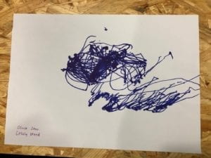
Recitation 6: Processing Basics – Citlaly Weed – Young

Colored Sticks

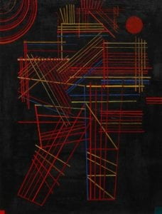
I chose this image by Vasily Kandinsky because I loved the black background contrast to the brightly colored lines, arches, and the single red circle in the corner. I have been recently into lines so I was really drawn to the picture.  My goal was to get a similar look, but I could not figure out how to make the lines colorful. My literal process was just putting as many lines and trying to cross them. I also did some arches and a circle in the corner to add something at a little more interesting to look out. Even though the color palette is simple I enjoyed the shade of the orange with a yellow undertone and how it goes with the gray lines. I am pretty proud of how it turned out like it to make it my screen saver on my laptop. Some obvious similarities are the single circle in a corner and the lines, but the lines are not as colorful.  Another difference is the layering of rectangle shapes. I believe processing was fun to mess around with but was difficult for realizing my design because I had to keep running it once I made little changes.  

Code:

size(640, 360);
background(0);

fill(204, 102, 0);
ellipse(30, 20, 100, 100);

fill(255, 204, 0);
line(30, 20, 85, 75);
line(30, 20, 55, 75);
line(30, 20, 205, 75);
line(30, 20, 105, 75);
line(30, 20, 5, 75);
line(30, 20, 355, 75);
line(30, 20, 205, 75);

color c = color(204, 102, 0); // Define color ‘c’
fill(c); // Use color variable ‘c’ as fill color
rect(175, 175, 105, 160); // Draw left rectangle

stroke(204, 102, 0);
rect(180, 180, 106, 161);

fill(255);
line(30, 20, 85, 75);
line(30, 20, 85, 20);
stroke(126);

line(150, 150, 385, 320);
stroke(126);

float blueValue = blue(c); // Get blue in ‘c’
println(blueValue); // Prints “220.0”
fill(0, 0, blueValue); // Use ‘blueValue’ in new fill
rect(200, 200, 106, 161); // Draw right rectangle

line(250, 150, 385, 320);
stroke(126);

line(350, 50, 385, 320);
stroke(126);

line(450, 5, 385, 320);
stroke(126);

line(5, 319, 285, 320);
stroke(126);

line(80, 119, 85, 320);
stroke(126);

line(160, 250, 185, 5);
stroke(126);

line(260, 250, 185, 5);
stroke(126);

line(260, 250, 360, 111);
stroke(126);

line(260, 60, 60, 160);
stroke(126);

arc(150, 155, 150, 150, 10, HALF_PI);
noFill();
arc(150, 155, 160, 160, HALF_PI, PI);
arc(150, 155, 170, 170, PI, PI+QUARTER_PI);
arc(150, 155, 180, 180, PI+QUARTER_PI, TWO_PI);

stroke(204, 102, 0);
arc(350, 350, 480, 480, 0, PI+QUARTER_PI, OPEN);

stroke(204, 102, 0);
arc(350, 50, 480, 480, 0, PI+QUARTER_PI, OPEN);

arc(250, 250, 580, 580, 0, PI+QUARTER_PI, PIE);

color b = color(204, 102, 0); // Define color ‘c’
fill(c); // Use color variable ‘c’ as fill color
rect(600, 75, 90, 560); // Draw left rectangle

fill(255, 204, 0);
line(630, 20, 85, 75);
line(630, 20, 355, 75);
line(630, 20, 205, 75);

arc(550, 55, 50, 50, 0, HALF_PI);
noFill();
arc(550, 55, 60, 60, HALF_PI, PI);
arc(550, 55, 70, 70, PI, PI+QUARTER_PI);
arc(550, 55, 80, 80, PI+QUARTER_PI, TWO_PI);

Picture: 

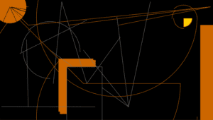
I think this looks dope.

Recitation 4: Drawing Machine! – Young – by Citlaly

The first task by myself:

Materials:

For Steps 1 and 2

1 * 42STH33-0404AC stepper motor needs more power than the Arduino provides (5v). -1 * power jack and 1 * 12 VDC power supply- the extra power the stepper motor needs to do its turning. 1 * SN754410NE ic chip which is the H-Bridge (the one that looks like a millipede) that can change the direction of rotation by not needing to change the circuit to change the rotation. 1 * Arduino kit and its contents (connecting wire jacks). 

BreadBoard:

I began with connecting all the little legs of the H-Bridge to the Arduino and to the motor. After I thought I connected everything in correctly I asked one of the helpers to check if I connected everything properly (I did not want to hurt my computer). Once they checked through they showed me that when it came to power and ground I could just connect the power and ground of the Arduino into the power and ground of the breadboard. That made connecting the 4 grounds much easier! I then added the potentiometer so I could make the motor twist and turn. Once I was good to go it was coding time.

Coding:

After copying and pasting 

/*
 * MotorKnob
 *
 * A stepper motor follows the turns of a potentiometer
 * (or other sensor) on analog input 0.
 *
 * http://www.arduino.cc/en/Reference/Stepper
 * This example code is in the public domain.
 */

#include <Stepper.h>

// change this to the number of steps on your motor
#define STEPS 100

// create an instance of the stepper class, specifying
// the number of steps of the motor and the pins it’s
// attached to
Stepper stepper(STEPS, 8, 9, 10, 11);

// the previous reading from the analog input
int previous = 0;

void setup() {
  // set the speed of the motor to 30 RPMs
  stepper.setSpeed(30);
}

void loop() {
  // get the sensor value
  int val = analogRead(0);

val = map(val, 0, 1023, 0, 200);

  // move a number of steps equal to the change in the
  // sensor reading
  stepper.step(val previous);

  // remember the previous value of the sensor
  previous = val;
}

I learned what a map function was I learned that it helped match the movement of the knob with the rotation of the motor because the motor is a 200 and the original was 1023 (very out of sync).  The bolded thing above is the map function. After that, it was time to find a partner so we could put our motors together and make a great piece of art (scribbles).

https://www.youtube.com/watch?v=6qDtbvoKVoQ

For Step 3

2 * Laser-cut short arms
2 * Laser-cut long arms
1* Laser-cut motor holder
2 * 3D printed motor coupling
5 * Paper Fasteners
1 * Pen that fits the laser-cut mechanisms
Paper

The assembling of the arms to hold the marker was pretty easy. when it came to putting in the paper fasteners to hold the arms together one had had to press the arms together (so they were not loose) while the other folded up the paper fasteners legs into place. Once they were put together my partner and I rotated our motors into a pattern that was scribbly, but we liked.

https://www.youtube.com/watch?v=anM7HbU1arg

Result!


Question One:

What kind of machines would you be interested in building? Add a reflection about the use of actuators, the digital manipulation of art, and the creative process to your blog post.

Answer One:

I have really been missing my microwave from home so the kind of machine I would want to make is a customizable microwave. I would add instead of a popcorn option I would choose a ramen option so that the microwave processor tells the actuator to stop heating leaving the perfect temperature for my ramen cup. Now, the ramen option started as an idea which after testing needs person testing. The feedback and the things I  can learn from people like if it is suggested that there be a 30-second button and or that the microwave when the time is done the door opens automatically. Then I can use this information and incorporate it into not only my personal microwave but into the microwave of other people. 

Question two:

Choose an art installation mentioned in the reading ART + Science NOW, Stephen Wilson (Kinetics chapter). Post your thoughts about it and make a comparison with the work you did during this recitation. How do you think that the artist selected those specific actuators for his project?

Answer two:

I found Ashok Sukumaran project interesting, “In Park View Hotel, the Indian artist Ashok Sukumaran invited viewers to use a special scope situated in a public park to view hotel windows across a street. If the window belonged to a room Sukumaran had chosen to be activated, a light would appear to move across the hotels façade, tracing a path down to the lights in the park” (108). It somehow makes the distance closed between the person and the particular window through the connection of lights. The obvious contrast is the scale that Sukumaran was able to use to make this connection, but there was a smaller scale connection made during the recitation. The connection was between my partner and I motors and the rhythm we developed to make what we did.  so no matter if it is a connection of a hotel room to a person in the park or two motors next to each other the connection is still there and makes an impact. I think maybe Sukumaran went about choosing lights as actuators because light, for me, has a big impact. It is contrasting to the dark and the overall feeling is positive when it comes to light. I want to assume the goal was to light the viewers from a lonely hotel room to a connection to a park of people.

Group Research Project: Individual Reflection- Young – by Citlaly Weed

 Interaction What is it?

Interaction has never been a word that I personally questioned the definition of or what it means when something is interactive.  Reading “The Art of Interactive Design” by Chris Crawford has inspired my definition of Interaction.  I agree that interaction should be seen as a conversation. Instead of there being just one possible output, interaction is varying inputs that can create varying outputs…the puppet show is still interactive only it is interactive on a different level. Crawford says that there are different levels that interaction can be which I agree with. 

A project that alines with my definition of interaction as:

At least two actors, an aninmal actor being one, engaging each other with many different inputs and outputs causing both being interdependent of each other.

The Cruise Control for Pedestrians is an interactive project where a small electrical stimulator on your leg suggests to the person using it a particular pace or route. The two actors would be the person and the electrical stimulator. The person’s pace and where they need to be are have varied input that the electrical stimulator picks up with this information the stimulator can suggest to you multiple types of paces and directions. This, although, there is no verbal communication between you and the electrical stimulator there is still a conversation about how fast or slow you are should be going and to move out of the was if there is something in your way.

A project that did not align with my definition was the EM table. The EM table is basically a table that lights up a fluorescent tube through its own localized electromagnetic field. This type of interaction does not align with my definition of interaction because there is no conversation. The fluorescent tube is placed by the table and the electromagnetic field lights it up that is it. There are not multiple possible inputs or outputs it is expected that when fluorescent lights are placed on or near the table they light up.  My understanding of the interaction between the light and the table is not strong enough to be able to define it as purely interactive. I must have decided that for something to be purely interactive there has to be a human or animal (plants/fungi too) as at least one of the two actors.

Our project was the ClosetPod where the two actors were you, the owner, and the ClosetPod. The design of the object was inspired by not only the AirPod but also sustainable fashion. The idea was that the clothes could change depending on if it was cold, rainy, or hot. Thus, the ClosetPod would be the only type of clothing needed. There are also options for designing or purchasing clothing style templates to be downloaded on the existing material. First off the customizable option allows there to be many inputs, but also the speed of weather change already, imagine 100 years from now, creates many variable inputs on the jacket. A shirt then being able to respond in many ways by either growing a hood or sleaves. Interaction is more than one action happens one and a result is the end. Interaction is the involvement engages a person mind with mediums such as technology.


Website used:

https://gizmodo.com/12-fascinating-projects-from-the-bleeding-edge-of-inter-1700656949

Recitation 3: Sensors – Young- by Citlaly

  Vibration Sensor

  • Breadboard to Arduino:
    • We used a piezo disk sensor that senses vibration and connected it to the power the Arduino and ground. then connecting the piezo disk sensor to a 1 mega-ohm resistor connecting that to the ground of the Arduino. We then connected a LED output 8 and a 220-ohm resistor into the output ground.  It did not work at first because we had the polarity reversed for the LED then we fixed it and it worked and when we hit the plate the light lit up.


https://youtu.be/oWiOaBwKTd0

  •      Code:
    • Arduino>File>Examples>0.6Sensors>Knock 

                 code from the Arduino website.

Moisture Sensor

  • Breadboard:
    • The sensor was slightly more difficult to make. First, we connected the moisture sensor first the ground to the ground of the Arduino, The Vcc (the red wire)  to the power of the Arduino, and lastly the yellow wire of the moisture sensor to A0 on the Arduino. We kept the light that we used for the circuit before. 
  •      Code:
    • The coding was also slightly tricky. Off of the website Seeedstudio we had initially copied and pasted the first example of coding :

int sensorPin = A0;

int sensorValue = 0;

void setup() {

Serial.begin(9600); }

void loop() { // read the value from the sensor:

sensorValue = analogRead(sensorPin);

Serial.print(“Moisture = “ );

Serial.println(sensorValue);

delay(1000);

}

          But when we were touching the moister sensor we notice the light was turning on and off; however, instead of showing the moisture level it was saying knock. It turned out that the coding from the last sensor was still lingering so we had to go into the coding and add the action of the light. 

int sensorPin = A0;

int sensorValue = 0; 

int ledPin = 8;

void setup() {

Serial.begin(9600); 

pinMode(ledPin, OUTPUT); 

}

void loop() {

// read the value from the sensor:

sensorValue = analogRead(sensorPin);

Serial.print(“Moisture = “ );

Serial.println(sensorValue);

delay(1000);

(sensorValue > 90)

{

digitalWrite(ledPin, HIGH);

}

else

{

digitalWrite(ledPin, LOW); 

}

       After adding the coding for the LED the instead of knocking the computer was reading the moisture.

https://youtu.be/08jdgCUSD5g

Question one:

What did you intend to assemble in the recitation exercise? If your sensor/actuator combination were to be used for pragmatic purposes, who would use it, why would they use it, and how could it be used?

Answer one:

I personally intended to find out what the vibration sensor did to see if it was the sensor I was looking for, for my video game idea. And it was? I asked questions and was told that if I were going to use one to use a more sensitive one and that if I were going to put it on the floor I should instead use some sort of board so the vibration could sense better the vibration caused by jumping or stomping. A vibration sensor realistically can be used to measure the vibrations of a machine to check whether the machine is healthy or not. Maybe a mechanic would use it on a car if an own noticed anything a little off. It might be used or already be programmed in the car and they somehow measure it and see if the vibrations are off from the usual and diagnose it an unhealthy car.

Question two: 

Code is often compared to following a recipe or tutorial.  Why do you think that is?

Answer two:

This is totally true. I think it more closely aligns with a baking recipe because with baking every ingredient must be mixed and measured to perfection.  Code is the same way because if you get a single missed letter, spelling. or capitalization wrong your cake is coming out wonky and the texture completely wrong. There is also the box cake mix of code where you copy and paste code too which you can not possibly mess up, but sometimes it does not come out right or you need to add something to make the code work for a particular situation ( like we did in the moisture one). 

Question three:

In Language of New Media, Manovich describes the influence of computers on new media. In what ways do you believe the computer influences our human behaviors?

Answer three:

It may be too soon to tell, but as gerneration Z becomes adults the changes in behavior may be more evident.  As a generation that grew up with computers and the internet the tendencies to think and generate ideas can be similar to a computer. From  Language of New Media Manovich explains periodic updates as the updating of new software. The rush of new updates and software that bombard us each day the need to be up to date can be an alteration to human behavior. The constant need to be connected to the newest thing or the new capability to create in even more detail to the average person (‘Photoshop, “Microsoft Word”) has changed human behavior to not only be apart of the next big thing but to also make it.

Recitation 2: Arduino by Citlaly

First Circuit

  • Breadboard to Arduino
    • First, we attached the resistor to D9 output on the Arduino. Then the LED to the resistor and from the LED connected that to the ground of the Arduino.
  • Code
    • On the Arduino software, we followed the directions of Arduino>File>Examples>03.Analog>Fading and successfully got the light to fade!

IMG_8278.TRIM

Second Circut

  • Beadboard to Arduino
    • We simply attached the speaker to D8 output on the Arduino and attached it to the ground of the Arduino.
  • Code
    • We followed the Code: Arduino>File>Examples>02.Digital>toneMelody; however, we were having an error message and it turned out we did not have the code set up with the right port of the Arduino. 

IMG_8279

Third Circuit

  • Breadboard to Arduino
    • On www.tinkercad.com we found the circuit. After connecting the ground and power of the breadboard to the ground and power to the Arduino, and also connecting the power and ground of both sides of the breadboard. My partner and I started from the outside in (each having our own side)of the circuit. First, we connected the button and connected that to power on the breadboard. Then we connected the button to the 10 resistor and connecting that resistor to ground on the breadboard. Then starting with the positive side of the  LED into #2 output on the Arduino and the negative to the 220 resistor, but it was wrong so we switched it connecting the negative side to the #2 output and the positive to the 220 resistor.  Then connecting the 220 resistor to ground on the breadboard we finally came to the end connecting the speaker in the middle while also connecting the positive side to #8 output on the Arduino and the negative side to ground on the breadboard.
  • Code
    • The code we simply copied from www.tinkercad.com and it ran after a check on all the wires connections.

IMG_8281

Fourth Circut 

Here we ran out of time, but we experimented attaching a second breadboard to another and have them share one Arduino. All we finished was the attaching since time was spent in trying to find long enough wires leaving us never finding out if our master pice worked.

Question One:

Reflect how you use technology in your daily life and on the circuits you just built. Use the text Physical Computing and your own observations to define interaction.

Answer One:

My daily life is consumed by technology because as it grows the more it is used to complete assignments and used for entertainment. Much of the input and output of any of my technology, laptop or phone, is done for me. All I do is either type or click and I trigger an already programmed processing. The circuit is different, this time I am the one putting together the output and eventually need to find the correct input for whatever I am trying to make. This interaction is more of a higher degree of interaction because of the hands-on work to create the output, not knowing whether the processing will be a success, rather than using an already made input and output knowing the processing will be a success.  There is more conversation that goes into making than using.

Question two:

If you have 100,000 LEDs of any brightness and color at your disposal, what would you make and where would you put it?

Answer two:

I would want to make a covered slide where it is dark on the outside, but once inside it is lit up by a rainbow of colors at a not too bright setting that it hurts the eyes (make the brightness adjustable). I would want to take this to the DuPont Hospital for Children that is local to me where I volunteered back in Pennsylvania. I would want to make it safe for kids with any disability to be able to use it, but most importantly something fun for the kids. There could be different themes too like underwater or rainforest and put audio in to make their situation transform.