Whack A Thumb – Connor S – Inmi

Conception and Design:

As I began considering my final project, the hardest part was deciding what theme or type of interaction it would be. From the beginning I was fairly set on creating a game of some kind that was usable by a wide range of audiences and did not involve an overly complex design in the hope not to confuse or alienate anyone from the experience of using whatever it would end up being. At first, my thoughts revolved around the idea of accessibility, and more specifically, providing a user experience that would be unquestioned in a sense because of how obvious the design is in terms of design, aesthetic, usability, etc. In following what I understood and appreciated about good design, I wanted to reintroduce and expand upon something that the majority of users would be familiar with, which is part of the reason why I went with a thumb war type game. Another reason I chose to use a thumb war as my inspiration is because a standard thumb war between two people literally fits in the palm of your hand, and I wanted my project to be as unintimidating and intuitive as possible. 

Fabrication and Production:

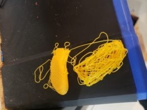
I knew my project would eventually be some sort of handheld device, but I wanted to be sure not to come up with an overly complex or ambitious design only to reach a roadblock because of the logistics of making it. I came to the conclusion that to make a functioning “thumb war”, I would need: (1) Some sort of handle to emulate the experience of holding a hand as one would in the event of a thumb war, and (2) a thumb that could move at a brisk enough pace to create a challenge. With this design concept in mind,  I started to consider the various tools at my disposal. I was lucky enough to find a piece of pipe in the fabrication room I could cut to use as a sturdy handle. I  wanted to create a simple to understand, yet challenging user experience, and concluded that an effective way to make this goal a reality would be to attach a thumb to a servo motor to mimic some of the challenge and quick thinking associated with pinning a real thumb. My first iteration included a flat, makeshift thumb made from cardboard, and while this worked for the purpose of movement and durability, multiple people suggested I 3D model a more realistic thumb to add to the experiential/immersive aspect of my project. Even though I ran into a bit of trouble with the printer at first…

…I would consider the decision to include a more realistically sized and shaped thumb a good one. 

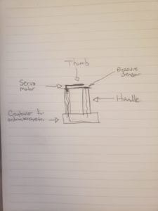
 Since this would be a game, I needed to incorporate something that could be used to indicate the user successfully pinned the thumb, which is how the employment of a pressure sensor came in to focus. The pressure sensor serves as an appropriately sized target to pin the opposing thumb, but a potential problem I encountered with this idea was the fact that someone could accidentally trigger the sensor without successfully pinning the thumb. For this reason, since nobody playing the game would ever hold their thumb flat on the surface for an extended time while the game is afoot, I decided to add a condition in my code that required the sensor be held for at least 3 seconds to trigger a victory. After completing a decent amount of the code and wiring for the project, I realized I would need somewhere to store the Arduino, breadboard, and all the wires, which is how I arrived at this rough sketch: 


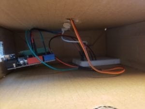
After my code was settled, the physical production process was relatively straightforward. I needed to feed wires through holes cut into the top of the bottom container and top surface, while also ensuring the project remained simple and clean in appearance. 

I thought this would be a good way to house all the necessary components, while not taking up an inordinate amount of space, or detracting from the design’s simplicity with uncovered wires. As shown in the photo above, there would have been a lot of visually unpleasing aspects of the project visible if not for the admittedly bulky, but necessary bottom container.         

Conclusions: 

The initial goal of my project was to create an interactive experience with an intuitive, simple design that would not alienate anyone due to its over-complexity, and I feel that with those criteria in mind, I successfully laid the groundwork for how a professionally produced thumb war game could operate and look. My definition of interaction was centered mainly on the concept of user friendliness in the form of prompts and responses provided by the design in question, and I think my project achieved these goals to varying extents. I think “Whack A Thumb” was user friendly in the sense that almost anyone could understand the concept, its uses, and the game play mechanics after a quick inspection.  While my biggest regret is that I spent too little time on ensuring the physical project would retain its structural integrity, I still have faith in my project’s concept and presentation. If I had more time I would make sure the device is made entirely from a durable yet light-weight material, and include a more ergonomically designed handle. 

Looking back on my process planning, constructing, and implementing my project, I learned that, while the basic concepts involving its design and function were well-formulated, there is no substitute for repeated and thorough user testing which help contribute to a fully polished final product. A seemingly foolproof concept will almost always encounter unexpected troubles when attempting to implement the idea in an uncontrolled environment. If I could add a footnote to the original definition of “interaction” I proposed in the beginning of the semester, I would stress the fact that the principles of interaction are observable between the user and the project, and not the user, project, and creator. Implementation matters a lot, and even if something “works” for the designer, it certainly will not to the same degree with the user.        
Recitation 8 – Connor S.

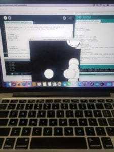
Once I understood/got a refresher from a fellow about the line of logical thinking behind creating an Etch A Sketch type experience with Arduino and Processing, I was able to feel miles more confident in my ability to grasp the methods used to facilitate serial communication between the two programs. After about 35 minutes of going over a step-by-step guide on connecting Arduino and Processing and how to implement certain functions and syntax that allow them to effectively communicate, I began working on the initial stages of an Etch A Sketch: 


Although it’s a little hard to make out from the photo’s atrociously bad quality, I began by following the instructions in the recitation site, and essentially made an Etch A Sketch of a bunch of trailing circles rather than one continuous line. After fiddling with the code for a little while, trying to determine the best way to form a line similar to that of an Etch A Sketch, I felt as though the line was perhaps the easiest component to produce, with delayed ellipses and setting up serial communication initially being the most difficult parts of the process.   


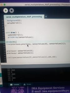
The image shown above demonstrates the relative simplicity of the code used for this recitation, a development that surprised me considering my slow start to getting my bearings with setting up serial communication. While I did not have time during the recitation to complete the make a musical instrument section, I did however come to understand the added benefit of knowing how to work with Arduino and Processing simultaneously.

Recitation 10 – Connor S.

I believe Young did a great job in his workshop on serial communication explaining how to send multiple values from Arduino to Processing. I learned that the process is fairly simple in that it requires fairly little on the Arduino side, and is relatively easy to grasp after taking some time to become acquainted with the format. 

The examples given explaining how to send information from Arduino to Processing and vice versa were helpful in understanding the relationship between the two programs and how they communicate with each other. I especially enjoyed learning more about sending multiple values from Arduino to Processing because I could see myself using this feature in future projects involving physical interactions.      

Arduino code from example:

// For sending multiple values from Arduino to Processing

void setup() {
Serial.begin(9600);
}

void loop() {
int sensor1 = analogRead(A0);
int sensor2 = analogRead(A1);
int sensor3 = analogRead(A2);

// keep this format
Serial.print(sensor1);
Serial.print(“,”); // put comma between sensor values
Serial.print(sensor2);
Serial.print(“,”);
Serial.print(sensor3);
Serial.println(); // add linefeed after sending the last sensor value

// too fast communication might cause some latency in Processing
// this delay resolves the issue.
delay(100);
}

Processing code from example:

import processing.serial.*;

String myString = null;
Serial myPort;

int NUM_OF_VALUES = 3; /** MUST CHANGE THIS **/
int[] sensorValues; /** this array stores values from Arduino **/

void setup() {
size(500, 500);
background(0);
setupSerial();
}

void draw() {
updateSerial();
printArray(sensorValues);

// use the values like this!
// sensorValues[0], sensorValues[1], …
}

// never touch below here
void setupSerial() {
printArray(Serial.list());
myPort = new Serial(this, Serial.list()[ PORT_INDEX ], 9600);
// WARNING!
// You will definitely get an error here.
// Change the PORT_INDEX to 0 and try running it again.
// And then, check the list of the ports,
// find the port “/dev/cu.usbmodem—-” or “/dev/tty.usbmodem—-”
// and replace PORT_INDEX above with the index number of the port.

myPort.clear();
// Throw out the first reading,
// in case we started reading in the middle of a string from the sender.
myString = myPort.readStringUntil( 10 ); // 10 = ‘\n’ Linefeed in ASCII
myString = null;

sensorValues = new int[NUM_OF_VALUES];
}

void updateSerial() {
while (myPort.available() > 0) {
myString = myPort.readStringUntil( 10 ); // 10 = ‘\n’ Linefeed in ASCII
if (myString != null) {
String[] serialInArray = split(trim(myString), “,”);
if (serialInArray.length == NUM_OF_VALUES) {
for (int i=0; i<serialInArray.length; i++) {
sensorValues[i] = int(serialInArray[i]);
}
}
}
}
}

Recitation 9 – Connor S.

In controlling some form of media in Processing using a physical component from Arduino, I decided to work with a potentiometer to change the tint of an image. For this project, I thought it would be appropriate to alter the Arduino logo, which I was able to access easily via a link on their site. I wrote my Processing code to recognize values from the potentiometer sent to Arduino and change the tint of the logo from black to blue depending on the position of the dial:

Arduino Code:

void setup() {
Serial.begin(9600);
}

void loop() {
int sensor1 = analogRead(A0);
int theMappedValue = map(sensor1, 0, 1023, 0, 255);

// keep this format
Serial.write(theMappedValue);
//Serial.println(); // add linefeed after sending the last sensor value

// too fast communication might cause some latency in Processing
// this delay resolves the issue.
delay(100);
}

Processing Code:

import processing.serial.*;
PImage photo;

Serial myPort;
int valueFromArduino;

void setup() {
size(300, 250);
photo = loadImage(“http://www.arduino.cc/arduino_logo.png”);
printArray(Serial.list());
myPort = new Serial(this, Serial.list()[0], 9600);

}
void draw() {
while ( myPort.available() > 0) {
valueFromArduino = myPort.read();
}
printArray(Serial.list());
println(valueFromArduino);
image(photo, 0,0);
if (valueFromArduino <150){
tint(255,0,0);
} else if(valueFromArduino > 150){
tint (0, 255, 255);
}
}

Documentation:

From Computer Vision for Artist and Designers, I thought the “Messa di Voce interactive software” by Golan Levin and Zachary Lieberman (2003) was noteworthy because it presented an interaction involving physical movement in space and the use of one’s voice to effect images on a projection. I found it particularly interesting how the software used vision algorithms and tracks audio signals to produce a corresponding image. This installation exemplifies how computers can receive information from the physical world to produce a physical response. While changing the hue of an image with a potentiometer is nowhere near as complex, I found it interesting to experience first-hand how computer programs can react to physical influences to facilitate an interactive experience. 

Recitation 7 – Connor S.

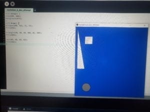
Step 1: Graphic involving 3 different shapes

I kept this first task simple with three different shapes sitting on top a blue background:

void setup() {
size(600, 600);
background(673);
}
void draw() {
ellipse(100, 522, 72, 72);
fill(255);

triangle(18, 18, 18, 360, 81, 360);
fill(204);

rect(81, 81, 63, 63);
fill(102);
}

Step 2: The for loop

After implementing a “for loop” on the code to display the same code 100 times and in different colors and positions, this outcome seemed fairly predictable until comparing this response to the one derived from the draw() loop section. Running the code under the draw section caused images to continuously generate on the screen, whereas running the code under the for loop only performed the task once. This is made even more apparent after looking back at a description on Processing.org, which says “the loop continues until the test evaluates to false,” which would then stop the generation of images in my example rather than continue the process without such a command in play.     

Step 3: Arrays          

Introducing arrays to a code like this one and other more advanced codes is  a drastic improvement in that it helped mitigate the more tedious aspects of the process by eliminating the need to manually enter a collection of previously written values. While the end result is the same when applying arrays to the same original code, it quickly became clear how much time and effort could be saved by beginning a project with an organized data set to return to later.         

Step 4: 

After adding an “if” statement to control the speed at which the different shapes traveled and randomizing some of their sizes I began to recognize how valuable arrays can be in effectively managing larger collections of data where manually altering the behavior of each asset would be overly cumbersome. 

Documentation:  

The main difference between setup() and draw() comes down to the commands they each give to the respective code. draw() operates similarly to a .gif, in that it plays and displays the code given to it almost like how a moview reel quickly flashes image after image to create something that appears to be moving. The setup() function is called only once per sketch and is used for general structuring of the code like size, frame rate, etc. With that distinction in mind, pasting the loop code in draw() as opposed to setup() will cause the loop function the keep restarting until the program itself is stopped. If written under setup(), the loop function will only play once, as it has not been prompted by the continuous recycling found from draw().       

As stated earlier, arrays can have a similarly convenient effect as writing something down in shorthand, but to a higher degree because of the amount of information they can transmit into a few numbers. I bet people who make CGI for movies use a similar strategy when rendering  big crowds of people, or maybe anything that requires a lot of moving parts, but not in a way that necessitates they all be independently and/or singularly dynamic from one another.