Recitation 8: Serial Communication by Bing Chen

In this recitation, I built a circuit that moves an ellipse around on a screen using two potentiometers that acted as knobs. This involved a level of interaction between the user’s movements of turning the knobs and the ellipse moving around in response to that. In addition, I built a circuit that plays a different tone depending on what keyboard letters I was pressing. For each letter pair (a,b) the key pressed a corresponds to the music note b in music. The corresponding pairs are: (s, c), (d, b), (f, a), (g, g), (h, f), (j, e), (k, d), (l, c).  This involves an interaction between the user pressing the keys and the speaker playing the note that corresponds with the keys in response to that.
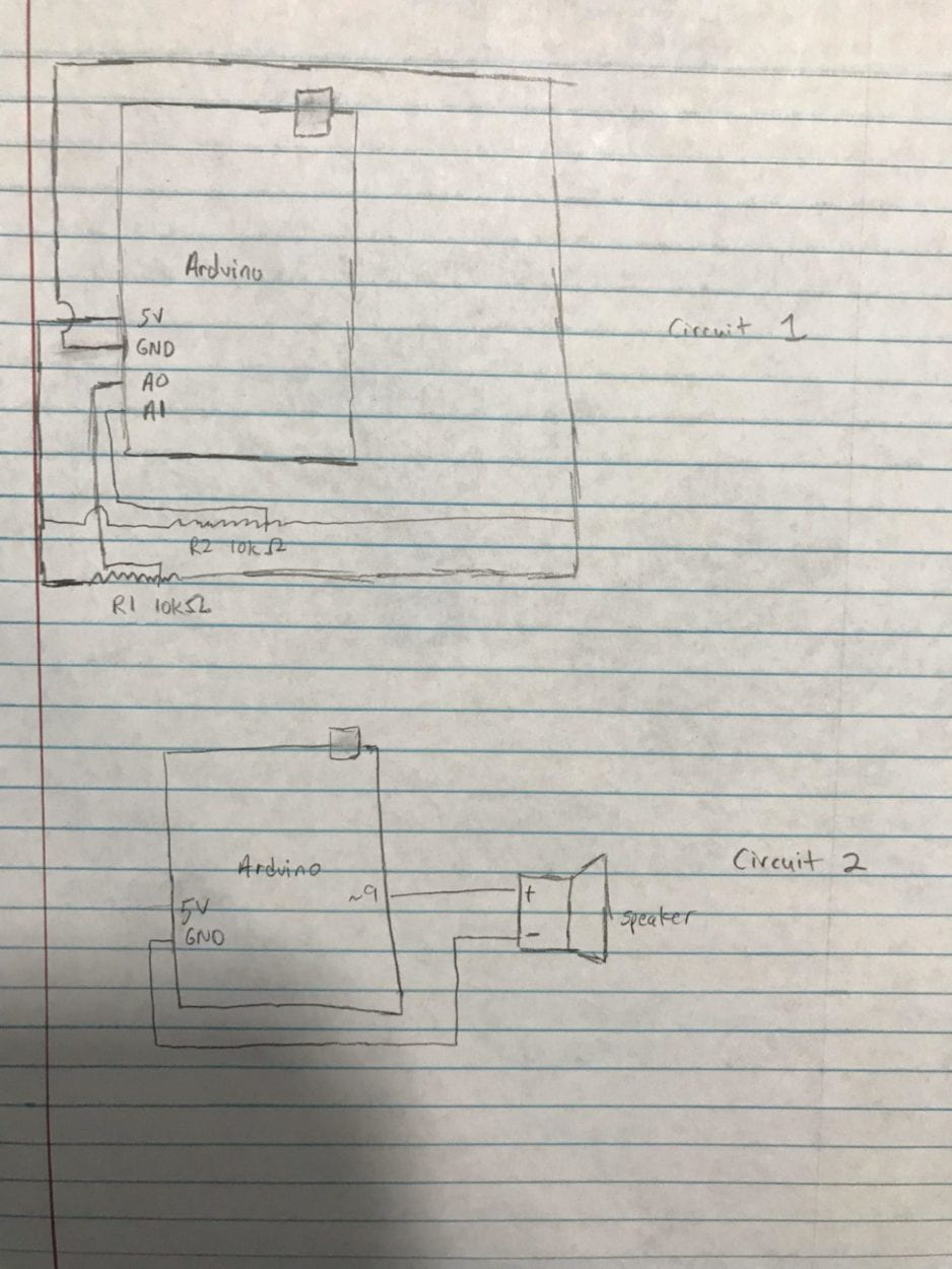
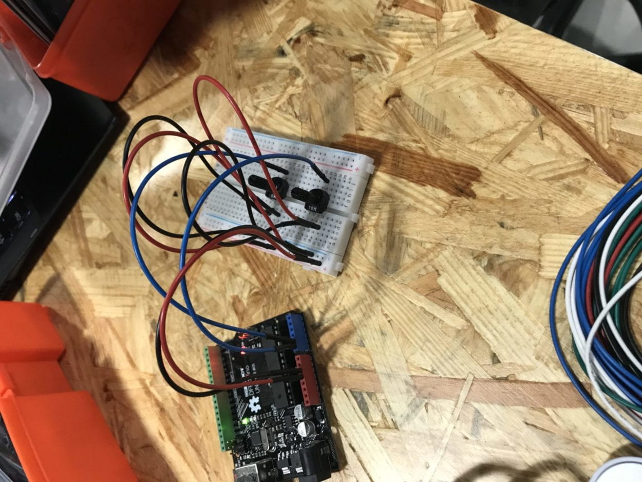
Arduino code for circuit 1:

// IMA NYU Shanghai
// Interaction Lab
// For sending multiple values from Arduino to Processing

void setup() {
Serial.begin(9600);
}

void loop() {
int sensor1 = analogRead(A0);
int sensor2 = analogRead(A1);

// keep this format
Serial.print(sensor1);
Serial.print(“,”); // put comma between sensor values
Serial.print(sensor2);
Serial.println(); // add linefeed after sending the last sensor value

// too fast communication might cause some latency in Processing
// this delay resolves the issue.
delay(100);
}

Processing code for circuit 1:

// IMA NYU Shanghai
// Interaction Lab
// For receiving multiple values from Arduino to Processing

/*
* Based on the readStringUntil() example by Tom Igoe
* https://processing.org/reference/libraries/serial/Serial_readStringUntil_.html
*/

import processing.serial.*;

String myString = null;
Serial myPort;

int NUM_OF_VALUES = 2; /** YOU MUST CHANGE THIS ACCORDING TO YOUR PROJECT **/
int[] sensorValues; /** this array stores values from Arduino **/

void setup() {
size(500, 500);
background(0);
setupSerial();
}

void draw() {
updateSerial();
printArray(sensorValues);

// use the values like this!
// sensorValues[0]

// add your code
background(0);
ellipse(map(sensorValues[0], 0, 1023, 0, 500), map(sensorValues[1], 0, 1023, 0, 500), 50, 50);

}

void setupSerial() {
printArray(Serial.list());
myPort = new Serial(this, Serial.list()[3], 9600);
// WARNING!
// You will definitely get an error here.
// Change the PORT_INDEX to 0 and try running it again.
// And then, check the list of the ports,
// find the port “/dev/cu.usbmodem—-” or “/dev/tty.usbmodem—-”
// and replace PORT_INDEX above with the index number of the port.

myPort.clear();
// Throw out the first reading,
// in case we started reading in the middle of a string from the sender.
myString = myPort.readStringUntil( 10 ); // 10 = ‘\n’ Linefeed in ASCII
myString = null;

sensorValues = new int[NUM_OF_VALUES];

}

void updateSerial() {
while (myPort.available() > 0) {
myString = myPort.readStringUntil( 10 ); // 10 = ‘\n’ Linefeed in ASCII
if (myString != null) {
String[] serialInArray = split(trim(myString), “,”);
if (serialInArray.length == NUM_OF_VALUES) {
for (int i=0; i<serialInArray.length; i++) {
sensorValues[i] = int(serialInArray[i]);
}
}
}
}
}
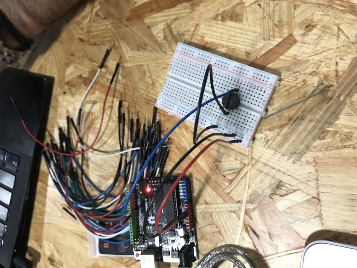
Arduino code for circuit 2:

// IMA NYU Shanghai
// Interaction Lab

/**
This example is to send multiple values from Processing to Arduino.
You can find the Processing example file in the same folder which works with this Arduino file.
Please note that the echo case (when char c is ‘e’ in the getSerialData function below)
checks if Arduino is receiving the correct bytes from the Processing sketch
by sending the values array back to the Processing sketch.
**/

#define NUM_OF_VALUES 8 /** YOU MUST CHANGE THIS ACCORDING TO YOUR PROJECT **/

/** DO NOT REMOVE THESE **/
int tempValue = 0;
int valueIndex = 0;

/* This is the array of values storing the data from Processing. */
int values[NUM_OF_VALUES];
char names [8] = {‘c’, ‘b’, ‘a’, ‘g’, ‘f’, ‘e’, ‘d’, ‘c’};
int tones [8] = {1915, 1700, 1519, 1432, 1275, 1136, 1014, 956};

void setup() {
Serial.begin(9600);
pinMode(9, OUTPUT);
}

void loop() {
getSerialData();

// add your code here
// use elements in the values array
// values[0] // values[1] if (values[0] == 1) {
tone(9, tones[0]);
}
else if (values[1] == 1) {
tone(9, tones[1]);
}
else if (values[2] == 1) {
tone(9, tones[2]);
}
else if (values[3] == 1) {
tone(9, tones[3]);
}
else if (values[4] == 1) {
tone(9, tones[4]);
}
else if (values[5] == 1) {
tone(9, tones[5]);
}
else if (values[6] == 1) {
tone(9, tones[6]);
}
else if (values[7] == 1) {
tone(9, tones[7]);
}
else {
noTone(9);
}
}

//recieve serial data from Processing
void getSerialData() {
if (Serial.available()) {
char c = Serial.read();
//switch – case checks the value of the variable in the switch function
//in this case, the char c, then runs one of the cases that fit the value of the variable
//for more information, visit the reference page: https://www.arduino.cc/en/Reference/SwitchCase
switch (c) {
//if the char c from Processing is a number between 0 and 9
case ‘0’…’9′:
//save the value of char c to tempValue
//but simultaneously rearrange the existing values saved in tempValue
//for the digits received through char c to remain coherent
//if this does not make sense and would like to know more, send an email to me!
tempValue = tempValue * 10 + c – ‘0’;
break;
//if the char c from Processing is a comma
//indicating that the following values of char c is for the next element in the values array
case ‘,’:
values[valueIndex] = tempValue;
//reset tempValue value
tempValue = 0;
//increment valuesIndex by 1
valueIndex++;
break;
//if the char c from Processing is character ‘n’
//which signals that it is the end of data
case ‘n’:
//save the tempValue
//this will b the last element in the values array
values[valueIndex] = tempValue;
//reset tempValue and valueIndex values
//to clear out the values array for the next round of readings from Processing
tempValue = 0;
valueIndex = 0;
break;
//if the char c from Processing is character ‘e’
//it is signalling for the Arduino to send Processing the elements saved in the values array
//this case is triggered and processed by the echoSerialData function in the Processing sketch
case ‘e’: // to echo
for (int i = 0; i < NUM_OF_VALUES; i++) {
Serial.print(values[i]);
if (i < NUM_OF_VALUES – 1) {
Serial.print(‘,’);
}
else {
Serial.println();
}
}
break;
}
}
}

Processing code for circuit 2:

// IMA NYU Shanghai
// Interaction Lab

/**
* This example is to send multiple values from Processing to Arduino.
* You can find the arduino example file in the same folder which works with this Processing file.
* Please note that the echoSerialData function asks Arduino to send the data saved in the values array
* to check if it is receiving the correct bytes.
**/

import processing.serial.*;

int NUM_OF_VALUES = 8; /** YOU MUST CHANGE THIS ACCORDING TO YOUR PROJECT **/

Serial myPort;
String myString;

// This is the array of values you might want to send to Arduino.
int values[] = new int[NUM_OF_VALUES];

void setup() {
size(500, 500);
background(0);

printArray(Serial.list());
myPort = new Serial(this, Serial.list()[3], 9600);
// check the list of the ports,
// find the port “/dev/cu.usbmodem—-” or “/dev/tty.usbmodem—-”
// and replace PORT_INDEX above with the index of the port

myPort.clear();
// Throw out the first reading,
// in case we started reading in the middle of a string from the sender.
myString = myPort.readStringUntil( 10 ); // 10 = ‘\n’ Linefeed in ASCII
myString = null;
}

void draw() {
background(0);

// changes the values
if (keyPressed) {
switch (key) {
case (‘s’): values[0] = 1; break;
case (‘d’): values[1] = 1; break;
case (‘f’): values[2] = 1; break;
case (‘g’): values[3] = 1; break;
case (‘h’): values[4] = 1; break;
case (‘j’): values[5] = 1; break;
case (‘k’): values[6] = 1; break;
case (‘l’): values[7] = 1;
}
}
else {
for (int i = 0; i < values.length; i++) {
values[i] = 0;
}
}

// sends the values to Arduino.
sendSerialData();

// This causess the communication to become slow and unstable.
// You might want to comment this out when everything is ready.
// The parameter 200 is the frequency of echoing.
// The higher this number, the slower the program will be
// but the higher this number, the more stable it will be.
echoSerialData(200);
}

void sendSerialData() {
String data = “”;
for (int i=0; i<values.length; i++) {
data += values[i];
//if i is less than the index number of the last element in the values array
if (i < values.length-1) {
data += “,”; // add splitter character “,” between each values element
}
//if it is the last element in the values array
else {
data += “n”; // add the end of data character “n”
}
}
//write to Arduino
myPort.write(data);
}

void echoSerialData(int frequency) {
//write character ‘e’ at the given frequency
//to request Arduino to send back the values array
if (frameCount % frequency == 0) myPort.write(‘e’);

String incomingBytes = “”;
while (myPort.available() > 0) {
//add on all the characters received from the Arduino to the incomingBytes string
incomingBytes += char(myPort.read());
}
//print what Arduino sent back to Processing
print( incomingBytes );
}

Final Project Research Essay by Bing Chen

For the group project, I defined interaction as “a cyclic process involving action and reaction between two forces.” After everything I learned making my midterm project and experiencing other people’s midterm projects, I’ve extended my definition to “a situation where two people or things communicate or react to each other in a balanced or unbalanced reciprocal manner,” because I realized that the interaction between two forces isn’t always cyclical. The interaction between two forces doesn’t have to be equal, one side could act multiple times before getting a reaction from the other side. Furthermore, one side could exhibit more effort while the other less. 

Going back to my blog post from the group project, I mentioned how the Expressive Tactile Controls project fits my definition of interaction but that is no longer the case. This project might fit in with other people’s definition of interaction or even my previous definition, but it does not fit with my current definition of interaction. That project no longer fits in with my definition because I have extended it to imply that the two forces don’t necessarily need to put in the same amount of effort. In other words, the equilibrium of the human pressing a button and getting an immediate response just seems too basic and primal for me. As soon as the human pushes the button, the mechanism responds. I think it is still interaction to a degree, but not as sophisticated as I think interaction can be. 

A project that aligns more closely with my definition of interaction is the Oh Still My Beating Heart project involving a very accurate infrared sensor that senses the user’s heart-rate. This project might not seem to be interactive on the surface, but it fits into my new definition of interaction to a T because it involves a “situation,” in this case the reading of the user’s heart-rate, “between two people or things,” in this case between a person and an infrared sensor, “communicate,” in this case the infrared sensor is telling the program the user’s heart-rate and the program is passing it on to the user via a monitor,  “in a balanced or unbalanced reciprocal manner,” in this case being unbalanced because all the user needs to do is put his or her finger on the sensor and the program works through a series of circuits and calculations to come up with a result. 

Therefore, my definition of interaction has evolved to something more detailed using influence from the midterm projects of other classmates, researching online projects, and my past group project blog post. Instead of just a cyclic process between two forces, my new definition of interaction is more detailed and involves much deeper thinking. Through my preliminary research into the final project, I am able to walk away with some ideas that could work, given my current definition of interaction, and I look forward to putting it to the test. 

Expressive Tactile Controls

https://www.makeuseof.com/tag/hardware-projects-processing-p5/

Recitation 7: Processing Animation by Bing Chen

Coming into this recitation, I already knew most of the programming features of processing because I have used it before. But in this recitation, I learned how to use the key and keyMode variables, something I never used before. I wanted to make my animation involve keyMode because I wanted more practice coding something different than my usual mousePressed programs. 

Before this recitation, I wanted to create a program similar to the popular carnival game Whack-A-Mole using Object-Oriented Programming. I was going to make a “mole” class called “Disk” and make each disk pop up randomly using the random() function. Unfortunately, this didn’t go as planned because for some reason the Disk class started rejecting all of the processing built-in functions, like fill() and ellipse(). Due to time-constraints, I changed my project to a short game where you control an eraser using the keyboard direction keys and you have to erase the board.

Code for eraser: 

void setup() {
size(600, 600);
background(0);
smooth();

textAlign(CENTER);
textSize(30);
text(“Erase the board as fast as you can!”, 300, 50);

noStroke();
}

// variables for the eraser (rect)
int x = 300;
int y = 300;
int w = 40;
int h = 40;

// how many “I Love Math” to draw
int i = 0;

void draw() {

if (i < 100) { // spam “I Love Math” like there’s no tomorrow
fill(255);
textSize(random(0, 50));
text(“I Love Math”, random(0, 600), random(100, 600));
i++;
fill(0);
}

rect(x, y, w, h); // the eraser

// control the movements of the eraser
if (key == CODED) {
if (keyCode == UP) {
y -= 5;
}
else if (keyCode == DOWN) {
y += 5;
}
else if (keyCode == LEFT) {
x -= 5;
}
else if (keyCode == RIGHT) {
x += 5;
}
}
}

Code for step 4: 

void setup() {
size(1000, 1000);
strokeWeight(10);
frameRate(16);
}

int x = 500;
int y = 500;
int size = 500;
boolean expand = true;

void draw() {
background(255);
stroke(random(0, 255), random(0, 255), random(0, 255));

if (expand) {
ellipse(x, y, size, size);
size += 10;
}
else {
ellipse(x, y, size, size);
size -= 10;
}

if (size == 600) {
expand = false;
}
else if (size == 500) {
expand = true;
}

if (key == CODED) {
if (keyCode == UP) {
y -= 10;
}
else if (keyCode == DOWN) {
y += 10;
}
else if (keyCode == LEFT) {
x -= 10;
}
else if (keyCode == RIGHT) {
x += 10;
}
}
}

MarioDart – Bing Chen – Marcela

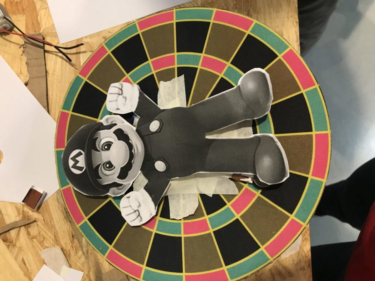
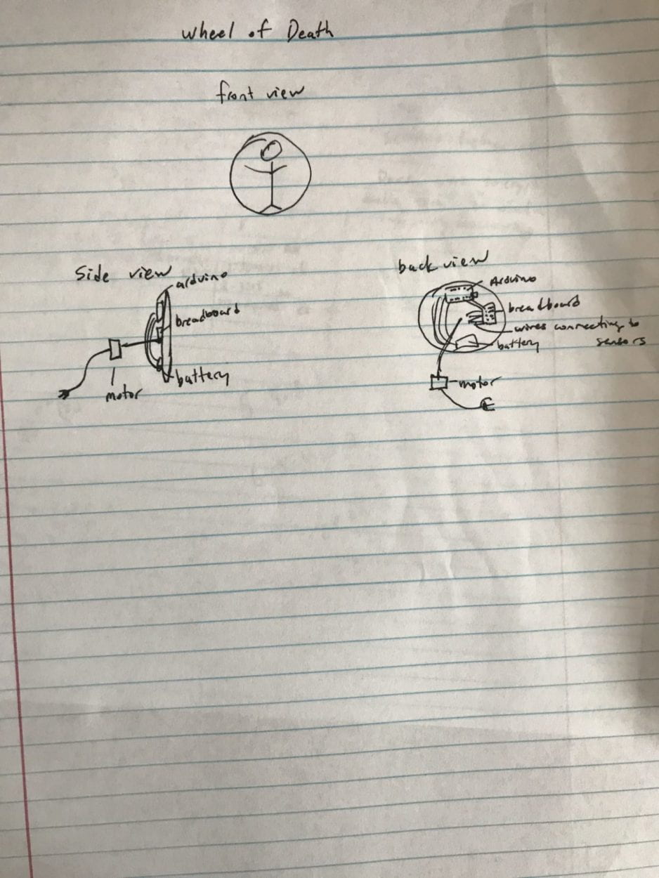
        The inspiration for MarioDarts came from a circus act called the Wheel of Death where a woman is strung to a spinning wheel and a man will throw knives at the wheel without hitting the woman. The decision to go forward with creating something based on this idea came from wanting to do something different from our group project. We thought we would make something more fun and interesting; something that would cause the user to physically interact with it using more than just speech. This is different from our last project (iMirror) because unlike iMirror, this is more like a game. The interaction in iMirror was in communication through human speech because the user can talk with the AI behind iMirror. But the interaction in MarioDart doesn’t require speech at all. Although the users can speak with each other, the interaction in terms of speech is not between the user and the project itself. In addition, whereas iMirror is geared more towards women and adults who wish to take care of their skin, MarioDarts targets a younger audience who are more interested in playing games.

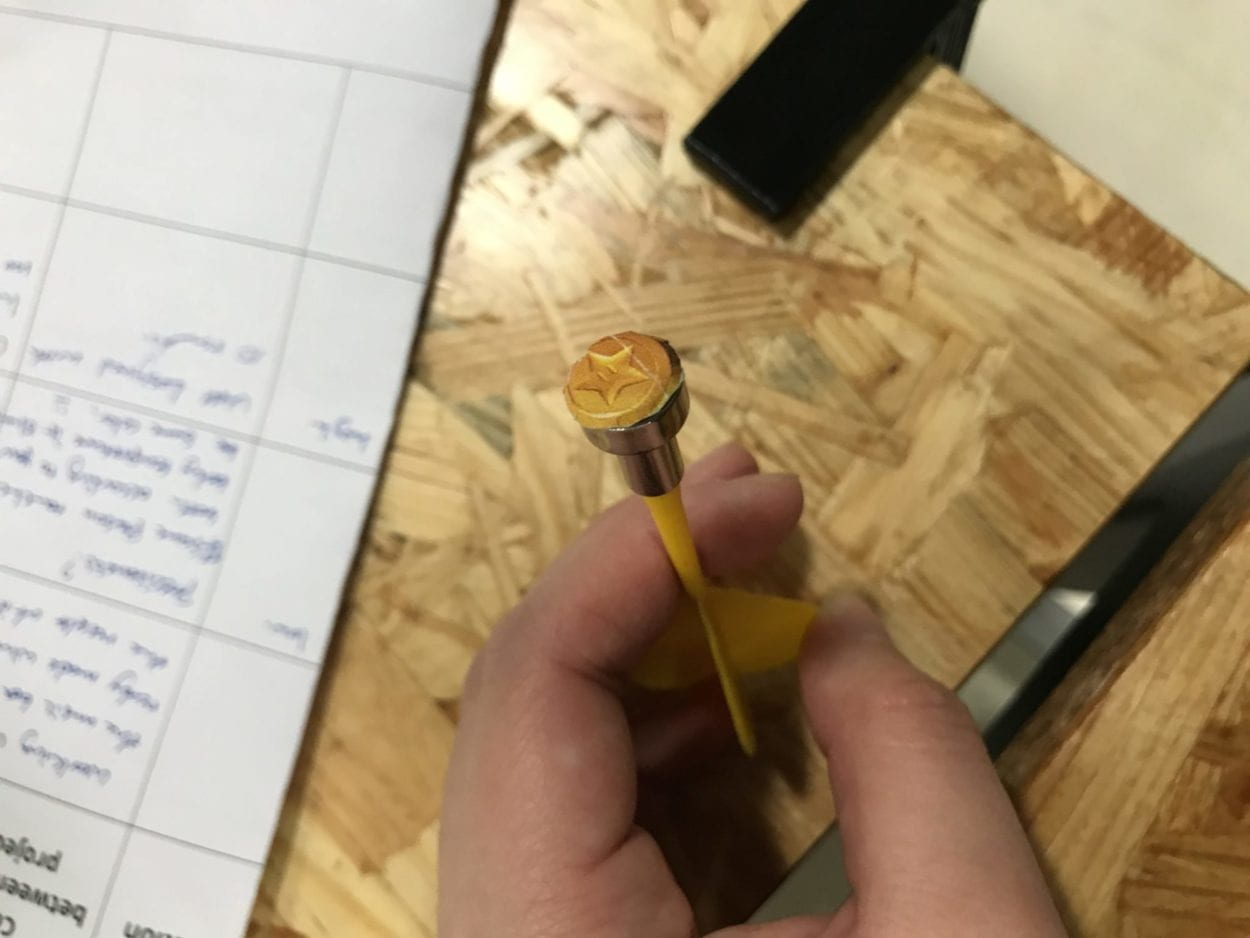
        At first, we wanted to make the purpose of the game to throw darts, representing knives, at a spinning wheel with a person strapped to it but the player has to avoid “stabbing” the person. And when we went into mapping out how and what we were going to use to make the wheel, we tossed around some ideas like velcro or magnets. After our first idea meeting, we decided to start putting together our prototype in the lab. We asked Fellow Nick some questions regarding some issues we thought we would face. Such issues included the possibility that the wires connecting the motor used to spin the wheel would get tangled up once the wheel started spinning. We also wanted to incorporate some sort of sensor into our project, like making the person scream if she was hit. But then we ran into the problem of deciding what kind of sensors to use. Nick suggested a vibration sensor but we didn’t want it to get activated if it senses a vibration from the board itself. We finally decided on a combination of using a magnetic board and force sensors to make our project happen. Another problem we had was how to program a human scream. We ended up programming the first few notes of the Mario theme song instead. Which led us to change the lady on the wheel to Mario as well. 

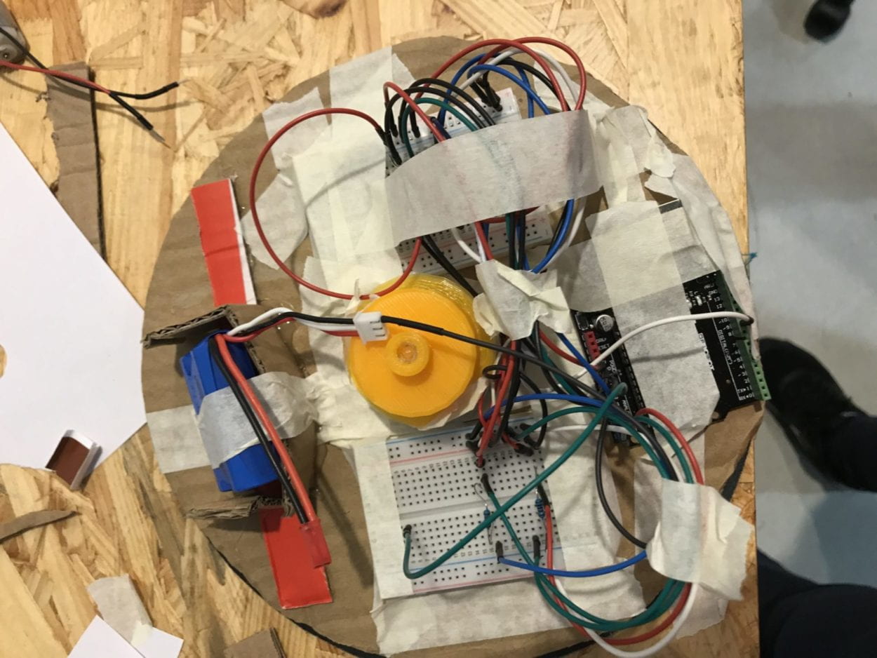
        The first step in putting together our project was everything that we can do for the board/wheel itself. Because we wanted to attach our wheel to a base so the wheel would be spinning while facing the user instead of facing the ceiling, we had to make sure the board, and more specifically the sensors, was working before we attached it to the base. As mentioned before, one of the problems with a spinning wheel is that the wires would get tangled up when it spins. So Fellow Nick suggested that we use two Arduinos, one to power the motor (another problem altogether) and one to power the sensor. In addition, we could put everything that makes the sensors work (the Arduino, wires, separate batteries, and breadboards) onto the back of the board itself. This way the wires won’t be sticking to an external source and be tangled up when it spins. Unfortunately this added on the problem of extra weight, which brings me to the issue we faced with selecting a motor that would spin the wheel. In order, we tried the DC motor (too small to attach to the board), Servo motor (not strong enough), a different Stepper motor the equipment room gave us (something was wrong with it and it wouldn’t program like normal), and finally the Stepper motor. I think if we had started with the Stepper motor we could have avoided wasting a lot of time and now that I think about it, I’m not sure why we didn’t think of it. 

        During the User Testing Session, we got a lot of feedback about the nature of our project. When we set out to make this wheel, we weren’t planning on turning it into a multiplayer game because the original concept was more of a performance than a game. But after seeing the competitive urge this wheel brings up in other people, we thought we should definitely turn it into a game. We also got the feedback that some people might not feel comfortable with “killing Mario,” but we didn’t want to change the character we placed in the middle of the board, so following Marcela’s advice, we put pictures of coins at the end of the darts and changed the purpose of the game. So instead of avoiding hitting the Mario at the center of the wheel, players would be trying to send the “coins” into Mario’s hands, feet, and head so he can collect the coins like he does in the video games.

        The goal of my project is to create a game where more than two players can take turns throwing darts at a spinning wheel to see who can hit Mario the most. This project aligns with my definition of interaction because it involves a reciprocal action-reaction process between the players and the board, where if the player hits the Mario at certain sensor-points, the board will make a sound.  I think at this point in my project, the link between the audience and the sensors isn’t that great because the sensors aren’t that sensitive. So this doesn’t align with my definition of interaction in that it isn’t as complete or act as it should, at this point in time. If I had more time, I would find some way to increase the amount of sensors so the board is more sensitive. I would also find some way to make the magnetic parts of the darts stick to the board more than they fly off. Through the process of making this project I learned many valuable lessons about project planning and design. I learned the importance of planning before executing and the effect the lack thereof has on the creation process. I learned how to use sensors and motors collectively to accomplish a final goal. I also learned the importance of teamwork and the value of other people’s opinions and suggestions. I will keep all of these in mind as I go into my final project in a few weeks time.

[code for the sensor]

// Sensor and output
int senRd1 = 0;
int senRd2 = 0;
int senRd3 = 0;
int senRd4 = 0;
int senRd5 = 0;
boolean personHit = false;
int speakerPin = 9;

// define notes for melody
#define REST 1
#define NOTE_B0 31
#define NOTE_C1 33
#define NOTE_CS1 35
#define NOTE_D1 37
#define NOTE_DS1 39
#define NOTE_E1 41
#define NOTE_F1 44
#define NOTE_FS1 46
#define NOTE_G1 49
#define NOTE_GS1 52
#define NOTE_A1 55
#define NOTE_AS1 58
#define NOTE_B1 62
#define NOTE_C2 65
#define NOTE_CS2 69
#define NOTE_D2 73
#define NOTE_DS2 78
#define NOTE_E2 82
#define NOTE_F2 87
#define NOTE_FS2 93
#define NOTE_G2 98
#define NOTE_GS2 104
#define NOTE_A2 110
#define NOTE_AS2 117
#define NOTE_B2 123
#define NOTE_C3 131
#define NOTE_CS3 139
#define NOTE_D3 147
#define NOTE_DS3 156
#define NOTE_E3 165
#define NOTE_F3 175
#define NOTE_FS3 185
#define NOTE_G3 196
#define NOTE_GS3 208
#define NOTE_A3 220
#define NOTE_AS3 233
#define NOTE_B3 247
#define NOTE_C4 262
#define NOTE_CS4 277
#define NOTE_D4 294
#define NOTE_DS4 311
#define NOTE_E4 330
#define NOTE_F4 349
#define NOTE_FS4 370
#define NOTE_G4 392
#define NOTE_GS4 415
#define NOTE_A4 440
#define NOTE_AS4 466
#define NOTE_B4 494
#define NOTE_C5 523
#define NOTE_CS5 554
#define NOTE_D5 587
#define NOTE_DS5 622
#define NOTE_E5 659
#define NOTE_F5 698
#define NOTE_FS5 740
#define NOTE_G5 784
#define NOTE_GS5 831
#define NOTE_A5 880
#define NOTE_AS5 932
#define NOTE_B5 988
#define NOTE_C6 1047
#define NOTE_CS6 1109
#define NOTE_D6 1175
#define NOTE_DS6 1245
#define NOTE_E6 1319
#define NOTE_F6 1397
#define NOTE_FS6 1480
#define NOTE_G6 1568
#define NOTE_GS6 1661
#define NOTE_A6 1760
#define NOTE_AS6 1865
#define NOTE_B6 1976
#define NOTE_C7 2093
#define NOTE_CS7 2217
#define NOTE_D7 2349
#define NOTE_DS7 2489
#define NOTE_E7 2637
#define NOTE_F7 2794
#define NOTE_FS7 2960
#define NOTE_G7 3136
#define NOTE_GS7 3322
#define NOTE_A7 3520
#define NOTE_AS7 3729
#define NOTE_B7 3951
#define NOTE_C8 4186
#define NOTE_CS8 4435
#define NOTE_D8 4699
#define NOTE_DS8 4978

// Sample code for Mario melody is from:
// https://www.instructables.com/id/Play-Custom-Melodies-on-Arduino/
// by JmsDwh

// notes in the melody:
int Mario_melody[] = {
NOTE_E4, NOTE_E4, REST, NOTE_E4,
REST, NOTE_C4, NOTE_E4, REST,
NOTE_G4, REST, REST, NOTE_G3, REST,
};

int Mario_Notes[] = {
4, 4, 4, 4,
4, 4, 4, 4,
4, 2, 4, 2, 2,

};

const int num_elements_in_arr = sizeof(Mario_Notes)/sizeof(Mario_Notes[0]);

void setup() {
pinMode(speakerPin, OUTPUT);
}

void loop() {
// reading any inputs
senRd1 = analogRead(A0);
senRd2 = analogRead(A1);
senRd3 = analogRead(A2);
senRd4 = analogRead(A3);
senRd5 = analogRead(A4);
senRd6 = analogRead(A5);

// if any sensor is hit
if (senRd1 > 0 || senRd2 > 0 || senRd3 > 0 || senRd4 > 0 || senRd5 > 0) {
personHit = true;
}

// play melody
if (personHit) {
playMelody();
personHit = false;
}
}

// code by JmsDwh
void playMelody() {
// iterate over the notes of the melody:
for (int thisNote = 0; thisNote < num_elements_in_arr; thisNote++) {

// to calculate the note duration, take one second
// divided by the note type.
//e.g. quarter note = 1000 / 4, eighth note = 1000/8, etc.
int noteDuration = 500/Mario_Notes[thisNote];
tone(speakerPin, Mario_melody[thisNote],noteDuration);

// to distinguish the notes, set a minimum time between them.
// the note’s duration + 30% seems to work well:
int pauseBetweenNotes = noteDuration * 1.30;
delay(pauseBetweenNotes);
// stop the tone playing:
noTone(speakerPin);
}
}
[/code for the sensor]


[code for stepper motor] // Spins the wheel at a slow speed
#include <Stepper.h>

const int stepsPerRevolution = 200; // change this to fit the number of steps per revolution
// for your motor

// initialize the stepper library on pins 8 through 11:
Stepper myStepper(stepsPerRevolution, 8, 9, 10, 11);

void setup() {
myStepper.setSpeed(10);
}

void loop() {
myStepper.step(stepsPerRevolution);
delay(1);
}
[/code for stepper motor]

Recitation 6: Processing Basics by Bing Chen

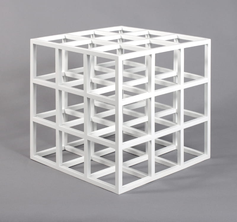
Below is the image I chose to model my design after called: Untitled (Cube) (1979) by Sol Lewitt

(https://blogs.uoregon.edu/sollewitt/2004/02/19/untitled-cube-1979/)

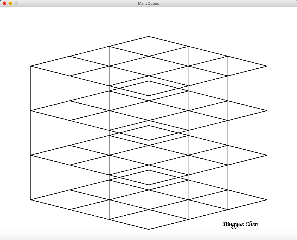
I chose this image because this image is simple yet mesmerizing. The way all the inner cubes mesh together so that it becomes difficult to tell which line belongs to which cube is fascinating, which is why I decided I wanted to draw this model using Processing. 

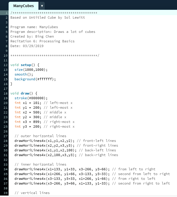
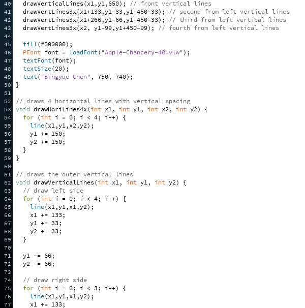
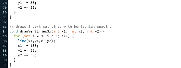
Going into this, I noticed how I can draw many of the lines using the same code. This led to me to the decision to use loops so I wouldn’t have to code every line I wanted drawn (because computer programmers are lazy, it’s true). Then I realized I could use the same code for the loops to draw the next group of lines, so maybe I should use a nested loop. But I opted to make my own functions instead. I created a function to draw all the horizontal lines from top to bottom for one level and a function to draw all the vertical lines from left to right. And another function to draw the vertical lines on the outside (although I probably could have used the other functions to do this instead but I wrote this part first so didn’t think of it).

My final creation is similar to the motif in that the basic shape is exactly as the original. It is different than the original because the original is a model and this is a drawing using only lines. In a way, this is even harder to look at because the lines collage together even more than the original model. I think using Processing was a good tool for realizing my design because I don’t think I would have wanted to create the design using real life models because I am a programmer and I like to stick to my roots.