Materials
- 1 * Arduino Uno
- An open-source platform used for building electronics projects.
- 1 * USB A to B cable
- Connects Arduino to computer
- 1 * breadboard
- A base for holding and connecting the components
- 1 * buzzer
- Create sound when the current flow
- 2 * LEDs
- Light when the current flow
- 2 * 220 ohm resistors
- Create resistance in the flow of electric current
- 2 * 10K ohm resistors
- Create resistance in the flow of electric current
- 2 * pushbuttons
- When pressed, it allows current to flow
- 2 * arcade buttons
- When pressed, it allows current to flow
- A handful of jumper cables
- Connect the components
- 1 * Multimeter (optional)
- Used to measure resistance.
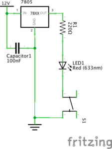
Circuit 1: Fade
Process:
While we were building the first circuit, we made two mistakes that made our circuit failed to function. We arranged the resistor horizontally, which doesn’t make sense since the holes are connected horizontally on the breadboard; therefore, the LED didn’t light. After we fixed this problem, the LED worked but the lightness was really low, so we called Nick for help. Nick told us, the reason of the dim light was the ohm of the resistor, since it created too much resistance in the flow of the current. Therefore, what we should do was to use the multimeter to measure the ohm of resistors, and make sure that we use the right one, which is the one with 220 ohm. We followed his instruction, and found out that we did mistakenly installed the wrong resistor. Afterward, we changed the resistor, and successfully made the circuit worked.
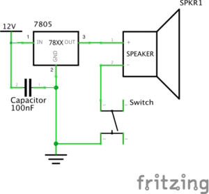
Circuit 2: toneMelody
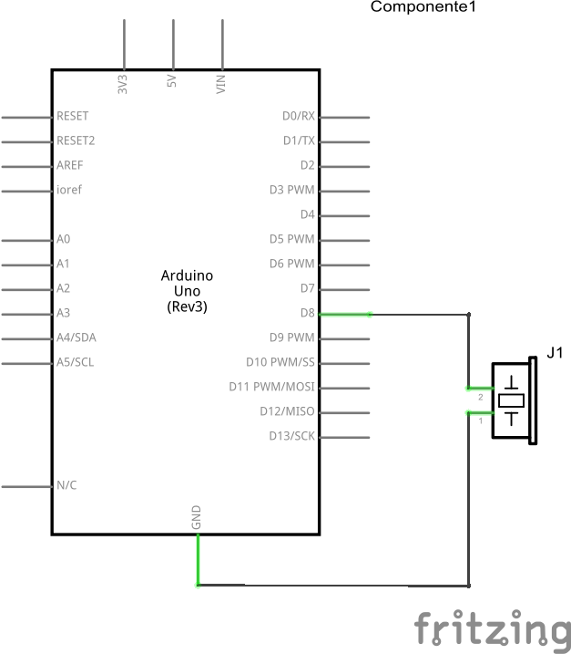
Process:
Since the structure of the circuit was relatively simple, it only took us few minutes to complete the circuit. Then, we called out the code from “file” → “examples” → “digital” → “toneMelody”, and uploaded it into the Arduino board. Throughout the whole process, we didn’t encounter any difficulties, and circuit worked perfectly in our first try.
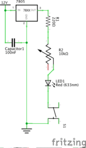
Circuit 3: Speed Game
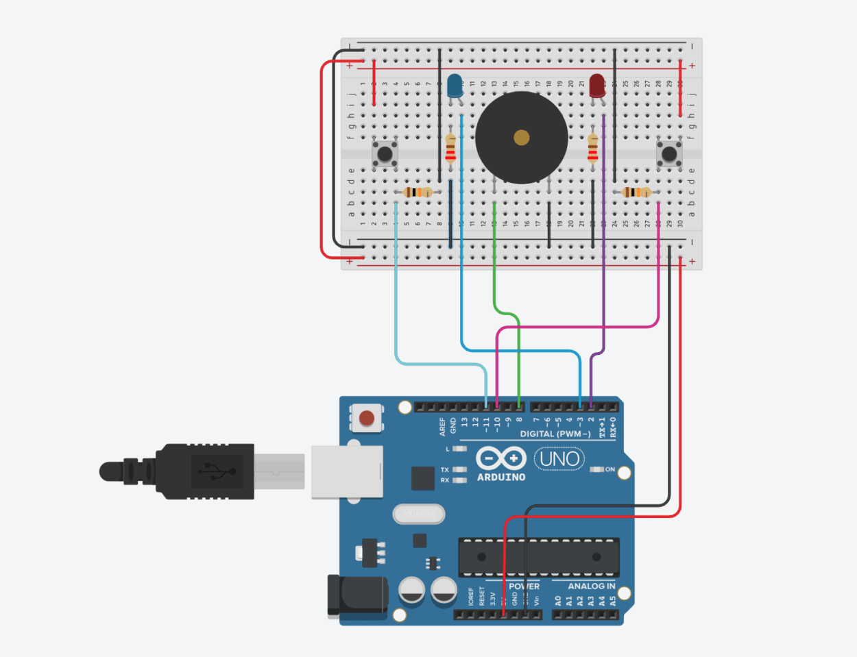
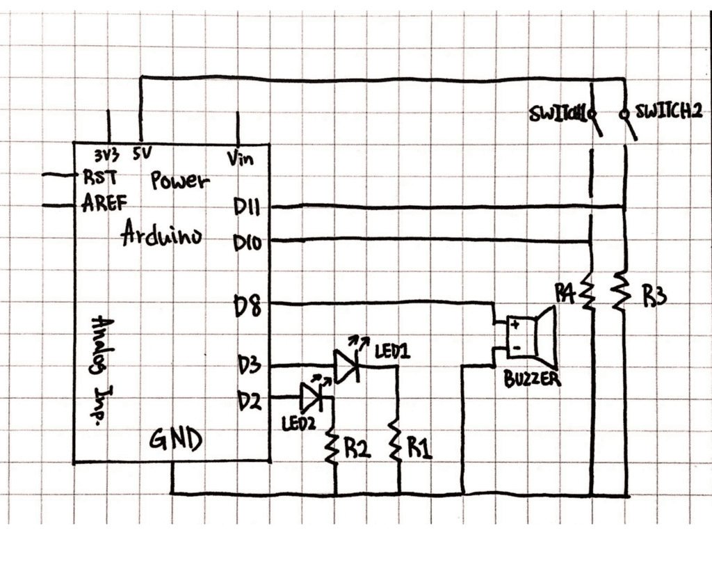
Process:
The structure of the circuit was more complicated than the previous ones. We completely follow the picture to arrange and connecte the components. However, when we upload the code into Arduino, the circuit didn’t work well. First, there were problems with one of the buttons because it sometimes didn’t plus one to the record when pressed. Second, the LED didn’t light up when the game was finished. Since there were too many problems with the circuit, we thought we should start all over again. Therefore, we reconstructed all of the components by following the picture. We even made sure that our board was in the same direction as the picture shown. But unfortunately, the same problems occurred and we still had no idea how to fixed them. At the end of the recitation, which was when most students already left, we asked Rudi for help. Instead of following the picture, he said we should simplified the circuit. He took some jumper cables out, and directly installed legs of the resistors into the bus area of the breadboard. Furthermore, before we upload the “Speed Game” code, he said we should check if each component is able to work. He called out the “blink”, “toneMelody” and “DigitalReadSerial” codes to check the components one by one. After we made sure that all of the components worked, we upload the “Speed Game” code into Arduino, and the circuit finally worked.
Questions
Reflect how you use technology in your daily life and on the circuits you just built. Use the text Physical Computing and your own observations to define interaction.
I started my day with turning off alarm from my cellphone and checking the time and weather. Afterwards, I need to swipe my card before I leave the dorm, and do it again before I enter the campus. Within the first two hours of my day, I already interacted with three devices. Therefore, for me, it seems like it’s nearly impossible to live without technology. Although we have been immersed in a world that consist so many different types of machines, these machines all follow the processes of input to output, just like the circuits that we built. For the circuits that we built, the input is the code that we uploaded into Arduino, and the output is the fading light or sounds created by speaker. According to Physical Computing, interaction, in computer terms, can be defined as iterative process of “input, processing, and output.” Therefore, the processes of the circuits I mentioned can be defined as interaction.
If you have 100,000 LEDs of any brightness and color at your disposal, what would you make and where would you put it?
If I have 100,000 LEDs, I would want to create LED wallpapers by installing them on the walls and ceiling of my bedroom. By doing so, I’m able to change the wallpapers at anytime I want. For example, before I go to sleep, I can change the blank ceiling into starry night sky. Furthermore, LED wallpapers can also function as moveable wallpapers. For instance, I can create a raining scene inside my room, and I can also connect the wallpaper to my computer/phone, in order to have a bigger screen to watch movies and dramas.