Introduction
In this two part project, my partner and I were tasked with creating three different circuit boards while simultaneously soldering a wire to an arcade button which was planned to be used in circuit number three. The goal of circuit one was to transfer electricity from the 12 voltage power supply to the doorbell and produce a sound. Circuit two took a similar form in terms of schematics, but was instead used the volts to power an LED light rather than a doorbell. Although we did not finish the third circuit in time, the objective was similar but instead was intended to power a dimmable lamp. I came into this project with little background about electrics or wiring so I had many goals in mind but only a few stuck out. First, I wanted to have a comprehensive baseline knowledge of working with a breadboard in order to feel comfortable in later projects. By knowing the ins and outs of a breadboard, I felt as though it could thoroughly prepare me for anticipating future issues within my projects. My other goal was safety. With loose knowledge of circuit boards, I choose to act on certain knowledge rather than guessing when inserting wires and connecting the circuit together. Especially in regards to soldering, I was sure to take it slow and ask for the professors help in any scenario where I was unsure. Although I inputted some wires out of order, and partner and I made sure to quickly extinguish any existing problem before it become a serious safety issue. All resources used for this project were borrowed from the IMA lab in room 826/825 at NYU in Shanghai.
Circuit One
Initially, my partner and I plugged the 12 volts into the breadboard in the first row of the +- column. By doing so, it activated the board and gave it un-directed voltage. To direct this flow of voltage, we inserted the LM7805 voltage regulator into rows e10-e11-e12 of the breadboard. We then took a red wire and connected it to d10 which corresponded with prong one of the LM7805 regulator. The other end of the red wire was then put into the positive column of the breadboard, corresponding with the original red wire from the 12 volts plugged in first. A blue wire was then plugged into a12 to correspond with input two of the LM7805 regulator. The other end of the blue wire was the plugged into the negative column in line with the negative 12 voltage wire. Thus, power had been given to the LM7805 voltage regulator in the first two prongs. A picture of our first steps can be found below. 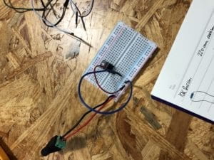 Following these initial steps, my partner and I then incorrectly placed the switch on the edge of the negative column and in rows a15 and a17. This made it impossible for the switch to receive both negative and positive voltage which therefore caused a defunct speaker with no sound later in the process. A picture of the incorrectly placed switch can be viewed below.
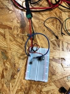
After consulting Professor Lee, we quickly realized our mistake and rearranged the button configuration. We placed it on rows a/d20 and a/d22 near the bottom of the board to allow for adequate space between wires. We then inserted a wire on row e22 which corresponded to the negative column. After this was completed, my partner and I inserted the speaker on row 15 and 12 (to correlate with the LM7805) and placed a wire from row a15 to row e20 (the other end of the switch). By doing so, we successfully connected the switch to the speaker. Before finishing the circuit, we inserted a 100nf capacitor on rows c4 and c6. We then completed the wiring from row a4 to the positive column and from row a6 to the negative column in order to receive the necessary electricity. A picture and video of the completed circuit can be viewed below. 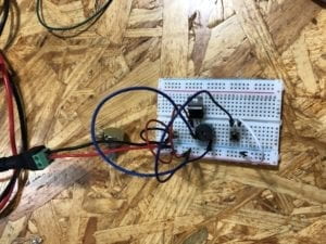
The video of the completed circuit is linked above.
Circuit Two
My partner and I found circuit two easier to build because the initial base was a reflection of what we built in circuit one. However, we unplugged everything before realizing this. So, we duplicated the original structure of the LM7805 configuration by linking prong one to the 12 voltage power source and using the same rows (e10-e11-e12) for it’s area. Prong one correlated with the positive 12 voltage source and prong two correlated with the negative 12 voltage source. My partner and I then linked the 100nf capacitor (c5 and c4) with the 12 voltage power source by using a wire from b5 to the negative column and another from b4 to the positive column. We also placed the button in the same rows (b/e22 and b/e24) and inserted the corresponding wires. A white wire was placed from row a22 into row b20. After taking care of the duplication process for the first two prongs of LM7805, it was time to begin the restructuring to use an LED light rather than a speaker. So, in order to do this, we used a 220 ohm resistor and placed it rows c14 and c17. We then used a wire to connect the resistor at d14 with output three c12 on the LM7805. By doing so, we linked the power of the original 12 volts through to the LM7805 and into the resistor. We then inserted the final piece, an LED light, in rows a17 and a20. This was done so the LED would correspond with the white wire (b20) which connected to the button (a22). The other end of the LED was placed on a17, the same row as the 220 ohm resistor (c17). A picture below can be used for reference to the completed circuit.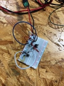
A video showing the completion of the LED circuit two can be found below also.
Soldering
After the completion of circuit two, my partner and I participated in the soldering workshop. Professor Cossovich took us through step by step the precautions needed to use the soldering machine. After reviewing the material provided by Professor Cossovich, we began the process. After waiting for five minutes, we asked Professor Cossovich and he recognized that the machine was not properly functioning. He took us to a new machine and showed us what the proper signs to look for were. Before turning it on again, we placed the wire in the clasp to prepare for soldering. My partner then used the soldering pen to solder one end of the wire to the arcade button. Below is a picture of the finished product on one side. 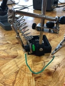 After finishing the first side, I used the soldering pen to attach another wire to the other side of the arcade button. The overall process took about 5-6 minutes. A picture of the finished soldering can be viewed below.
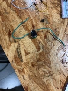
Unfortunately, as soon as we picked it up, the soldered wire snapped off from the arcade button on both sides. This caused us to re-do the entire process. But as a result, we were far more detailed and used more of the soldered wire to create a solid merging between button and wire. This concluded the soldering portion of the recitation.
Circuit Three
My partner and I had left half of circuit two unfinished before we went to the soldering workshop because circuit two carried the same base circuit configurations as circuit three. What I mean by base configurations is the LM7805 prong one and two corresponding with the same spots and being wired to the 12 voltage power and the ground. Unfortunately because we used up such a great amount of time soldering the wires to the arcade button twice, we ran out of time in the recitation to finish circuit three.
My Reflection
For the most part, the process proceeded as planned except for a few minor bumps throughout. Although we did not complete circuit three as planned, I still achieved my two goals of learning the basic skills of setting up a breadboard and also ensuring the safety of my partner and I. By achieving these goals, I think it matured my ability and confidence to handle hot materials (soldering) and configure a bread board in a quicker fashion next time. The successful aspects of the project were building circuit one and two. The unsuccessful part revolved around the soldering and the incompletion of circuit three. At first the machine did not work which we can successfully mark down as machine error (attested by Professor Cossovich). I am never glad a mistake happens, but breaking the soldering after handling it in such a tender manner helped me realize that we needed to be more detailed when using the soldering pen next time. The soldered button was going to be a vital part of the process in circuit three which underlines the importance of doing it right the first time. In the future, I think using the professor to help more when we are completely unsure about something can be a useful tool. My partner and I were hesitant to ask for help when soldering which led to the ultimate demise of our soldered wire and button. My learning revolved around understanding how to cooperate with a partner and share the work. By taking turns using the breadboard and soldering material, it gave both of us a chance to truly learn and understand the process first hand. This helped me achieve my first goal of understanding a baseline of using the breadboard. Overall I learned far more than I thought I would and enjoyed having a partner and professors to answers my questions throughout the process.
Questions
- The circuits my partner and I built today were a simple, yet fundamental project in which voltage was transferred into the sound of a doorbell or the power to light a small LED light. I think the interactivity of the project came at the completion when my partner would press the button and a sound was produced as a result. So in simplest terms, the interactivity came through the input of pressing the button and the output of producing sound. All of this was translated through the wires we plugged in and situated to transfer voltage to the doorbell. Circuit 2 took a similar structure in terms of wiring and again was interactive through the act of pressing a button as an input and turning on the LED light as an output. We had no time to complete project 3 so it was left unfinished before we could continue.
- Through what I have personally witnessed, interactive design is commonly used in the art space through sensors. I had the privilege of visiting Island 6’s art gallery here in Shanghai in the M50 district. Island 6 uses LED lights and sensors to use the observer as a part of the art. My favorite example is the “Beryllium Bionic Bears (铍仿生熊)” In the middle of Island 6’s gallery sits a sculpture of a small bear which can be viewed in the link above. The bear’s parts are made up of a stainless steel structure, IR sensors, an 8-bit microcontroller and powered speakers. As one moves in front or around the bear, it begins to growl for 5-10 seconds. This goes on until one steps away and out of range of the sensors. This is an example of interactivity between the viewer and the sculpture in this case. Until one steps within range, the sculpture is just a still representation of a bear. But after the sensors are triggered, the art comes to life and resembles the sounds of a real bear. This is owing to the fundamental input (motion) from the viewer and the output of sound from the bear. A second example of this is Island 6’s “Dao of the Bush Sparrow.” In this piece, LED birds are displayed on top of a stagnant background. The piece is equipped with a sound sensor which when activated, causes the birds to disperse from their original position. This case illustrates a separate approach through sound rather than motion. After clapping occurs, the birds fly away. But once it is silent again, they return to their original position. It is a call and response form of input (the clapping sounds) and output (the birds flying away). All credit in this paragraph and use of work goes to Island 6 Gallery [https://island6.org/ledart].