Recitation 5: Processing Basics by Alexander Cleveland

Deciding on a Motif

When considering the different motifs available to me, many of the faces and masks stood out. First, I used The Art of Computer Design as my guide in the process. Naturally I’ve loved animals for most of my life so after scanning through the pages, I found myself drawn to the goat, fox, and tiger drawings. Below are the three images that I initially sourced my inspiration from. All three images are sourced from The Art of Computer Design.

“Fox”

“Goat”

“Tiger”

I found it especially intriguing how the artist took such basic lines and shapes to form the animals. The fox almost looks like it’s wearing sunglasses, but then again it more-so looks like a fox. The symmetry of the image is also helpful in creating a consistent and clear image for the audience to understand. I think what marks these as great pieces is that even without the title I could most likely tell that they were animals. 

After carefully considering these images, I thought about what was most prevalent in life. What symbols did I see everyday? A dragon. In Chinese society, the dragon is a symbol of good luck and power. And seeing that it is everywhere made it an easy choice to try and emulate. I searched around on the internet and found two images that showcased different aspects of the Dragon motif.

The first image is more traditional in China and used for festivals such as 端午节 (dragon boat festival), 春节 (Spring Festival), or just for overall decor. 

Sourced from Astrology Bay

I liked this image because of the simplicity of the color scheme, similar to the other animals I first looked at. I think it gives off a powerful look which can also showcase the detail put into the symbol. I also appreciate the authenticity of the dragon in detail. The artist didn’t try and do too much to over-detail the frame or the dragon itself. It’s a Chinese dragon, nothing more and nothing less. But, I also wanted to incorporate some more color into my own motif so I looked elsewhere for inspiration. The following image is a less traditional color painting of a Chinese dragon.

A painting sourced from Mark Stopke

I enjoyed this image too because it differentiates current day from traditional. It’s not so much a traditional motif as it is a creative piece of art. The colors are certainly untraditional which I also like. It almost looks as though the dragon is flaming around the mouth and underbelly compared tp the rest of its skin. The color contrast creates an incredibly interesting subject compared to the more traditional motif. Each piece has its own strengths, so I decided to pull colorful inspiration from the second image and traditional schemes from the first image. 

My Own Process

It was difficult at first to find a starting point. I wanted something similar to a dragon, but wasn’t sure how to find the sweet spot between the two images in combo with my own processing abilities. Seeing as I had never used processing before, I decided to create an abstract design of the dragon to the best of my abilities. The image can be viewed below.

“Dragon”

It doesn’t carry the same artistic ability as the images above, but I felt as though I achieved something similar to the initial images I used for inspiration. To start, I tinkered with making squares for the eyes. I had to troubleshoot and guess a little for the initial measurements, but after understanding these I aligned them in a row. I then added the background color of white by inserting background “(255);”. I thought this was a good color selection in order to authentically pop the eye color in contrast. Just as had been done in the second dragon image. After, I added the two ellipses within each square and colored them red to have a similar symbol of power. Red, especially for eyes is menacing in my view. Following the ellipses, I added another square for the nose and two more ellipses within that square for nostrils. Normally I wouldn’t have added nostrils, but in many dragon paintings and symbols there is usually steam coming out of their nostrils so I decided to adjust my motif accordingly. To get the interesting color pop I was looking for, I picked a random color of hot pink/purple. I think it throws the audience off and creates a disco feel to the dragon. Now that I understood how to create dimensions of a square, creating the rectangle for the mouth was easier. I used a black background because one again, I think it represents a menacing figure with a never ending black hole for a mouth. And I choose red for the tongue because it draws attention through a color contrast. When I see this image, I want to look everywhere because each color and shape represents something so unique. The left eyebrow is a result of my incoherency in processing. As the recitation was running out of time, I wanted to add an unorthodox flair to the image by undermining the symmetry. I don’t necessarily like how the eyebrow looks now, but it does represent my goal of uniqueness.

A Good Medium for Artwork

The code for my processing work can be viewed below.

I feel that using processing for explaining my motif was a good start to the design work. I think for simplicity purposes, it showcased the raw edge of my art work. Because I was limited in such a skill set, I felt that it almost made my piece look more aggressive. I enjoyed using it because it limited my ability in the process. By this I mean that for the sake of creating something powerful, yet simple, processing was the perfect medium for my art.

Sources

https://drive.google.com/file/d/17Y-OfpFE_H20WyCjn07dyO_XvjSWO_gN/view 
(The Art of Computer Design)

https://astrologybay.com/blue-dragon-in-chinese-astrology

https://pixels.com/featured/chinese-dragon-mark-stopke.html

Recitation Four: Drawing Machines by Alexander Cleveland

Introduction:

In recitation four, I created three different circuits with the addition of a stepper motor and a 12 VDC power source. The first circuit involved starting the motor with the help of an h-bridge to direct different forms of power and voltage from the Arduino. The second circuit carried the same base as the first, with the exception of an added potentiometer. The goal of this circuit was to control the movement of the motor rotor with the potentiometer. After working alone on the first two circuits, the goal of circuit three was to link up with a partner and create a joint drawing machine. This machine was powered by two motors that both my partner and I individually created in circuits one and two. My specific goals for this recitation were as follows: 1. To get through the recitation without short circuiting my Arduino board. This is imperative to my success and confidence in future recitations that I complete all circuits without misplacing a voltage or ground power source. 2. To safely complete the three circuits without any damage to myself or my partner. This has been a goal in all of my recitations, but especially with the 12 Volts being newly introduced today. 3. Lastly but not least, ask for help when I need it. In past recitations I had made a habit of trying to do it myself when I didn’t know something out of pride. But in these circumstances, I did not want a simple error lead to compromised safety for me or my partner. All resources used for this project were borrowed from the IMA lab in room 826/825 at NYU in Shanghai and also from my own Arduino kit handed out at the beginning of class. The materials used for this recitation are as follows:

For Steps 1 and 2

1 * 42STH33-0404AC stepper motor
1 * L293D ic chip
1 * power jack
1 * 12 VDC power supply
1 * Arduino kit and its contents

For Step 3

2 * Laser-cut short arms
2 * Laser-cut long arms
1* Laser-cut motor holder
2 * 3D printed motor coupling
5 * Paper Fasteners
1 * Pen that fits the laser-cut mechanisms
Paper

(Material list provided by NYU Shanghai IMA Department)

Circuit One

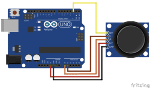
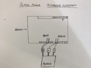
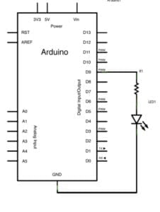
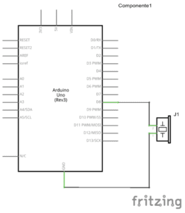
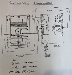
As I eluded to in my introduction, the goal for circuit one was to create a workable base for circuit two and three. This mean’t simply activating the stepper motor. In order to do so, I need four essential tools besides the Arduino and breadboard. These tools included a 12 Voltage power source to run the motor (because 5 Volts for the Arduino is not enough in this case), a stepper motor, a power jack, and a L293D ic chip (I will refer to it as an H-bridge throughout the rest of this documentation). In order to keep the wire clutter to a minimal, I first placed the H-bridge towards the bottom of the breadboard. This ensured that when I add the potentiometer in circuit two, there would be ample room to install the surrounding wires. Below is a picture of the planned circuit with the Arduino board on the left, the H-bridge in the center, and the stepper motor on the far right. All credit goes to NYU Shanghai for providing the diagram.

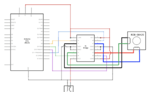
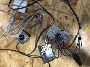
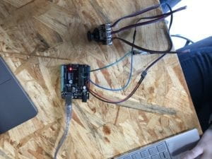
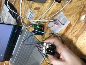
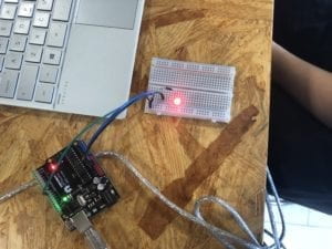
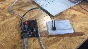
In order to facilitate ease when plugging wires into the power and 5 V sources, I linked a red wire from the positive column of the breadboard to the 5 V on the Arduino board. I also linked a black wire from the negative column of the breadboard to the ground power source on the Arduino board. What follows is a series of wire linkages from the 16 ports of the H-bridge to the Arduino board, the stepper motor, and 12 Volts power source. First, I linked port one (1,2 EN) with the positive column of the breadboard. I then linked port two (1A) to Digital 8 pin on the Arduino board. After, I matched a black wire from port three (1Y) to the black wire port (A) in the stepper motor. After, I matched ports four and five (GND 1 and GND 2) with the negative column to link them back to ground power on the Arduino board. I then linked port six (2A) with the green wire port (C) of the stepper motor. I followed this by linking port seven (2A) with digital pin ~9. To round off the left side, I connected the red wire (positive) of the 12 V source to port eight (VCC2) on the H-bridge. The next linkages start from the bottom right of the H-bridge.  I connected port nine (3,4 EN) to the positive column in order to link it with 5 Volts of power. I then linked port ten (3A) to digital pin ~10. After, I linked port eleven (3Y) to the red wire port (B) of the stepper motor. I then reciprocated the linkages of ports four and five with ports twelve and thirteen with ground power (negative column). I then linked port fourteen (4Y) with the blue wire port (D) of the stepper motor, thus fulfilling all four ports of the stepper motor. Following this, I linked port fifteen (4A) with digital pin ~11 on the Arduino board. Lastly, I linked port sixteen (VCC1) with the positive column of the breadboard. It should also be noted that the black wire of the 12 V source was plugged into the negative column of the Arduino board to ensure access to the ground power. A picture of the completed circuit can be viewed below.

After completing the physical portion of the circuit, I inserted the example code from the Arduino website. All credit for the code goes to the Arduino website. In order to implement the code, I used stepper one revolution under examples. I then copy and pasted the code from the example in our recitation instructions. A copy of my code for circuit one can be found in the “My Code” section at the bottom of my documentation. Lastly, I plugged in the USB cord to my computer and uploaded the code to the Arduino board. The motor and code worked on the first try. A video of the completed circuit can be viewed below.

Circuit Two:

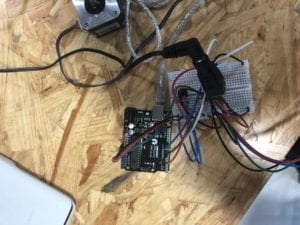
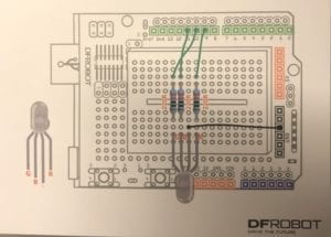
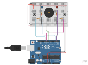
By using the base setup of circuit one, the goal for circuit two was to control the motor with a potentiometer. In order to do so, I had to insert a potentiometer and run the Motor Knob code provided by Arduino.  I plugged the potentiometer into the upper middle part of the breadboard so that two prongs were on one side of the board and one prong was on the other side. I linked a wire from the back prong of the potentiometer to Analog zero (A0) on the Arduino board. I then linked a wire from the left prong of the potentiometer to ground power in the negative column. I also linked a wire from the right prong of the potentiometer to the positive column of the breadboard to ensure it was connected to 5 V of power. A picture of the setup with a potentiometer can be viewed below.

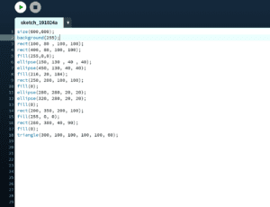
In order to run it properly, I used the code provided in the recitation instructions and copied and pasted Motor Knob into my Arduino browser. After doing so, I changed the steps defined from 100 to 200 and also inputed A0 to account for my analog port that the potentiometer was in. This ensured that I would be able to control the motor by moving the potentiometer. My code for Motor Knob can be viewed under the “My Code” section of my documentation. A video showing the movement of the completed circuit and stepper motor can be viewed below.

Circuit Three:

After laying the ground work by starting the stepper motor and a control for it, it was time to combine it with my partner Sarah and make a drawing machine. To do so, we used two laser cut shorts arms, two laser cut long arms, one laser cut motor holder, two 3D printed motor cut couplings, and five paper fasteners. We fastened both of our stepper motors into the cut out moldings to create stability for the other parts. We then both placed the 3D printed motor coupling on top of our stepper motor in order to create a base to use the short and long arms. We then each placed a laser cut long arm from our motor diagonally out so that they would cross.

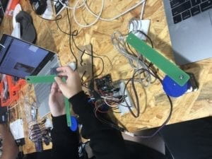
After, we placed fasteners from the long arms into the motor and fasteners from one long arm to the other. My partner and I then placed the short arms onto the ends of the long arms. They were positioned so that the ends of the short arms were criss-crossing. We then put fasteners into the intersection to stabilize the arms together. After,  we inserted the pen into the hole at the end of each short arm. Following this, my partner and I positioned a piece of paper on top of my Arduino kit box to meet the pen. In order to activate the motors again, we used the same code Motor Knob from Arduino. Except below “void loop” we added Map and the corresponding values to link with potentiometer and motor. A full list of the code can be found in “My Code” at the bottom of my documentation. A video showcasing our joint stepper motor drawing machine can be viewed below.

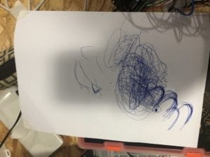
A picture of our finished artwork can be viewed below. We have decided to name it “The blue hills of Shanghai with a storm approaching.”

My Code:

Circuit one code:

/*

 Stepper Motor Control – one revolution

 This program drives a unipolar or bipolar stepper motor.

 The motor is attached to digital pins 8 – 11 of the Arduino.

 The motor should revolve one revolution in one direction, then

 one revolution in the other direction.

 Created 11 Mar. 2007

 Modified 30 Nov. 2009

 by Tom Igoe

 */

#include <Stepper.h>

const int stepsPerRevolution = 200;  // change this to fit the number of steps per revolution

// for your motor

// initialize the stepper library on pins 8 through 11:

Stepper myStepper(stepsPerRevolution, 8, 9, 10, 11);

void setup() {

  // set the speed at 60 rpm:

  myStepper.setSpeed(60);

  // initialize the serial port:

  Serial.begin(9600);

}

void loop() {

  // step one revolution  in one direction:

  Serial.println(“clockwise”);

  myStepper.step(stepsPerRevolution);

  delay(500);

  // step one revolution in the other direction:

  Serial.println(“counterclockwise”);

  myStepper.step(-stepsPerRevolution);

  delay(500);

}

Circuit two code:

/*

 * MotorKnob

 *

 * A stepper motor follows the turns of a potentiometer

 * (or other sensor) on analog input 0.

 *

 * http://www.arduino.cc/en/Reference/Stepper

 * This example code is in the public domain.

 */

#include <Stepper.h>

// change this to the number of steps on your motor

#define STEPS 100

// create an instance of the stepper class, specifying

// the number of steps of the motor and the pins it’s

// attached to

Stepper stepper(STEPS, 8, 9, 10, 11);

// the previous reading from the analog input

int previous = 0;

void setup() {

  // set the speed of the motor to 30 RPMs

  stepper.setSpeed(30);

}

void loop() {

  // get the sensor value

  int val = analogRead(A0);

  // move a number of steps equal to the change in the

  // sensor reading

 ;stepper.step(val – previous);

  // remember the previous value of the sensor

  previous = val;

}

Circuit Three Code:

/*

 * MotorKnob

 *

 * A stepper motor follows the turns of a potentiometer

 * (or other sensor) on analog input 0.

 *

 * http://www.arduino.cc/en/Reference/Stepper

 * This example code is in the public domain.

 */

#include <Stepper.h>

// change this to the number of steps on your motor

#define STEPS 200

// create an instance of the stepper class, specifying

// the number of steps of the motor and the pins it’s

// attached to

Stepper stepper(STEPS, 8, 9, 10, 11);

// the previous reading from the analog input

int previous = 0;

void setup() {

  // set the speed of the motor to 30 RPMs

  stepper.setSpeed(30);

}

void loop() {

  // get the sensor value

  int val = analogRead(A0);

   val = map(val, 0, 1023, 0, 200) 

  // move a number of steps equal to the change in the

  // sensor reading

 ;stepper.step(val – previous);

  // remember the previous value of the sensor

  previous = val;

}

Question One:
What kind of machines would you be interested in building? Add a reflection about the use of actuators, the digital manipulation of art, and the creative process to your blog post. 

I think similar to this recitation, I would also be interested in making a machine that has to do with art. In the past year, I’ve been exposed to so much digital and interactive art that is has made me want to get involved. Although I still respect traditional artists such as Monet, interactive art has become so prevalent in our everyday lifestyle. Just yesterday, I was at the century avenue metro stop and I noticed four stationary bikes lined up in a row. I walked over and heard music also coming from the bikes. After watching, I realized that the power of the stationary pedaling provided different parts of the song. One bike provided the voice, while the other provided the beat. I think actuators are interesting because of their applicability in a project. By being the “middle man” that harnesses energy or a signal and then creates a movement, it works two jobs. The actuator is a focal point which the project hinges on for a dual purpose. I think the creative process can be extremely difficult in many ways. After examining many cases of digital manipulation, I was intimidated so say the least. Digital manipulation looks so incredibly difficult at times due to the copious amounts of resources used. But in reality, it may just come down to a singular sensor. So, I’ve encouraged myself to think big and build after rather than try and think through what would be easiest to build. This ensures that I have and continue to have creative control over my project.

Question Two:
Choose an art installation mentioned in the reading ART + Science NOW, Stephen Wilson (Kinetics chapter). Post your thoughts about it and make a comparison with the work you did during this recitation. How do you think that the artist selected those specific actuators for his project? 

I have chosen to examine waves, by Daniel Palacios Jimenez (Stephen Wilson 117). I think this project is interesting in a multitude of ways but first and foremost because of how it incorporates audience movement. When there is a lot of movement, the rope moves at its quickest, producing movement and sound as a result. But when there is no movement, the rope parallels the silence by keeping still. It isn’t quite within the same realm as my own project, but I can compare the actuator to my potentiometer. In Waves, the rope moves and produces sound thanks to the actuator sensing movement from the audience. In my recitation, I a-liken the sound produced from the waves rope to the drawing produced by my drawing machine. Both the drawing and music have three step process’ where there is a movement (me moving the potentiometer or people moving in front of the rope), a translation by the actuator or Arduino, and finally a result of either music or a drawing.

Works Cited

https://wp.nyu.edu/shanghai-ima-interaction-lab/category/recitations/
(IMA Department Recitation Instructions)

https://www.arduino.cc/en/Tutorial/StepperOneRevolution
(Stepper One Revolution code)

https://www.arduino.cc/en/Tutorial/MotorKnob
(Motor Knob code)

https://drive.google.com/file/d/1MH0D7mTve4KQVn9FJ0KqXWa2TgGuJkPR/view
(Waves, by Daniel Palacio Jimenez)

Group Project Self Reflection, Alexander Cleveland

Alexander Cleveland

Oct 10 2019

Professor Marcela Godoy

Self Reflection Project One

In this project, my group and I defined interaction as a continuous conversation between two or more corresponding elements. We came to this definition by looking at a series of projects that included a fire wall and a click canvas. In the fire wall, by Mike Allison, subjects interacted with the moving spandex wall by touching it, pushing it, and pulling it. By touching it, the person would then alter the movement of the webbed surface on and around the spot being contorted. I thought about how the hand was constantly interacting with the wall as it moved from side to side. Whenever the hand moved, the wall responded in immediate fashion. My group and I found the basis of our definition of a “continuous conversation” within Mike Allison’s project.  The hand represented one element and the wall represented the other element in the conversation. What makes this interaction continuous as we define in our own definition is the constant rate of change along the wall as it is being touched. The wall is unique to each touch and continues to function whenever it is being touched. Its movement is ever present when interacted with. Also, the wall does continue to move on its own after each hand has been taken off, again making it a continuous interaction. This inspired our own project wherein we have sensors that detect body temperature and adjust the home temperature accordingly. 

When we reviewed the click canvas, my group and I found that it did align with the second part of our definition but didn’t fit the narrative of a continuous interaction. A hand would touch the square and thus turn it a different color. While this may fit the narrative of a conversation between two or more corresponding elements, my group and I felt that it was not a continuous motion. This is because once the wall is clicked, it has fulfilled its interaction by turning a different color. While other scholars such as Chris Crawford choose to define interaction as a “cyclic process in which two actors alternately listen, think, and speak.”, we felt it was important to have a continuous motion involved in the making of our own device (Crawford, 1). The difference between the wall and the click canvas is that the wall continuously moves during the interaction, while the canvas only moves once when it is clicked. In the canvas, there is no continuous element, but only a digital on-off nature to it.

When creating our own definition of interaction, my group and I thought back to Lev Manovich’s The Language of New Media where he uses an example of coded video games to exemplify a controlled interaction between the AI character and the human player. Manovich says that these AI players are free of movement to an extent “But because computer games are highly codified and rule-based, these characters function very effectively; that is, they effectively respond to the few things the user is allowed to ask them to do: run forward, shoot, pick up an object” (Manovich, 33, 34). The AI characters that Manovich refers to respond based on the action of the actual player. By doing so, it makes it a continuous conversation between the two corresponding elements. So as long as the actual player points a gun at and threatens the AI character, the AI character will continuously respond in a multitude of programmed actions. The AI has a mind of its own, but only in response to the player (What is New Media, 34). The balance of read and react between the two parties formed the core conversation part of our definition. In Chris Crawford’s What exactly is interactivity?, he also makes an important point that helped form the continuous part of our definition. Crawford uses a conversation between two people as an example of his cycle wherein he says “This process of conversation cycles back and forth, as an iterative process in which each participant in turn listens, thinks, and speaks” (Crawford, 5). Thus meaning that as long as the two parties are present and speaking, there is a cycle of conversation between them. By using these two sources, my group and I formed the definition of two elements having a conversation  in a continuous manner.

When making the smart home interactive body temperature sensors, my group and I took into account the importance of the continuous interaction aspect as our greatest challenge. We looked at the fire wall and saw how every time a hand was touching it, the wall would respond in various ways. We took this concept and applied it to a multitude of objects used everyday alongside the human body. Rather than a singular wall, we would put sensors on a phone, chair, bed, table, pillow, door handle and many more things to detect body temperature. Before this step, the person would set their own preferences in an acclimatization setup process so the sensors would know how to correctly respond to their body temperature. This fulfilled the second part of our definition by establishing a “conversation between two or more elements.” To fit the narrative of a device in 2119, we wanted the subject to have as little work to do as possible. We didn’t want the interaction to stop at a sensor just responding once as the subject sits down. Because if a subject was quite cold initially and the sensor made the room abnormally hot as a response, eventually the subject would become accustomed and possibly become too hot. In order to avoid this problem, we created a continuous relationship where the sensor is reading the subject’s temperature every minute that they are in contact with the object. As long as the hand was touching the fire wall, it reacted to the movement, and as long as the subject is sitting on the chair, the sensor adjusts accordingly to the preferred temperature. The body and sensors are having a conversation just as the click canvas showcased. But what makes our definition and project different is the continuous nature wherein the sensors and body are constantly adjusting to always have a preferred temperature. 

Sources Used

http://aaron-sherwood.com/works/firewall/

https://create.arduino.cc/projecthub/natthakit-kim-kang/click-canvas-an-interactive-wall-04332c?ref=tag&ref_id=interactive&offset=0

https://drive.google.com/file/d/1wBoiakCPAAQhGQzb0sNNVmOyWDphRXj2/view

http://s3-ap-southeast-1.amazonaws.com/ima-wp/wp-content/uploads/sites/3/2017/08/05164121/The-Art-of-Interactive-Design-brief.pdf

Recitation Three, Joystick Module, by Alexander Cleveland

Introduction

My partner and I chose to use the joystick model for the third recitation session. We both found it intriguing to control a joystick and have different values correspond with different directions as a result. Our goals for this project were to first correctly set up the joystick module, and also to incorporate it into the three colored LED light which could display red, green, and blue. We wanted to push ourselves into unknown territory with an unfamiliar device at hand. We both felt it would add to our confidence and problem solving skills within the physical set up and code. The initial circuit to test the values of the joystick was relatively simple to set up with only four wires. After testing it out and writing down the X and Y values associated with the different movements, we moved on to the larger task at hand of connecting it to the LED. 

Circuit One, Joystick Module Initial Setup

Although the diagram called for five different connections from the joystick module to the Arduino, we only ended up needing four because my partner and I declined to use the key (digital) option and stick entirely with analog throughout the process. After gathering the necessary resources of four jumper wires, an Arduino board, a USB A to B cable, and a joystick module, we were ready to begin. Pictured below is the diagram we used for guidance throughout the circuit building. All credit to Brainy Bits for the image.

As I previously mentioned, the yellow wire at the top of the diagram was not used in our trials because my partner and I decided to only used analog function with the joy stick. My partner and I used the first jumper cable to connect the X value from the joystick to A0 under analog. We then used a second jumper cable to match that action but instead connected it from the Y value of the joystick to the A1 value under analog. This ensured that the joystick would be able to interact with the inputted code once connected with my partner’s laptop. After doing so, my partner and I connected a jumper cable between the ground power on the joystick to the ground power on the Arduino board. This was just to ensure that the ground power from the Arduino board was flowing into the right input. We then used the fourth (and last) jumper wire to connect the VCC on the joystick into the 5 volts (5V) in the Arduino board. This action completed the wiring portion as we moved onto setting up the code. Below is my own schematic for the joystick module.

The code was under the jurisdiction of digitalWrite because we limited ourselves to only those pin numbers for simplicity purposes. After entering the corresponding pin numbers (A0 and A1) my partner and I uploaded the code and connected the USB A to B cord with the Arduino board. As a result, we were able to see which X and Y values correlated with certain movements of the joystick. The values were as follows:

  X Y
Left 0-200 519
Right 900-1023 519
Up 524 900-1023
Down 524 0-200

A video of the completed circuit can also be viewed here (IMG_2611)

A picture of the completed circuit can also be viewed below.

Circuit Two, Incorporating an LED Light

After setting up the initial circuit with plenty of time remaining, my partner and I decided it would be a fair challenge to set up the RGB LED light in correspondence with three 220 ohm resistors and four jumper cables. The goal of this project was to link the joystick module with the RGB LED light so that a distinct directional movement would dictate the color of the LED.
Below is the schematic we used a reference. This schematic was provided by DFROBOT which was found within the Arduino kit we used.

In the initial stage, we plugged in the RGB LED light to the middle of our breadboard. We then used three different 220 ohm resistors to correlate on the same row as prongs G, B, and R. On the other ends of the resistors, we used three jumper cables to connect it into the digital pins of 9, 10, and 11. On the remaining prong of the RGB light, we used a separate jumper cable to source it back to the ground power of the Arduino board. In order to correctly connect the joystick module, we left the original wires from that circuit plugged into the Arduino. In order to tether the interaction between the LED and the joystick, we used two jumper cables and connected one for the positive column of the breadboard to 5V, and one from the negative to the ground power of the Arduino board. After checking the specs on the physical end, my partner and I entered the code with help from Brainy-bits.com and its tutorial on the joystick module. Once complete, my partner and I plugged the USB cable back into the Arduino and uploaded the code. In the first effort, the circuit faulted because my partner and I not noticed that we plugged the LED light in incorrectly. Therefore the wires weren’t corresponding with the correct prongs of the LED, which also led to a fault in our code. As a result, we switched the wires to match accordingly with our code for simplicity. The circuit worked on the second try. A picture of the completed circuit can be viewed below. This picture is depicting the color change when the joystick is moved to the left.

My own schematic for circuit two can also be viewed below.

Conclusion

I enjoyed undertaking the challenge to complete this circuit due to its intricate coding techniques and subtle hardware adjustments along the way. I think it was good for us to use the first circuit as a building block to then incorporate the joystick module later on in tandem with the LED. It gave my partner and I the confidence to deal with an activity we had never done before. Although the second circuit took us two tries, I valued the experience of learning from my mistakes. It was a good lesson that no matter how simple a circuit may look, it can be extremely difficult to physically build. My partner and I underestimated the physicality of this project from the start. It will benefit us later on because it has taught us to approach every project from the same attitude. Although we took the confidence from building the first circuit into the joystick module, we turned that into arrogance and became careless as a result. I am glad we picked the joystick because it was an out of the box project for my partner and I. Having never dealt with a module such as this one, it exposed us to the intricacies that are required to maintain a complex project. By balancing the code along with the physical wiring, I learned more than I could’ve if I had picked a circuit I was comfortable. It should also be noted that I introduced a strategy I had learned from Recitation #2 wherein I became unorganized throughout the wiring process. I created a checklist of all materials used, so it actually helped when eliminating possible malfunctions when the circuit was not originally working.

Questions

  1. My partner and I intended to assemble an RGB LED light to be controlled by the joystick module. When we would move the joystick to the left, the RGB LED light would coordinate and change colors. This would go on for the three different values possible within the light. A possible real life use for this joystick could be in a traffic light. While it obviously wouldn’t be used everyday since there are automatic sensors for traffic lights, it could be used in emergencies when the light isn’t working properly. If the traffic light were to need manual attention for the intervals of green-yellow-red, this joystick could be used for such an occasion.
  2. I think it code is compared to a recipe due to its invariability. By this I mean that in order for the code to correlate with the circuit, the letters need to be capitalized a certain way, the pin number has to be exact. The reason recipes exist is because someone else has found the exact number of ingredients and their amounts needed to make the end result taste good. To bake a cake, you need butter, eggs, flour, baking soda, and sugar all baked at a certain temperature. In the end, you get a cake made to the specifications that the majority of people have deemed acceptable over time. The same can be said for coding and wiring an Arduino circuit. If one forgets the baking soda (the pin #) the code will be invalid and the entire project will cease to work correctly. Both a recipe and coding need to be followed exactly in order correctly conduct them.
  3. I think in my generation especially, computers have affected our behavior in a multitude of ways. I think the most evident is social interactivity. From what I’ve witnessed, a lot of kids have trouble interacting with one another. Not that teenage awkwardness doesn’t still exist, but computers have amplified this behavior through online chatrooms. It’s smuch easier to direct message someone online and have time to think hard and respond. A common example could be in a tense situation wherein both teenagers act like chess pieces, with each one plotting their next move. Having a computer between two voices amplifies the intensity within the conversation. There is less flow and more thinking involved whereas in real life it is based on read and react behavior. When I have a conversation with another human being, I depend on my skills to read someone. So, it’s more based on improvising than having time to think. So in a way, I think computers have my generation more reclusive and less willing to interact for fear of social anxiety. 

Sources Used

https://www.brainy-bits.com/arduino-joystick-tutorial/

https://www.dfrobot.com/ (DFROBOT used for reference in Circuit Two)

https://wp.nyu.edu/shanghai-ima-interaction-lab/category/recitations/

Recitation Two, Arduino Basics, by Alexander Cleveland

Introduction

In the second recitation of the term, my partner and I worked on three different circuits involving the Arduino and breadboard components. The goal of circuit one was to create a fade with the given LED light on the breadboard. The goal in circuit two was to create a tone melody, which in simplest form is a short song produced by the speaker on the board. Both circuits were simple with only a few wires involved so they took a relatively short amount of time compared to circuit three. The goal behind circuit three was to use the arcade buttons we picked up at the front and input them into the breadboard to create a game where the first person to ten clicks using the button was the winner. This involved many more wires and also delicate treatment of the wires because there were many bunched together. My individual goals were safety (once again) and also getting the circuit right on the first try. I do value trial and error as it helps me learn more about the process, but at this stage in the class I am beginning to learn more so I also begin to expect more out of myself. Safety is and always will be my first priority when entering these types of projects. As I am still somewhat unfamiliar as to how different wires could react with one another, I make sure to keep the Arduino board unplugged from the computer while moving wires and other pieces around. This ensures that nothing will unexpectedly spark and hurt me or my partner. All resources used for this project were borrowed from the IMA lab in room 826/825 at NYU in Shanghai and also from my own Arduino kit handed out at the beginning of class. The materials used for this recitation are as follows:

From Arduino Kit:

1 * Arduino Uno
1 * USB A to B cable
1 * breadboard
1 * buzzer
2 * LEDs
2 * 220 ohm resistors
2 * 10K ohm resistors
2 * pushbuttons
A handful of jumper cables

From cart:

2 * arcade buttons
1 * Multimeter (optional)

(Material list is sourced from NYU Shanghai Interaction lab syllabus)

Circuit One, Fade

My partner and I started circuit one by reviewing the diagram and collecting the necessary materials needed. This included an Arduino board, a breadboard, an LED light, multiple jumper wires, and one 220 ohm resistor.  The original diagram from the recitation post can be pictured below. 

We started by hooking up the breadboard to the power and voltage of the Arduino circuit. This meant connecting a wire from the negative column to the ground power and also a wire from the positive column to the 5 Volts. This gave way for us to insert the resistor and LED light onto the main spread of the breadboard. One end of the resistor was in line with the LED and the other end was connected to a green wire. This green wire (a5) was also connected to pin ~9 on the Arduino board to ensure our ability to manipulate the power through coding. A picture of our initial set up can be seen below.

As is pictured above, there is also a grey wire (USB A to B cable) which sources power from the laptop to the Arduino board. It acts as a power tether to connect the computer to the Arduino to the breadboard. It should also be noted that we rejected the optional use of a multimeter for this circuit. In order to access the code we opened Arduino and clicked on examples and then fade. Once we entered the correct pin number (~9) and used digital write to correlate with it, we decided the circuit was adequately set up and plugged the USB cord into the computer to transfer the code. A complete video for circuit one can be seen using the following link (IMG_2568). It should also be noted that my partner and I achieved the correct format on the first try of building circuit one (one of my goals).

Circuit Two, Tone Melody

Circuit two took an even simpler form than circuit one by downgrading from three wires used to just two.  The objective of circuit two was to create a melody by using a speaker connected to the Arduino board. A diagram provided by the recitation blog can be found below. For this circuit, my partner and I used an Arduino board, a breadboard, a speaker, and two jumper wires. 

We started by unplugging the USB cable from the computer to ensure maximum safety while adjusting wires and other parts. Following this, my partner plugged in the speaker to the breadboard and I used a wire to connect it from the ground power on the digital side to one leg of the speaker. This ensured that the speaker had proper electricity from the Arduino to make a sound. My partner then plugged a second wire from the other end of the speaker into Digital pin number 8. A picture of the completed set up can be seen below.

After completing the physical set up, my partner and I entered the corresponding code by using examples from digital to toneMelody. After examining the code, we inputed the values of different tones and notes listed on the Arduino tutorial into a new tab as instructed. After doing so, I plugged in the USB cable to the computer and uploaded the code appropriately. A video of the completed circuit and corresponding song can be found here (IMG_2569). It should be noted that we completed this circuit successfully on the first try again.

Circuit Three, Speed Game

The goal of circuit three was to create a two player game wherein each player presses a button as fast as they can and whoever reaches ten clicks first is the winner. In order to understand the physical design and code, we first had to use Tinkercad’s online resource as a guide. A diagram of the circuit from their website is pictured below. (All credit reserved to Tinkercad online)

Considering the amount of wires my partner and I were dealing with, we decided it would be best if one person were to handle the wires since it would be difficult to split it up and keep track of the other’s progress. So I was tasked with handling the wires and immediately got to work. I started with the two simplest wires, a red wire which stemmed from one positive column to the opposite side positive column. The same was done for the black wire as it went from negative to negative column. After this step, I plugged a black wire from the negative column on the other end of the board to the ground power on the Arduino board. I correspondingly inserted a red wire from the positive column on the same side to the 5V of power on the Arduino board. These two wires now ensured that the breadboard would have power once we plugged the USB wire into the computer. In order to simplify matters, I then plugged the speaker into the middle of the breadboard, flanked on both sides by a 220 ohm resistor which stretched over the middle median of the board so each resistor was connected by both sides. I also plugged in both LEDs so that one leg of each LED light was lined up in the same row as a 220 ohm resistor. These base foundations for the setup gave me better reference to plug other wires in appropriately. I followed this by plugging in a wire from Digital pin 2 to the other free LED leg on the right side of the board. I made a similar move right after this and plugged a wire in from digital pin 3 to the free leg of the other LED light on the left side of the bread board. This ensured symmetry so far within the set up of the board. After, I set up a wire from the left leg of the speaker to Digital pin 8 and another wire from the adjacent leg of the speaker to the negative column of the breadboard. I then set up two 10k resistors on the lower side of the board facing perpendicular to the 220 ohm resistors (although not in the same row). Symmetrical wires were then placed from each end of each the 10K ohm resistors to digital pin numbers 10 and 11 respectively. The other end of the 10k ohm resistors both had parallel wires running to the upper negative columns of the board. We both plugged in a button on opposite side of the board wherein a leg would line up with a row connected to either pin 11 or pin 10 through the 10k resistors. And what I thought was the final step was connecting two parallel wires from the negative columns on the lower side of the breadboard to the same row as each 220 ohm resistor. After completing the corresponding code, it was time to plug in the USB cord and give it a try. To no avail, the game did not work the first time and we solicited the help of teaching assistant Eszter to help figure out the problem with our circuit. 

After a short period of deliberation, we noticed that the circuit was missing two vital wires at the top of the breadboard. Each wire connected each button to the positive column on the board. So, without the connected wires, the buttons had no voltage being sourced back from the Arduino board. Once we fixed the mistake and plugged in the USB wire again, I hit the Arduino board reset button and re-ran the code. This time it worked; a video of the functioning game can be viewed here (IMG_2634.TRIM). Following the completion of the game, a celebratory tune was played by speaker and one of the LED lights lit up to signal victory. Also, below is my own visual schematic for circuit three.

My Reflection

Aside from the minor wiring error in circuit three, I completed my goal of successfully creating circuits without a hitch in the process. I will take 2/3 initial success’ as a positive and use that confidence moving forward. I also achieved my second goal of safety throughout the entire three circuit process. This was especially difficult to ensure in the building of circuit three with many wires, but my partner and I held each other to accountable levels of safety throughout. Something I learned from building circuit three was how to accordingly keep track of every wire and instrument placed onto the breadboard. Because all wires are different colors from that of the original diagram, it was difficult to keep track of so many, especially when they began to get clustered as more were inputed. So after the fact, I recognized that I need to create a checklist of all the required materials and check them off as I input them into the circuit. This will help in the future with organizational flow. I also learned from my mistakes last time and was more willing to ask for help this time which ended up aiding us to complete the third circuit on time.

Questions

  1. I define interaction as an inputed value with a corresponding output value. For example, when I swipe my metro card to enter an electronic gate, the gate opens as a result of my swiping my card. There was the input of the swipe, and the response was the gate opening. Examples are everywhere throughout our life without even realizing it. When I ask siri the weather, it responds and tells me it will be sunny in Shanghai today. My input of asking siri was met with an output response of siri telling me the weater. At its simplest form, interaction is output caused or triggered by an input. A similar example is when my partner and I Inputed a code for the correct pin number in the fade circuit, and the output was the corresponding fade of an LED. Thus, the LED faded, because we inputed code to do so. Where this gets interesting is when Igoe and O’Sullivan begin to introduce the concept of interaction. In their book Introduction to Physical Computing they quote a separate author, Chris Crawford, saying that interaction is defined as “an iterative process of listening, thinking or speaking between two or more actors.” (Intro to Physical Computing, Introduction XX). Although I agree with the principle of the definition, I want to disagree with the notion that an interaction is limited to these three actions. I think interaction carries a far broader set of categories which is why my own definition is a broad one itself. I did this on purpose to encompass much of what the world defines as interaction. However, Crawford is right to point out that interaction is between two OR more actors. I think this point is especially important to conveying the message that interaction isn’t just limited between two people. It can also be a chain of interaction stemming from machine to machine or person to person.
  2. The 10K resistor was used in coordination with the button to manage the amount of voltage available to it. Without a resistor, an unprescribed amount of power would be at the disposal of the button which would likely cause it to malfunction or overheat. The resistor simply acts as a buffer between the button and the power source of ground power to adjust the power to an appropriate amount.
  3. I would rearrange the LED lights in green and red to spell out the Chinese characters 欢迎来我的家 which directly translates to “welcome to my home” and place these on the front wall of my house. Likely during the holiday season to spread the cheer!

Sources Used

https://www.tinkercad.com/things/6MzvN5rlZlr-race-the-led-interaction-lab-ima

https://drive.google.com/file/d/1uviCK0V71cQpA76PV9PK03Df14vcsd0y/view (Igoe and O’Sullivan, Introduction to Physical Computing, introduction)

https://wp.nyu.edu/shanghai-ima-interaction-lab/category/recitations/