Pirate Chase! – Audrey Samuel – Professor Rodolfo

Initially, I saw interaction to be the ways in which humans communicate with electronic objects and how these objects react to our communication, creating a two way effect. The chapter on Interactivity under the Art of Interactivity by Crawford refers to interaction as a cyclic process between two  participants and Crawford compares interaction to a conversation between two people. I therefore stressed on using the word communication because to me interaction required multiple electronic inputs and outputs going back and forth. However, after conducting more research for my midterm project my definition of interaction slightly altered whereby it became not only a form of communication but also a way of blending technology and human abilities together in the most natural way, without undervaluing the capabilities of humans. One of the projects I had found online was the Mario Mushroom Block, inspired by the Mario game and designed by Scott Clandinin. The user would have to hit the bottom of the box, causing a sensor to open up the top of the box resulting in a mushroom popping out (hackster.io). We wanted to make a game similar to this but with prolonged physical interaction and technological interaction. 

Mario Mushroom Block (Hackster.io)

For our midterm, my partner Jackson and I came up with the game Pirate Chase which was a boat racing game where two participants battle with each other by blowing on the sails of their boats across the water to reach the finish line.  In Chapter 13 of Art of Interactivity, Crawford gives specific advice on how to integrate interactivity when designing Games. We had to keep in mind hand-eye coordination because we wanted our game to “demand fast reflexes”, except instead of using their hands, our users would be physically engaged by manually blowing their boats. The technology we used here was the infrared sensor on the Arduino board which would detect when their boats had reached the finish line and light up to indicate the winner. By merging both technology and human skill we were able to create an interactive project that could be played at a carnival or funfair to test users’ competitive skills and allow them to have fun!

We first drafted out how we wanted to construct the objects used in the game such as the boats, sails, etc. and how we would incorporate the sensors, light and sound. We began by 3D Printing our boats without sails. We wanted to make the sails ourselves and find suitable material that would be waterproof but would also move the boats when blown upon. Paper did not work because it would get wet and cardboard was too heavy, occasionally weighing the boat down. We then decided to use a light, plastic bag which worked out perfectly. We then had to think about how we could make our game interactive and fun. Our original idea was to have both participants standing next to each other on one end of the water and the first to blow their boat to the other end would be the winner, but we changed this to make the participants stand across from each other instead so that they were both able to look at each other while playing. Games of today are very electronic oriented with people rarely looking at each other when playing and so we thought we would change this with our game to make it more physically interactive. When designing the game, we had originally wanted to fix fans using a DC Motor so that the users would press a button, activating the fan which would then blow the boat. Later we realized this went against our definition of interactivity because it felt as though the game was being played more by electronics and less by the users. After much consultation, we decided to remove the fan and planned on using straws to blow on the boats allowing users to utilize their physical skills.

After we had 3D Printed our boats and made the sails we tested them to see if they would float. To our relief they floated but this was short-lived because after we hot glued the sails to the boats they began to weigh down on one side and sink when placed in water. Our infrared sensor worked but we struggled with altering the code to get the LED light to turn on when the object was close to the sensor. After a while we realized we hadn’t properly defined the LED light and we were able to rewrite the code to make it work. We decorated our plastic box which was our “tank” and made boxes to cover our Arduinos and breadboards. With the pirate theme in mind we decided to color the water in the tank blue, and to turn our boxes into treasure chests. 
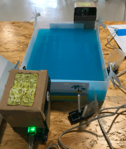
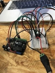
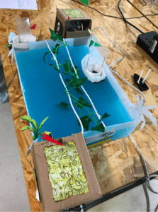
During the user-testing session we received really valuable feedback that helped us improve our project. The boats kept sinking when blown and people did not like using the straws to blow the boats. In addition to this the boats kept crossing lanes and someone suggested fixing a barricade in the center. There was also no proper indication of when the game should start to which someone suggested including sound, or a flag attached to a motor that would wave to alert the start of the game. To improve our project we 3D printed hollower boats which were more sturdy and did not sink. We also fixed a barricade in the middle and instead of using straws to blow the boats we asked our users to blow them manually. To indicate when the game was to start we attached a buzzer and a button and hoped to play a Pirates of Carribean song to indicate the start of the game after the button was pressed. We were unable to get the song to play in the code so we used a simple tone instead.
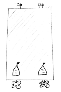
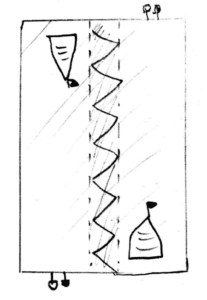
                                    

Sketch 1 : Before user-testing         Sketch 2: Updated after user-testing 

The Pirate Chase Project was an interactive game we designed to encourage the use of both technological and human abilities in unison. We wanted to blend technology and human abilities together in the most natural way and we hoped that by blowing on the boats and using an infrared sensor and turning on the LED we would be incorporating both technological and human factors together to create an interactive project. Our audience might not have sensed this at first as our tank was too small and did not give enough space for them to truly play the game. However, as I spoke to more people during the user testing session they appreciated the idea of the game, and loved that they could be looking at their competitor while blowing their boats to victory. If I were given more time I would try and improve the tank by getting a bigger one, fixing in an obstacle course with servo motors and including more participants to make it much more interactive. After this project I began to understand the essence of Interactive Media Arts and how it should be about making our lives better without entirely taking away our skills or doing our jobs. In the Field Guide to Human Centered Design published by Design Kit we are shown the ways in which research must be done, first based on basic interactions with individuals. One must conduct interviews, watch people interact with certain objects in different spaces and do secondary research as well before they can begin to put things down on paper, reminding us again that before we look at anything technological we must go back to understanding the needs of the human first. Most times we are told that the drawbacks of Artificial Intelligence and Robots are that they take away our jobs and are more efficient or faster, but at the end of the day nothing can beat the human mind (at least not yet!). This project was a reminder that getting people to use their skills by choosing whether to blow on their boats or their opponents’, and also having technology to provide sounds and lights, shows how technology and Humans can co-exist. 
 

Resources:

Recitation 4: Drawing Machines – Audrey Samuel

During our fourth recitation, we were tasked to create a drawing machine by using an H-Bridge and a stepper motor. I worked with Tian Tian and we successfully created our drawing machine (however, getting it to draw exactly what we wanted was the real task). 

For the first step we were required to assemble the circuit and make sure we placed the H-Bridge/IC correctly unto the breadboard. We had to look for the semicircle on the H-Bridge to know where the front part was and using the diagram we were able to map the pins correctly. We then began to assemble the circuit and made sure we color coordinated the jumper cables to make it easier for us to assemble. We had trouble at first connecting some of the pins to ground since there were only two ports on the arduino for ground, but we later learnt that we could connect ground on the arduino to ground on the breadboard and then connect it to the IC using jumper cables. We were successfully able to assemble our circuit and appload the stepping revolution code. We both made our circuits individually but we assembled each component together so we could help each other. When we uploaded the code, our motor turned one revolution. 

For the next task, we were required to upload the motorknob code also found under the examples within Arduino. We had to change the number of steps here to 200 as well as use the map() function in order to control the direction in which the motor moves by using the potentiometer. We correctly placed the potentiometer on the breadboard and now had to make sure we entered the map() function properly by placing both the highest and lowest values. 

map(val, 0, 1023, 0, 200) 

Finally in step 3 we were required to make a mechanical arm that could hold a pen on paper. Tian Tian and I put both are circuits together for this step. We were able to make the machine by looking at the diagram and getting some help from the learning assistants and Professors as well. We then plugged our arduino into 12 VDC power. We were reminded at the start of recitation to make sure we plugged in our components properly to avoid breaking our computer. Our drawing machine worked! The arms kept falling off because we did not properly fasten them with the paper clips but once we did we were able to use our potentiometer to control which direction we wanted the motor to rotate towards.

Video of Drawing Machine working

Question 1:

From recitation four and the lectures we had this week, I learnt that a lot of devices we use in our day to day lives have at least a DC motor or Servo motor built in them, these include electronic devices such as phones and other electronic appliances such as blenders and fans. Actuators within these devices help move and control the rotation of the blades for instance in a blender or fan. The drawing machine we built in class made me think of a heart rate monitor whereby the machine would draw a line up or down showing spikes in one’s heart rate. Other machines that I would be interested in building could be a machine that would make the life of an architect much more easier by perhaps mapping out their ideas in 3D and using a motor to move to move a pen along a piece of paper to map out these architects ideas. It could help them sketch out their drawings more accurately and also watch these drawings come to life instead of sitting in front of a computer and watching the computer do the drawings for them.

Question 2: 

Art + Science NOW by Stephen Wilson features a number of really groundbreaking robotic and kinetic projects, mixing reality with the virtual world. One project I saw to be really interesting was the Feral Robot Dog by Natalie Jeremijenko. The little robot is able to detect environmental problems through pollution sensors attached to it. What makes it more unique is that when the robot senses these problems, it either barks or jumps up and down as though it was an actual dog. By playing with robotic toys, Natalie aims on encouraging the public to be more aware of environmental problems. Although this might be a very light hearted manner to gain the interest of the public, it still does the job and encourages people to be more mindful of their surroundings and protect the earth.  Natalie most likely used sensors that detect certain chemicals within the atmosphere or other pollution sensors that show when the air quality within a certain area is not normal thereby implying that it is polluted. The project we made in class is quite different as it had no sensors to detect temperature changes etc. but there can be some similarities as both the drawing machine we made and the Dog Robot are machines or robots that move because of motors attached to them.

Group Research Project Final Blog Post – Audrey Samuel

Interaction in my opinion would be the ways in which humans communicate with certain electronic objects and the ways in which these objects react to our communication, creating a two way effect. In the article Art of Interactive Design, the author likens interactivity to a conversation which was why I chose to use the word ‘communicate’ in my definition. In a conversation between two people, one participant has to listen, think and then speak or respond depending on what the other participant has just said. With interactive projects that have been built using Arduino etc., the input such as electricity becomes the “listening process” and the output such as the LED lighting up or sound coming from the buzzer becomes the “speaking” process linking back to the whole idea of interactivity being a conversation. 

When researching on interaction, two projects I found really interesting were the Interactive Mario Mushroom Block Project and Augmented Reality in Education Project (all found on hackster.io). In the first project, the creator got his inspiration from the blocks in Mario whereby you would hit a block and a mushroom would pop out. He created a 3D version of this using Arduino 101, servo motors and a block tin. The individual would interact with the block by hitting it on the bottom, the block would then sense that it has been hit and open up, shooting a mushroom out. Here, interaction was quite limited in my opinion as there was only one input and one output. It was only detecting if the block had been hit or not and then popping out the mushroom without really creating a conversation. 

The second project I looked at seemed to fit in better with my view of interaction as there were more inputs and outputs creating more of a back and forth conversation. The purpose of this project was to use augmented reality to bring life to objects in a museum for educational purposes. Children would therefore be able to interact with the objects in the museum and bring them to life by browsing a printed ‘book’ in front of a screen. Children would be able to refer to this book and choose how huge they wanted the object to be or what details they wanted projected in front of them. This would then project the objects in a 3D form for the children to interact with. I found this to be more interactive as there were multiple inputs in the book and multiple outputs as well. 

For our group project, we came up with the idea of the ‘Doglar’ which is an innovative dog collar that helps the dog’s owner communicate better with their dog. The dog collar which would be worn around the dog’s neck would be made of adjustable material and would be able to detect when the dog is dehydrated or hungry. It would then automatically signal the nearby food/water dispenser to provide food or water for the dog. It would also be able to detect the temperature of the dog or if the dog is feeling ill and diagnose the dog. The owner is then better able to understand their dog as they can now see what the dog may be going through with the help of the collar. The collar could also be used to train the dog by providing treats through the dispenser every time the dog does something right such as if it urinates in the correct place and send a vibration every time the dog does something bad. This proposed definition fits in with my definition of interaction as it shows that there are multiple inputs within the collar and outputs as well through the dispenser. The collar becomes the “listening process” as described earlier on and the dispenser can be similarly likened to the “speaking process” indirectly allowing for communication between the dog and its owner. 

References:

  • The Art of Interactive Design 

Recitation 3: Sensors – Audrey Samuel

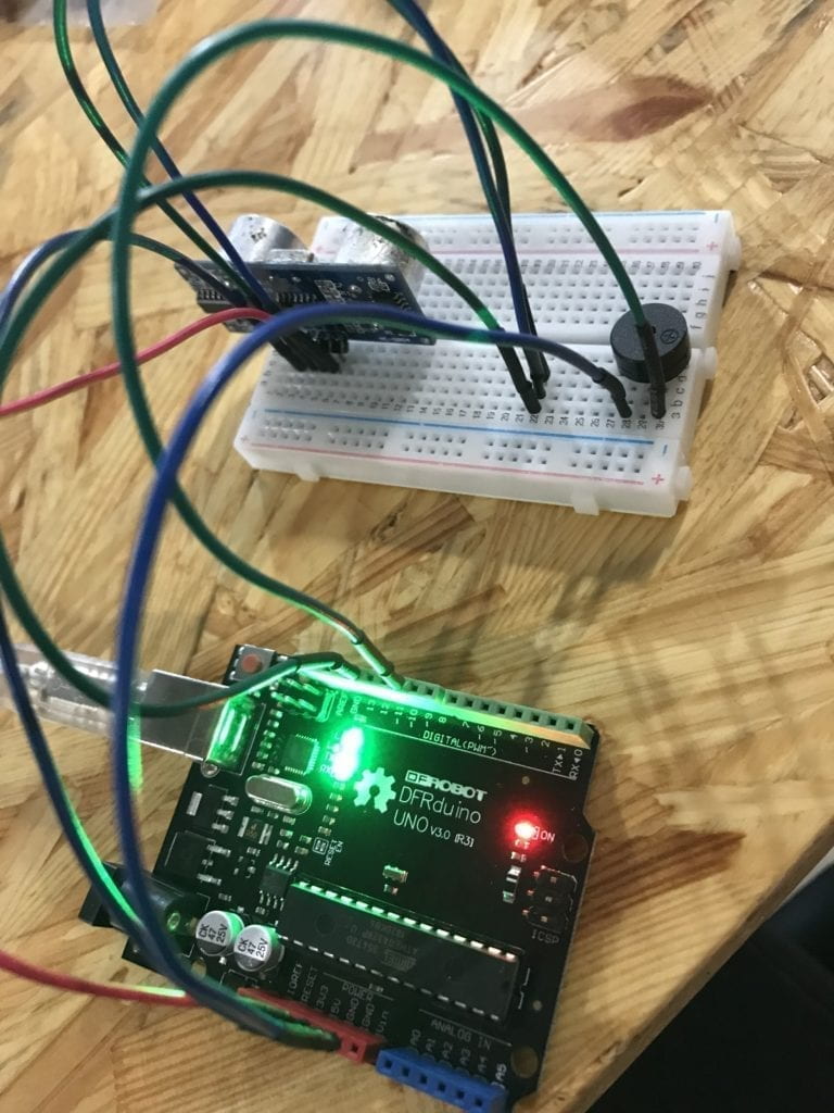
For our third recitation we were asked to choose a sensor and build a circuit that integrated our chosen sensor with our Arduino. We were reminded to refer back to previous lessons and make sure we had to map() an analog input. Tian Tian and I chose the Ultrasonic Ranger which is used to detect distance. We used the Ping example in Arduino to help us and chose a buzzer to be our output. 

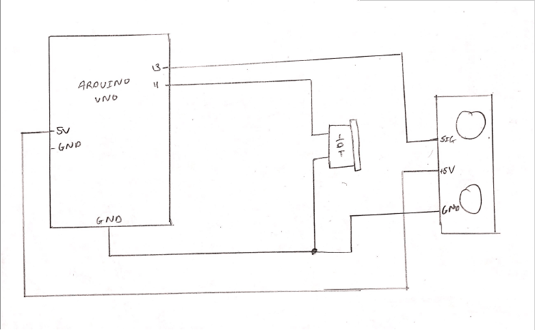
We began by placing the ultrasonic ranger into the breadboard. The ultrasonic ranger had four different prongs which we had to pay close attention to. The first prong was ground and so using jumper cables we pinned it from Ground on the ultrasonic ranger to Ground on the Arduino Uno. The next two prongs were the Trig and Echo pins which we were tasked to place in the same Digital Pin in our Arduino. We were confused as to how we could place both of these into one pin but with the help of the learning assistant we realized that we could use another jumper wire, connect it to a random pin on the breadboard and connect the trig and echo pins to it we could send it to the same digital pin. 

We then placed the buzzer into the breadboard ensuring that the positive side was connected by a jumper wire into digital pin 11 and the negative to Ground. We then uploaded the Ping code which were able to access under the Examples section in Arduino. We made sure we modified the pingpin location to digital Pin 13 as that was where we had connected both the Trig and Echo pin. In order to check if our ultrasonic ranger was working we clicked on the serial monitor and we noticed that it provided various readings of distance depending on how close or how far we placed a random object near it.

We had a few issues however with the connecting the buzzer as a form of output because we did not know the appropriate edits to make to the code. We were unable to make the code work during recitation so I met up with a Learning Assistant later that week and learnt how to rewrite the code properly. I later learned I had to define the “buzzer” and the digital pin I connected it to, as well as use the “If” function. We changed the code to activate the buzzer if the object was less than 37cm from the ultrasonic ranger. With the tone function we were also able to change the frequency of the buzzer. 

if (cm<37) {
tone (buzzer, 1500, 100);
} else if (cm.337) {
noTone(buzzer); 

Schematic for Circuit

Question 1:

We decided we would use a buzzer as our form of output when using the ultrasonic ranger. This reminded me of the beeping sound a car makes when it is reversing or parking as it alerts the driver by beeping loudly when the back of the car is close to a wall etc. We would also use this in museums in front of paintings or artwork to ensure that people do not step too close to the artwork. If they do get closer the buzzer or alarm would go off, alerting security. 

Question 2:

Code can indeed be described as following a recipe or tutorial because it is a step by step process. If we leave one ingredient or one bracket out, the entire code may not work and so in order to make sure our code works properly we have to go through it step by step. In addition to this certain things or procedures must come first before other things as can be seen when coding as the void(setup) function should come first before void(loop). 

Question 3:

Manovich in Language of New Media shows us the effects of the computer on humans and how the identity of media has changed over the years. He refers to Theodore Adorno’s theory of the culture industry whereby demands of the individual controls the market and he illustrates this by using the example of a car. A customer might provide the design of their dream car to a showroom however they do not instantly receive this imagined car after designing it as it still has to go to the factory to be built and then returned back to the showroom to be collected by the customer. On the other hand, with the computer this immediacy with obtaining results is possible as the computer is both the showroom and the factory because data can be sent through wires at the “speed of light”. The ease with which humans now receive information has made us more and more dependant on the computer, making us less willing to find information on our own or learn things without looking it up online. 

Recitation 2: Arduino Basics – Audrey Samuel

In our second recitation we were required to build three separate circuits using our Arduino Board.    I worked with Tian Tian in building the circuits and we were successful with building all three even though we came across a few obstacles along the way. 

Circuit 1: Fade

For the first circuit we were required to use the Fade example on Arduino. The Fade example uses analog output (PWM) to fade an LED. I later learnt that PWM which stands for Pulse Width Modulation is a way to obtain analog results using digital means. By using PWM, the digital pin turns on and off very quickly depending on the ratio thereby creating a fading effect. To begin, we  had to connect our LED to our breadboard with a 220 ohm resistor and ensure that the anode was connected to digital output pin 9 and the cathode connected to ground. We then uploaded the code for the Fade example found under the Arduino site. We experimented with the code by changing the values for the delay function and the fadeAmount. 

Circuit 2 : toneMelody

For circuit 2, we were asked to use the toneMelody example using the piezo buzzer to play a little melody. We connected our speaker to the Arduino Uno but first had a few problems connecting the jumper wires properly as we kept inserting it to the sides of the buzzer instead of right in front of it (horizontally) as seen below to the left. We later learnt that this would not allow electricity to flow in order to activate the buzzer and changed the jumper wires to the correct position as seen below to the right. 


We then uploaded the toneMelody code found in Arduino. The new thing we learnt here was that this specific code would require an extra file to be used which was the pitches.h file which would differentiate between the various music notes. We inserted this file by clicking on new tab and pasting in the pitches.h code found in the example under the Arduino website. The buzzer worked and played the melody we had uploaded!

Circuit 3: Speed Game

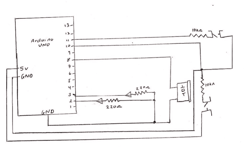
The third circuit we built was by far the most fun! We used the tinkercad site to make the Race the Led game. We had to connect two LEDs with the 220 ohm resistors as well as the piezo buzzer and two push buttons with the 10k resistor for each player. We copied the code from the tinkercad site and clicked on the serial monitor to begin the game. However, we had placed the jumper wires into the wrong digital output pins and so our game did not work at first. We then realized our mistake and upon placing them into the correct digital output pins the game began to work! We took pictures of when both players won, with the yellow LED turning on when Player 1 won and the red LED turning on when Player 2 won. Unfortunately, we had no time to pair up and make the fourth circuit. 


Schematic for Circuit 3

Question 1:

Looking at the circuits we had built I was able to realize how technology is used in our everyday lives through simple tasks such as turning on a light to ringing the doorbell at a friend’s home. In the reading on physical computing we see the role computers play in our day to day lives. Physical computing projects can be broken down into three stages, these being the input, processing and output. Interaction can therefore be defined as transforming an input through a certain process into an output. Sensors which are input transducers (ie. switches, resistors) would convert heat, light, motion etc. into electrical energy and output transducers such as motors and buzzers convert this electrical energy into forms of energy that the body can sense or see. I would say that this conversion of electrical energy to forms of energy that we can sense is a form of interaction as well.

Question 2: 

We used the 10K resistor with the push button because if it is not used the voltage on the pin would “float” meaning it would show inaccurate results. Upon further research, I was able to understand that floating meant the Arduino pin is neither grounded nor receiving a voltage from an external source making the value inaccurate and therefore unreliable. The resistor is used also in order to prevent the circuit from short circuiting or blowing up. 

Question 3:

If I had 100,000 LEDs of any brightness and color I would use it to build better road signals to alert drivers at night. Back home in Sri Lanka there were a number of accidents on roads built close to mountains/slopes as rocks would fall onto the cars following a rainstorm. By using these LEDs I would be able to alert drivers when rocks are falling faster than usual by increasing the pace at which perhaps red LEDs blink on and off, warning them to not drive further ahead.