Lab 2 – Robot Brain – Andres Malaga

  1. Getting ready

We worked with a Microbit microcontroller, which I connected to my computer and reset to factory settings so that I could start working with it. My experience with coding is still minimal, so while others were using python or editing their code in javascript, I used the drag-and-drop blocks tool available on the Microbit website. After I resetted it, it turned on and asked me to press both buttons and play a game of snake, I assume the game of snake was to calibrate its accelerometer.

  1. Programming the Microbit

When I started to try to work with the code, I thought about displaying something on the Microbit’s “Screen”. The first thing I thought about was have it display a word. Because it is a 5*5 LED screen, the message had to scroll or it had to be displayed letter by letter, so I had it show “I    M    A”, on repeat. I then wanted to try something more complex, so I tried to draw a Chinese character, but it was too complicated to display in a 5*5 grid (I wanted to have it say 你弽, but the characters wouldn’t fit).  The first limitation, then, was that the outputs we could get on the screen were too limited, same with audio. I then tried to have it work as a compass and point towards the north, but it turned out it would just point upwards, so I spent most of the time trying to make it work as a compass so that I could understand how the microbit worked.

Recitation 3: Sensors – Andres Malaga

For this recitation, we were asked to work with a sensor of our choice. I worked with a vibration sensor and used the knock example. Because I used the vibration sensor, I was asked to use an output that was not my Arduino’s LED, I chose a speaker. I first built a circuit without the speaker to test the sensor, using the knock example. I then tweaked the knock example to have the buzzer play a certain tone after a certain threshold had been passed. When I was doing that, I thought about Earthquake alarm systems, which I think use this principle. For the code, I tweaked the knock example and added a conditional so that the buzzer buzzed after a certain threshold had been surpassed.

Code:

  1. const int knockSensor = A0; // the piezo is connected to analog pin 0

  2. const int threshold = 20; // threshold value to decide when the detected sound

  3. is a knock or not

  4. int sensorReading = 0; // variable to store the value read from the sensor pin

  5. void setup() {

  6. pinMode(8, OUTPUT);

  7. Serial.begin(9600); // use the serial port

  8. }

  9. void loop() {

  10. // read the sensor and store it in the variable sensorReading:

  11. sensorReading = analogRead(knockSensor);

  12. Serial.println(sensorReading);

  13. // if the sensor reading is greater than the threshold:

  14. if (sensorReading >= threshold) {

  15. // send the string “Knock!” back to the computer, followed by newline

  16. Serial.println(“Knock!”);

  17. delay(1000);

  18. tone(8, 440, 1000);

  19. delay(1000);

  20. // stop the tone playing:

  21. noTone(8);

  22. }

  23. delay(100); // delay to avoid overloading the serial port buffer

  24. }

Questions:

  1. I intended to assemble a vibration sensor that, once it detected a vibration above a specific threshold, would activate a speaker connected to it. If this were to be used for a purpose, it would be, if built on a larger and more precise scale, an earthquake alarm similar to those that are found in Chile and Mexico. The idea of these alarms is that they go off once they detect an earthquake above a magnitude deemed unsafe, allowing for a faster evacuation and less casualties, as they would be able to notify the population of the impending threat, giving them enough time to get somewhere they deem safe.
  2. I think code is often compared to a recipe because that is what it essentially is. When we code something, we tell the program that we want it to do A, B, C, in a certain way and following certain parameters, and when we run it, we see that the program does A, B, and C. Just like a recipe, the ingredients or procedures (parameters/functions) may often need to be changed or tweaked in order to achieve the product (program) we want after we bake (run) it.
  3. Computers have made us rely less on memory and more on browsing and looking up stuff when we need answers. For example, before computers, you could ask a doctor any question related to their specialty and they would be able to describe it perfectly and recite the answer like if they were reading it from a book, it was fresh in their memory. Nowadays, doctors have a simplified idea of the answer to the question, and if they, for some reason, need to get deeper into the problem, they would google it or look it up on a book.

Recitation 2: Arduino Basics – Andres Malaga

For this recitation we built 3 circuits, this time using an Arduino Uno running a program to control them. The first circuit was an LED that would fade on and off, the second one was a buzzer that played a tune, and the last one was a 2 player game in which each player would have to repeatedly press a button inside a certain amount of time, winning by being the player who pressed it the most times. For the first two circuits, we used an example code that could be found in the IDE, and for the last circuit we used the code provided by the user who posted the circuit on Tinkercad.

First Circuit: Fade

We connected the Arduino to an LED, putting a 220 Ohm resistor in between these two. The LED was connected to the Arduino’s digital pin 9 on one side, and ground on the other. We then ran the “fade” example, and it worked, the LED would fade on and off repeatedly.

Second Circuit: Buzzer tune

The Arduino was connected to the buzzer directly, without using a resistor, from digital pin 8, and the buzzer was then connected to ground. We then ran the ToneMelody example, which also worked, and we could hear the buzzer play a programmed melody.

Third Circuit: Game

This circuit was basically five different circuits connected to the same Arduino: 2 buttons, 2 LEDs and a buzzer. The LED’s were connected each to a digital pin and ground, passing through a 220 Ohm resistor. The buttons were also connected to a digital pin and ground, but the circuit went through a 10k Ohm resistor. The buzzer was, too, connected to a digital pin and ground, but did not use resistors. We used the code posted along with the circuit, but couldn’t use the arcade buttons we soldered in the first recitation, since they didn’t work and we couldn’t figure out how to make them work, so we resorted to use normal “4-legged” buttons, which worked to perfection after rearranging the cables a bit so that there was space to press them.

Questions:

  1. Every time I use technology, it is just me making an input into my device to get an output. When I talk on the phone, I talk into the phone’s microphone (input), the sound I sent to the microphone is processed and converted into waves that are sent to an antenna that relays them to whoever I’m talking with, they listen and answer, and their answer comes out through the speaker on my phone (output). The same thing happens when I browse something on the internet, both on my phone and the computer, I type words by pressing letters on a keyboard (input), I see the letters in the screen that correspond to my input (output), then I press ‘enter’ (input), and the browser loads a page with potential answers to my question (output). Every interaction I have with technology is me making an input in order to receive an output in the shape of information. Therefore, if I were to define interaction between a human and a device, I would define it as a human input-device output process, in which a devices’s output can lead to a human’s input, but the human input will always come first (we are always those who turn on the device, open the laptop, open the program, etc.).
  2. If I had 100000 LEDs, I would make a screen that I would put in the back of a lecture hall so that it can display the lecturer’s script and/or questions the students may have for the lecturer (it would be connected to wifi) so as to make the lecturer’s speech more time-efficient and cut time lost calling for questions.

Recitation 1: Electronics & Soldering – Andres Malaga

For this week’s recitation, we learnt how to solder and assembled 3 different circuits: a doorbell, a lamp and a dimmable lamp. The circuits were housed in a breadboard, which allowed us to connect the different components without soldering them together, with the aid of jumper cables.

First Circuit: Doorbell

It consisted of a 12v power adapter, which would be plugged in to supply the circuit with power, connected to a speaker through a transistor, which supplied the speaker with the correct voltage. The speaker was connected to a switch, which would interrupt and restart the circuit when pressed, and then to ground. The transistor was also connected to ground, and closed the circuit by connecting again to the power adaptor through a capacitor, which stored and released energy depending on the state of the circuit.

Second Circuit: lamp

It consisted of a similar circuit to that of the doorbell, the difference being an LED instead of the speaker, and a 220 Ohm resistor in between the transistor and LED in order to regulate the current flowing into the LED. We used the button we soldered at the beginning of the class.

Third Circuit: Dimmable Lamp

A potentiometer was added in between the 220 Ohm resistor and the LED in order for us to be able to vary the amount of current that passed through the LED, thus allowing us to regulate its intensity.

Questions

  1. In the case of all the three circuits, the interaction is between us and the circuit. We tell the circuit, by pressing the button on the switch or turning the potentiometer’s knob, that we want to either hear the buzzer or see the LED light up, and by releasing the button we are telling the circuit that we don’t want to see or hear what the circuit produces anymore.
  2. Interaction design and physical computing can be used to create interactive art in different ways. One example is the one we saw in Zack Liberman’s video, when he made a pair of glasses that allowed a person with ALS to draw graffiti. The point of Liberman’s device was that anyone should be able to produce art, no matter how deteriorated their health is, there is almost always some part of the body that could move or emit a signal that a sensor could sense and translate into a visual or auditive outcome. I saw and interacted with an example of production of interactive art a few years ago when I went to EPCOT, in Florida, and saw a game in which the user had to stand and move their hands, and based on the position of their hands, a dragon that was projected on the screen would move and play different notes.

Lab Report 1 – Andres Malaga

Research

A cellular automaton is a system of items on a grid that are either turned on or off, depending on specific rules that determine the next generation of items. These items are referred to as ‘cells’. In the simplest version of this system, a binary one-dimensional cellular automaton, each generation is represented as a horizontal line filled with squares that are either colored white (which means the cell is dead) or black (which means the cell is alive). Since the line is only a one-dimensional space, each cell will only have two neighbors, and the state of all three cells in a group (I.E. the cell in question, and its neighbor to the left and right) will be taken into account when determining the next iteration, of cells, which is seen in the next line. Dead cells are represented by a 0, and live cells are represented by a 1. Every set of 3 cells (I’ll refer to them as ‘parents’), through its combination of states, of which there are 8 possible, will determine the state of a cell below, which will always be either a 0 or a 1. A rule can be established to determine the next iteration in an “if this then that” fashion. In this case, “this” will be one of the 8 possible combination of parents, and “that” will be either 1 or 0. A single takes into account all 8 possible combinations of parents, and gives an output in the form of a combination of eight 0s and 1s. The eight different inputs in each rule are ordered as follows: 111, 110, 101, 100, 011, 010, 001, 000. There are 256 possible rules, categorized by their output, which will coincidentally be the binary form of a number between 0 and 255 (before 128, the first number represented with 8 digits in binary, a zero fills in the blanks until the number’s binary representation begins). For example, rule 30, the most famous rule, is 00011110 (30 in binary is 11110), and rule 220 is 11011100. These cellular automata often will exhibit a pattern when executed with a non-random starting point. Depending on the rule, we may see patterns like fractal-like structures or combinations of lines and triangles we could find a trend for, except for rule 30, for which I couldn’t find a pattern when I tested it, which is the reason why it is the most famous of the rules.

For this lab, given that as of the moment I find myself unable to code and program, I found a code on scratch.mit that was able to run al 256 rules on both random and non-random starting points, or seeds, the reference to which can be found under “references”. I also found on Wolfram MathWorld visual examples of some of the rules, which allowed me to explain their structure earlier in this document, as well as pictures of the 256 rules. I could not analyze in depth all the 256 pictures, but was unable to find a pattern in rules 86, 135, 149, 169 and 225. Since I was unable to modify the code I found, I chose to tinker with it by taking 3 different rules (rule 30, and two rules obtained through a random number generator, which were 114 and 163), and testing them on both a random and non-random seed. Because I saw the pictures of the 256 rules, I knew what I would find with a non-random seed; however, I wanted to see if I could find the same pattern when using a random seed.

Codes used
The code I used, which was able to display all the 256 rules, can be found here: https://scratch.mit.edu/projects/44786142/

Tinkering:
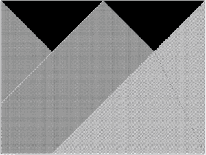
Rule 30 with a non-random seed:

Rule 30 with a random seed:

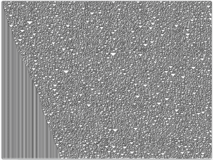
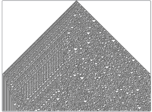
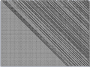
Rule 114 with a non-random seed:

Rule 114 with a random seed:

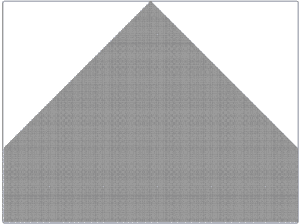
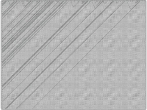
Rule 163 with a non-random seed:

Rule 163 with a random seed:

Reflection
I was able to find patterns in both rule 163 and 114 when I tried them with a random seed, and did not find one with rule 30, as I thought. With a random seed, I.E. the first line arranged randomly, we will see similar iterations for each rule, except for rule 30 and the other rules I could not find a pattern for when I looked at the 256 pictures. This shows that, just like in nature, we can find patterns in randomness. If we extrapolate this into a more complicated cellular automaton, like “Game of Life”, we will see that most patterns of cells tend to stabilize and get into a repetitive pattern relatively quickly, and we will always be able to predict the next iteration, no matter how complicated, which leads me to question the existence of true random behaviors.

References:

“Cellular Automaton.” From Wolfram MathWorld, 18 Feb. 2018, mathworld.wolfram.com/CellularAutomaton.html.

“Elementary Cellular Automaton.” From Wolfram MathWorld, 18 Feb. 2018, mathworld.wolfram.com/ElementaryCellularAutomaton.html.

“The 256 Rules.” Stanford Encyclopedia of Philosophy, Stanford University, 12 Dec. 2018, plato.stanford.edu/entries/cellular-automata/supplement.html.