Midterm Post – Scavenger Robot – Andres Malaga

Research proposal:

               Konrad and I decided to attempt to recreate the behavior of a scavenger. A scavenger is an animal that feeds off of carrion (the decaying flesh of a dead animal). The only animals who are purely scavengers are vultures, since they are able to identify carrion while they fly and thus can find food more easily than terrestrial (land) animals. There are terrestrial animals who scavenge, but they don’t rely solely on this, they also predate. Such is the case of wolves, foxes and hyenas, just to name a few. In order to see how the behavior we wanted to imitate was like, we watched a video by BBC Earth that shows a crow, a group of vultures and a fox feeding on a dead cow’s carcass. We saw that the crow landed on top of a dead cow and started inspecting it, then a flock of vultures arrived and also started inspecting the body of the cow and after a minute or so of inspecting the carrion, they started eating it. We decided to imitate this behavior with our robot. We want our robot to approach an object, round it and inspect it to determine whether or not it is food. The idea is that the robot uses its ultrasonic sensor to measure the size of the object it is going around and determine through changes in its measurement whether it is of ideal size, too big, or a wall, thus determining whether or not the object is food. The embedded video is the video we saw to come up with the idea for the behavior.

Documentation:

               We were looking at different animals’ behavior and Konrad said he was thinking about making a robot that could identify whether an object was food or not; I then associated it with a scavenger, so we started planning how we would mimic the behavior. We first thought of using a pointed temperature sensor (which ended up only working with Arduino) along with the Kittenbot’s ultrasonic sensor, but ultimately just used the latter, as it would take a lot of work to connect the Arduino to our Kittenbot and program it so that it preferred objects within a certain temperature range. Thus, we decided to go on only using the ultrasonic sensor. No components other than the Kittenbot were used. We chose to program the Kittenbot to approach an object to a certain distance at a constant speed and move around it with its ultrasonic sensor pointed at it so that it measured the distance between the object and itself. The idea was that once it detected the distance increased it would do a 90 degree turn and repeat the same assessment, determining whether or not the object is small enough for it to ‘eat’ (if it kept advancing in the same direction for a long time it would have interpreted it as a wall), representing the “eating” with a sound and displaying ‘eat’ on the microbit’s screen. Once Konrad programmed the robot to behave that way (I couldn’t contribute much to the programming, since I don’t know much python), we found out that it ended up detecting anything but food, so he decided to reprogram it so that it moved more slowly and in a circle, which would give more precise readings and would result in the robot not spinning in circles because the distance was beyond the threshold, which was the main problem we found.

It ended up working like this:

Here is the code we used:


  1. from microbit import *

  2. import music

  3. import robotbit

  4. counter = 0

  5. initMovesCount = 12

  6. circleMovesCount = 60

  7. radius = 125

  8. def initialMove():

  9. global counter

  10. degree = 0

  11. if (counter < 10):

  12. degree = counter * 10

  13. elif (counter >= 10):

  14. degree = 100

  15. robotbit.servo(0,90-degree)

  16. robotbit.motor(1, 100, 50)

  17. counter += 1

  18. sleep(50)

  19. def initialMoves():

  20. global initMovesCount

  21. for i in range(int(initMovesCount)):

  22. display.show(robotbit.sonar(pin1))

  23. initialMove()

  24. def circleMove():

  25. global radius

  26. robotbit.motor(1, radius, 100)

  27. robotbit.motor(4, radius * 2, 100)

  28. sleep(100)

  29. def circleMoves():

  30. global circleMovesCount

  31. d = int(robotbit.sonar(pin1))

  32. isFood = True

  33. counter = 0

  34. for i in range(int(circleMovesCount)):

  35. d = int(robotbit.sonar(pin1))

  36. if (d < 1 or d > 50):

  37. isNotFood()

  38. break

  39. circleMove()

  40. counter += 1

  41. if (int(counter) >= 59):

  42. display.scroll('FOOD!!!')

  43. def foodNoticed():

  44. global initMovesCount

  45. global circleMovesCount

  46. initialMoves()

  47. circleMoves()

  48. def isNotFood():

  49. display.scroll('NAAHT')

  50. robotbit.motor(0, 100, 500)robotbit.servo(0,90)

  51. sleep(500)

  52. while True:

  53. d = int(robotbit.sonar(pin1))

  54. if (d < 1 or d > 50):

  55. foodNoticed()

  56. else:

  57. robotbit.motor(0, 100, 500)

  58. robotbit.motor(1, 100, 300)

  59. sleep(500)

  60. #sleep((initMovesCount * 50) + (circleMovesCount + 100))

Midterm Post (Pedestrian Safety Stoplight) – Andres Malaga

I come from Lima, Peru, a city where traffic accidents are the norm in some parts of the city. In the year 2017, it was reported that for 70% of the total traffic accidents that occurred in Lima, it was a pedestrian who was either at fault or injured. Therefore, I proposed to Jackson we tweaked a pedestrian traffic light so that it acts not only as a warning, but as a deterrent too for people wanting to cross when the light was red. The idea was that during the red light period, the traffic light detected whether someone was attempting to cross and sound an alarm. We looked at similar concepts that were already implemented in other countries in order to figure out how we would get this to work and be interactive at the same time. In this case, the user will interact with our project by following the traffic light’s cues (red is stop and green means go), and not following that would result in our traffic light sounding an alarm. We looked at a video that showed different ways different cities in China tried to deter jaywalkers from crossing, many of them too complicated for our current skill level with programming, supplies available, and time. After watching the video, we decided we would create a barrier with a laser that would activate a speaker if ‘broken’. The video we watched is embedded below:

We decided to use a laser aiming at an LDR (Light Dependent Resistor), which would measure the intensity of the laser and act like a tripwire (once it stopped detecting the laser, the value it read would surpass a threshold and activate a speaker). There, we ran into our first problem: we would have to put the LDR on the other side of the table using a very long cable which could be stepped on and would be unstable, thus, our professor (Rudi) gave us an acrylic mirror which we used to reflect the laser into the LDR. It proved to be stable and allowed us to aim the laser into the LDR while keeping them both in the same spot. We tried this for distances up to 1.30 meters (the distance we estimated would be between tables for the user testing session) with favorable results (the laser was reflected into the LDR and giving consistent values). We then added a speaker to the mix and programmed it so that when the laser was interrupted it played a tune.

We first tested it aiming the laser directly at the LDR, to ensure the program did what we wanted it to do (which it did), and then proceeded to set it up again with the mirror. The speaker would play an RTTL tune, since those were what occupied the least amount of memory. Our professor showed us a webpage with a list of tunes and the code that would make the Arduino play them, which we used. The list included tunes similar to the Star Wars theme song and the Top Gun theme song, which did not resemble alarms (they were all snippets from popular movies’ theme songs), so we picked the first 5 notes from “The Good, the Bad and the Ugly”, which were the ones that resembled an alarm the most. We tested the full ‘tripwire’ assembly with the mirror, again at full distance, and got the results we wanted, so I started to work on the traffic light while Jackson did some final adjustments.

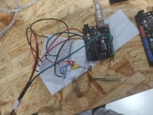
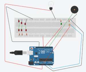
After we got the tripwire done I started to work on the lights. Before doing that, however, I worked with Leon (an IMA fellow) to design and laser-cut the box that would house our project. It had two large round holes on one side we would cover with paper so that the light emitted by the LEDs was diffused and it looked like a real traffic light, two smaller holes on the side from which the laser and LDR would work, as well as a USB-sized hole in the back to power the Arduino and connect it to our computer to tweak, edit and improve the code in real time. We decided we would not use a yellow light, and thus would just use red (on top) and green (on the bottom). We first thought about using only one LED per color, as we though the light would get diffused, but it was too dim, so I experimented with 6 LEDs connected in parallel but to the same source of power, which did the trick; however, Nick (an IMA fellow) warned me that I could exceed the Arduino’s power output, and thus recommended that I arranged the LEDs in 3 groups of two LEDs connected in series, each to a 220 Ohm resistor, to the same power source and ground. With this arrangement, the light was strong enough so that it was visible when diffused. I tried to do the same with the green light; however, the LED by itself was too dim, so Tristan (an IMA fellow) gave us a larger, brighter green LED (we were using 5mm LEDs up to this point, and kept doing so for the red light), which did the trick when we connected it as a traditional LED. I then tweaked the “Blink” example in the Arduino to alternate the two lights, like a traffic light would. After we made sure we had the circuit and program ready for both parts of the project (the tripwire and the traffic light), we proceeded to put them all into one large breadboard and Arduino, trying our best to avoid a wire-spaghetti. The final circuit looked like this (because I couldn’t find a laser icon on Tinkercad, I represented it with a lightbulb, and the speaker we used is represented with a piezo for the same reason):

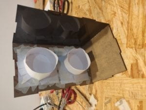
And the box, prior to being assembled, looked like this:

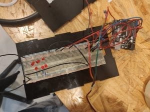
We thought the best way to combine the codes would be to create an if statement below the function that turned on the red light and paste Jackson’s code below. However, it wasn’t that simple, the speaker wouldn’t sound when we tripped the laser. Tristan told us to use the functions “millis” and “long” instead of a delay (since a delay just stops any code from running), and use a while statement instead of an if statement, so that the Arduino kept track of when it would start to look out for the laser being tripped. After we finished the code, we fit all the components into the box and hot glued all but three sides and the top of the box, so that we could make adjustments if necesary during the user testing. This is how the device ended up looking like:

For the user testing we were first given a table in a position where we were unable to set up the mirror on the other side of a walkway, so we were moved to another table that was in a position where we could set the mirror up, albeit this time it was a much longer distance (I estimate it was between 2 to 3 meters), so Jackson took more time to aim the laser towards the LDR. During testing, we realized we had to signal a walkway and the way we wanted the users to walk through so that they would understand our aim (this is something that would not happen in a real life setting, as a pedestrian stoplight is always at the other side of the street, so the user walks towards it instead of past it). Users told us that they didn’t see the laser and that they should see it so that they know they do not need to cross, they said the same thing for the traffic light (it was only visible from one side); however, the point was that the users followed the rules traffic lights have: that red is stop and green is go, and those who do not follow the rules (i.e. attempting to cross on a red light) would be deterred by the alarm coming off of the speaker, something we were able to achieve, as many of the users who tried to cross on a red light asked what was going on when they heard the alarm.

In the group project, I defined interaction as the input and output of information between one human, animal or machine and another (or more) human, animal or machine. The device we made for the project is, through the lights, giving information to the user, telling them whether or not it is safe to cross, and the user is giving the device information through their action of crossing or not. If the user trips the laser (crosses the road while on a red light), the LDR on our device receives an input that tells the device that someone is attempting to cross and sounds an alarm as an output, which should stop the user from crossing and have them back off. The aim of our project was to show that there are ways to attempt to decrease the amount of traffic accidents that happen because of jaywalkers, something that has already been done here in China, but we also wanted to show that we didn’t need to take drastic measures such as shaming jaywalkers by showing their photos on a screen or spraying them with water, a simple alarm will do, and I believe we accomplished our objective. Regarding the suggestions given to us during our user testing, I find them hard to implement on our device because we designed it as the prototype of a concept. If we had more space and resources, we would build it like a proper traffic light and have the sensors on the other side of the street, as well as using more evident deterrents, such as playing a “do not cross!” recording instead of an alarm. If implemented well, this could help drastically decrease the accidents for which jaywalkers are at fault, partly because the device that showed them whether or not it was time to cross the street is now interacting with them telling them they are at risk if they cross on a red light, it gives the pedestrian traffic light a more active role in the pedestrian’s experience, and potentially make the streets safer for cars and pedestrians alike.

Group Project – Andres Malaga – Super Cup

The definition of interaction I would propose is “the input and output of information between two or more humans, machines or animals”, because when we interact with something, we give that something information (input, could be the push of a button, turning a lever or waving towards it, for example), that something processes it and produces information we can then process too (this would be the output, which could be, among other things, motion, a sound or light). Thus, interaction requires a physical or digital input and a physical or digital output, it can’t be only output, like a movie, or only input, like an unplugged keyboard. It has to have both; a TV, for example, is interactive since the human interacts with it using the built-in buttons and the connected remote controller; so is a car, a radio and a phone, some requiring more involvement from the user than others. A car, for example, requires the driver to be constantly stepping on a pedal and steering a wheel, producing a clear output from the car, which ‘processed’ the information that it was given and followed what it indicated, while a TV doesn’t need any inputs from the user after it has been turned on. A car, then, is more interactive than a TV, because at moments the TV stops being interactive while it’s turned on, because it doesn’t depend on a constant interaction. For something to be truly interactive, it should require constant inputs and outputs while it is turned on, like a car or a gaming console, and therefore, should have a user who interacts with it instead of a viewer that just watches it.

The project I chose that does not align with my definition of interaction is “The Bomb”, a film showcased at an installation at a film festival. The installation was designed to immerse the viewers into the story, with screens that were placed around a circular room (they were arranged so as to be viewed at any angle) and live music. It was supposed to make the viewer feel like they were inside the film, but, as much as it generated the sensation in the viewer, which is not a user, it was not at all interactive, the viewer did not need to input anything to get the output, it was just information coming out of the screen and speakers, produced by both the video player and the band playing in the room. The embedded video can better explains the installation:

The project I chose that aligns with my definition of interaction is “Marbles”, an installation of molded shapes in Amsterdam. It consists of shapeless sculptures (just blobs) that light up and produce sounds when the user gets close to them, touches them, or otherwise gives them a physical input, producing a different output depending on the type of the input, be it lighting in a different color for a longer or shorter time or producing a longer or shorter sound. I believe it is interactive because it follows the input-output of information I defined as interaction, since the input would be the person’s activity and the output would be the sound it produces or changing the color of the light it emits. I was not able to find an embed code for the video, but the article is in the following link:

https://www.vice.com/en_us/article/vvz8kj/interactive-public-sculptures-respond-to-human-touch-and-provide-a-digital-playground-for-residents

For the project, we designed a robot that would bring a cup of water after it heard cue phrases, such as “I’m thirsty” or “I need water”, receiving an input of information, telling it that it needs to perform the action, thus activating it and making it look for a source of water, and then bring the cup of water to the user (that would be the output). Therefore, the user is able to produce an input and receive an output, while the robot is able to receive the input and produce the output, according to what the user indicated, thus being interactive.

Articles Cited:

“An Experience At The Heart Of Nuclear Annihilation”. Vice, 2017, https://www.vice.com/en_us/article/3kvwaw/an-experience-at-the-heart-of-nuclear-annihilation.

Holmes, Kevin. “Interactive Public Sculptures Respond To Human Touch And Provide A Digital Playground For Residents”. Vice, 2012, https://www.vice.com/en_us/article/vvz8kj/interactive-public-sculptures-respond-to-human-touch-and-provide-a-digital-playground-for-residents.

Lab 4 – Braitenberg Machines – Andres Malaga

  1. Plan

From now on, we will start to use Python to program the kittenbot. I had problems when using MuEditor, so I will use Atom to write the code. I decided to program my kittenbot to move when an object was between what the ultrasonic sensor determined was between a distance of 15 and 100 units, slowing down as it got closer, as if it was curious or afraid of what it was.

  1. ProgramThe code I wrote (with help from Tristan and Rudi), that ended up working, was this:
    1. from microbit import *

    2. import robotbit

    3. while True:

    4.     d = robotbit.sonar(pin1)

    5.     if d > 10 and d < 100:

    6.         s = d * 2

    7.         robotbit.motor(1, s, 0)

    8.         robotbit.motor(3, s, 0)

    9.     else:

    10.         robotbit.motorstop(1)

    11.         robotbit.motorstop(3)

    When I tested it, it advanced towards my leg and then stopped  once it got close, and kept doing so as I moved around as long as my leg was at a distance the ultrasonic sensor could see.

  2.  Analysis and reflection

An example in nature that behaves similar to how my robot behaves could be a predator, like a tiger or a bear, they follow the prey while hiding and then surprise them. Of course, the latter part cannot be replicated by a robot as simple as this one, but there is definitely room for improvement in the first part, specifically callibrating the speed of the motors so that the robot moved in a straight line and check the function so that the motors always have enough power to move until they need to stop. 

Lab 3 – Building the Kittenbot – Andres Malaga

  1. Building the Kittenbot

The main challenge I had when building the Kittenbot was working with the screws and nuts. I had some experience assembling stuff, mainly with Lego’s and helping my father repair things at home, so it was relatively easy, safe for a few times where I had to screw in a special kind of screw or nut. The most difficult part was wiring the wheels and ultrasonic sensor to the board, since the cables had to be twisted in awkward positions in order for them to be organized.

  1. Testing it and programming it

Since it uses a microbit microcontroller, I used the drag and drop interface to program the robot to move forward and backwards, and the Servo motor attached to the ultrasonic sensor to rotate, in order to test that all the parts were in working order. I noticed one of the wheels is a different size than the other, so it may bring problems when trying to get the Kittenbot to move in a straight line.