Recitation 7 – Serial Communication – Andres Malaga

Exercise 1:

I used two potentiometers, connected to pins A0 and A1. Each potentiometer sent a value to the Arduino, which sent both values in the form of an array to processing. In processing, I coded a canvas the size of the maximum value the potentiometers would give me (672, although it should be 1024) with a white background and a red circle with a fixed size. I coded the circle’s X coordinate to be the value obtained from A0 and made A1 be the Y coordinate. I only had the background in void setup so that it didn’t refresh every frame and the circle could move through the canvas giving the impression that it was drawing something. In this exercise, the interaction was done through the potentiometers, which dictated the position of the circle on the canvas.

Exercise 2:

I made a 1000 x 1000 canvas in processing, and coded for the mouse’s X coordinate to be the first value sent (Values [0]) and the mouse’s Y coordinate to be the second value sent (Values [1]). In Arduino, Values [0] would transform into the frequency of the tone played by a buzzer connected to pin 9, while values [1] would transform into the tone’s duration. In this exercise, the interaction was made through the mouse in processing, whose position would function as an input that would output a tone in the buzzer connected to the Arduino.
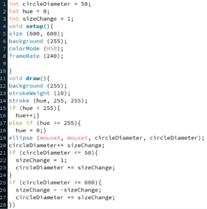

Recitation 6 – Processing Animation

Recitation Exercise:

I made a square whose position is controlled by the mouse that moves in a 1000 x 1000 canvas. The background of the canvas is set to change whenever key ‘b’ is pressed to a random color defined by three random R, G and B values. I made the square not have a stroke and changed rectMode so that the mouse would point at the square’s center instead of its corner. In order to change the background, I coded a ‘void keyPressed’ that I would call upon during void draw. The most interesting functions I called upon were: keyPressed, which makes the program detect when a key (which could be specific or not) is pressed, and rectMode, which changes the way the rectangle’s code is interpreted. A video of the animation and the code I used can be found below:

float r = random (255);
float g = random (255);
float b = random (255);
int r1 = (int(random(255)));
int g1 = (int(random(255)));
int b1 = (int(random(255)));
void setup (){
size (1000, 1000);
background (r, g, b);
rectMode (CENTER);
}

void draw (){
background (r1, g1, b1);
size (1000, 1000);
noStroke();
fill (r, g, b);
rect (mouseX, mouseY, 50, 50);
if (keyPressed == true){
background (r1, g1, b1);
}
}
void keyPressed (){
if (keyPressed){
if (key == ‘b’){
r1 = int(random (255));
g1 = int(random (255));
b1 = int(random (255));}

}}

Homework:

As I use windows, I was unable to record my screen, the video was taken with my phone

Recitation 5 – Processing Basics – Andres Malaga

Recitation 6: Processing Basics

I chose to try and replicate the crest of Wolverhampton Wanderers, a soccer team from England. I chose to replicate this logo because it mostly consisted of geometrical shapes that would be easy to code in processing and would allow me to understand a bit how processing’s programming language works. The logo consists of three hexagons of different colors, one inside each other, and a wolf drawing in the middle. For this exercise, I tried two methods of re-creating the three hexagons (both of which resulted in the same image). The first method consisted of coding 6 triangles that met in the center of the canvas and formed the first hexagon, a process I would repeat three times, changing the coordinates of the triangles so that the hexagon became smaller every time. The second method was by drawing 2 ‘quads’ for each hexagon, each of which would take the shape of three of the triangles together (form a half-hexagon) and change the coordinates so that the shape became smaller for each hexagon I drew. In the end, my drawing was similar to the logo’s hexagons, it only lacked the wolf drawing inside, which would be really difficult to draw using a polygon. It could be drawn using a combination of triangles and rectangles and the right coordinates in the canvas; however, I think drawing the three hexagons allowed me to grasp the basic idea of drawing with processing.

‘Motif’:

Code used:

size (600, 600);
background (100);
stroke (0);
fill(0);
quad(300, 100, 100, 200, 100, 400, 300, 500);
fill(0);
quad(300, 500, 500, 400, 500, 200, 300, 100);
stroke (255);
fill(255);
quad(300, 120, 120, 210, 120, 390, 300, 480);
fill(255);
quad(300, 480, 480, 390, 480, 210, 300, 120);

stroke(253,185,19);
fill(253,185,19);
quad (300, 130, 130, 215, 130, 385, 300, 470);
fill(253,185,19);
quad(300, 470, 470, 385, 470, 215, 300, 130);

Image produced:

Recitation 4 – Drawing Machines – Andres Malaga

Exercise:

We used an H-bridge to run a stepper motor. Because the components needed for this recitation could end up damaging my computer, I chose to check out a Mac from the ER. Due to time constraints we were only able to complete steps 1 and 2. For step 1, we assembled a circuit that allowed the stepper motor to turn on its own. For step 2, we had the rotation of the stepper motor depend on the value obtained from a potentiometer.

Questions:

Question 1:

I am interested in building machines that could help people who are undergoing physical therapy and/or need prosthetics. A stepper or servo motor could be used in a prosthetic arm or leg to regulate the movement of the limb’s elbow, knee or ankle, as their rotation can be limited to become similar to a real joint. Although a prosthetic arm or leg will serve a more practical purpose rather than an artistic one, the actuators involved (a stepper or servo motor) can be used to create art, their rotation could be used to regulate a light show, for instance, or they could be used to move a device that paints on a surface based on readings from a camera, which would be similar to an interactive mirror.

Question 2:

I chose ‘Centripetal Sound Machines’ by Matt Heckert. I think it’s really interesting how Heckert wanted to create the sensation of being inside a mechanism, but I don’t think he was able to achieve it, as the audience was always looking at the installation from the outside instead of looking at it from the inside. He chooses the correct actuator for his project to work, as the motors he chose are able to move the rings up and down and raise and lower a bar that strikes the rings to play the sound. I think Heckert chose the actuators he used bearing in mind the purpose they would serve. For the bars that struck the rings he probably chose a servo because he could regulate the angle at which the rotation stopped and the bar was raised. For the system that lifted and lowered the rings he probably chose a conventional motor, as it would let the ring’s system function like a pulley that continuously raises and lowers the ring.

Preparatory Research and Analysis – Andres Malaga


During the group project, I defined interaction as the input and output of information between two or more humans, machines or animals, and stuck with the definition for the midterm project (I made my device to conform to that definition). I still believe this to be a suitable definition of interaction; however, it should be limited to humans and machines, as animals would fall beyond the scope of this course and don’t necessarily interact with machines. I believe interaction will always involve an input of information which will be processed and produce an output of information (be it in the shape of a click, words on a screen, a sound, among other things). With this definition in mind, I looked for a project that conformed to this definition and one that did not.

The first project I researched is one that aligns with my definition of interaction. “New Angles” is an LED installation by Super Nature which consists of a panel of LEDs that lights up in a different way depending on gestures made by a user. I find this installation aligns with my definition of interaction because it shows a clear input, processing and output of information, the input being the gestures and position of the user, which is received by a camera mounted on the installation, which produces the output, LEDs lighting up in different patterns, this installation needs the user to function, thus making it interactive. I was unable to find a video of the device working, however, there are pictures of it on the website I consulted, which is linked below:

super nature: ‘new angles’ interactive light installation

The second project I researched is one that does not align with my proposed definition of interaction: a recreation of Columbine Schools’s auditorium at the Whitney Museum of American Art, by Bunny Rogers. It consists of a recreation of the school’s auditorium seats and a video of the rest of the auditorium projected on a screen watched by the people seated on those seats. This installation does not conform to my definition of interaction because the viewers do not have to give any input to a device in the installation to receive its output, it is just a one-sided communication, meaning that this installation could perfectly function without anyone sitting there (the video could still be played). A description of the installation can be found here:

https://www.vice.com/en_us/article/ywwg4g/american-artist-columbine-auditorium-whitney-bunny-rogers

Having seen these two examples of interactive projects, a better definition of interaction would be “the exchange of information between two or more humans or machines”, because an input is information that is processed in order to produce an output, a process that could happen both from human to machine and from machine to human.