Herding Commands Adapted to a Microbit – Andres Malaga

Abstract:

The aim of this experiment is to translate the commands given to herding dogs into instructions given to a robot through a controller device in order to start replicating herding behavior. An example of a herding robot already in development and a mathematical model that describes the principles of herding behavior are discussed as examples of the implementation of the herding commands. The robot used in this experiment was only able to receive and follow commands related to its movement, but further improvements to this have been discussed that could lead to the development of fully autonomous robots that are capable of carrying out the functions of a herding dog.

Bio-Inspiration:

The behavior I am going to investigate is herding behavior such as that observed in herding dogs. A herding dog (or sheepdog) is a dog that has been trained to keep together a group of sheep or cattle through commands. The efficiency of a sheepdog relies on its ability to group the animals and move them forward. When grouping sheep, a sheepdog will attempt to move the sheep close to each other, thus closing the gaps between them, and lead them from the back of the group. This first step is done so that the sheep (or cattle) move in a uniform manner in order to facilitate the second step, which is leading the group from behind. The second step consists of the dog staying behind the group, prompting it to move forward. In order to close gaps between sheep or cattle, the dog will usually go towards the stray sheep or cow and bark at it, prompting it to return to the group. The sheep will always move away from the dog. Herding dogs are trained to herd responding to commands by their owner, which usually include commands that make the dog turn left, right, go straight, get closer or away from the herd, group the animals, stop, and bark.  These commands are often said by the owner or given in the form of a whistle, where different pitches or patterns can symbolize a different command. In this experiment, I will try to make a kittenbot follow instructions similar to the herding commands given by a microbit as the first step towards developing autonomous robots that can carry out herding efficiently, such as the Swagbot.

Herding Robots:

Herding robots are already in use. An example of this is Swagbot, a robot developed in Australia meant to group and lead cows around a pasture. This robot just attempts to keep the group together and lead it around, following the principles of herding behavior. Although it does not follow any external commands like a herding dog would, the actions it needs to do are already programmed so that it follows the principles of herding behavior. This robot is autonomous and can detect the herd and members of the herd getting away from it, prompting it to close the gap and maintain cohesion while leading the group. The behavior of this robot resembles a mathematical model that explains herding behavior, which is essentially derived from how herding dogs follow the commands given to them.

Mathematical model for herding behavior:

The principles of herding behavior have been mathematically modeled and found to be applicable in different fields, since herding behavior can be seen as a way of achieving and maintaining cohesion within a group of elements. The principles are two: the herder (in this case the sheepdog) has to keep the group together, and the herder has to drive the group forward. The sheepdog keeps the group together by closing gaps between members of the group that have gone astray. This is achieved by getting in front of the stray animal, which will always move away from the dog and towards the group. The herder moves the group forward by leading it from behind, as the sheep will always move away from the dog. The dog will cycle between keeping the group together and moving it forward. This mathematical model has been proven to resemble the behavior of real herding dogs, and could be applied in different fields such as human crowd control, cleaning of debris and control of swarm robots. Although my experiment will not center on or implement this mathematical model, a herding robot could be programmed to follow this mathematical model and use computer vision with an ultrasonic sensor to carry out herding on its own, as the mathematical model already takes into account the commands given to a herding dog.

Design and Purpose of the experiment:

Because a robot that replicates herding behavior already exists and so does a mathematical model that explains this behavior, my experiment will center on the commands herding dogs receive and attempt to replicate them with a kittenbot in order to prove that in a larger context a remote-controlled robot will be able to carry out herding as efficiently or more efficient than a herding dog. This would be the first step towards creating an autonomous robot that can carry out herding. While the experiment will be carried out only with microbits (which use radio signals), it is worth stating that it should work with different kinds of communication, such as Bluetooth and voice input, provided the necessary hardware and software is available. The experiment will also focus only on commands related to locomotion, sensors could be added to allow the robot to sense distance on its own and group the herd on its own.  A LearningBot that turns when it detects things in front of its ultrasonic sensor will be used as the subject to be ā€˜herdedā€™ by the kittenbot.

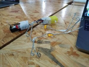
Materials and software needed for this experiment are:

  • Two Microbit microcontrollers
  • One kittenbot (or any robot that supports microbit) fit with two wheels, each attached to a different motor.
  • Microsoft MakeCode (to write the code for the microbit) or MuEditor (to code microbit in python). MakeCode was used for this experiment.
  • One LearningBot, fitted with two Servo Motors attached to wheels and an ultrasonic sensor. The robot was pre-programmed via Arduino to turn right when it detects objects in front of it.

Procedure:

  • Both microbits were programmed using MakeCode to send and receive numbers through their built-in radio transmitters.
  • A different number was programmed to be sent depending on the gesture performed with or on the microbit, such as a button or buttons being pressed or the microbit being physically tilted sideways.
  • The microbits were programmed to receive the numbers and use a series of ā€œif ā€ and ā€œelse if ā€ statements to determine the command the number gives. The same code was flashed into both microbits.
  • One microbit was left connected to the computer (which could be replaced with any other power source, such as a power bank, a wall plug or batteries), and the other one was plugged into the kittenbotā€™s microbit slot.
  • The kittenbot was turned on, able to be controlled via the microbit connected to the computer.
  • If a LearningBot is used, it will turn right when the kittenbot passes in front of it.

Code:

            The microbits were programmed with Microsoft MakeCode. They were programmed using MakeCodeā€™s drag-and-drop feature, which created a version of the code in JavaScript on the background. The JavaScript version of the code is shown below:

  1. let State = 0
  2. onButtonPressed(Button.A, function () {
  3. sendNumber(0)
  4. })
  5. onReceivedNumber(function (receivedNumber) {
  6. if (receivedNumber == 0) {
  7. MotorStopAll()
  8. showString(“F”)
  9. MotorRunDual(
  10. Motors.M1A,
  11. 150,
  12. Motors.M2B,
  13. 150
  14. )
  15. } else if (receivedNumber == 1) {
  16. MotorStopAll()
  17. showString(“B”)
  18. MotorRunDual(
  19. Motors.M1A,
  20. -80,
  21. Motors.M2B,
  22. -80
  23. )
  24. } else if (receivedNumber == 2) {
  25. MotorStopAll()
  26. showString(“S”)
  27. } else if (receivedNumber == 3) {
  28. MotorStopAll()
  29. showString(“L”)
  30. MotorRunDual(
  31. Motors.M1A,
  32. 150,
  33. Motors.M2B,
  34. 90
  35. )
  36. } else if (receivedNumber == 4) {
  37. MotorStopAll()
  38. showString(“R”)
  39. MotorRunDual(
  40. Motors.M1A,
  41. 90,
  42. Motors.M2B,
  43. 150
  44. )
  45. }
  46. })
  47. onGesture(Gesture.TiltLeft, function () {
  48. sendNumber(3)
  49. })
  50. onGesture(Gesture.TiltRight, function () {
  51. sendNumber(4)
  52. })
  53. onButtonPressed(Button.AB, function () {
  54. sendNumber(2)
  55. })
  56. onButtonPressed(Button.B, function () {
  57. sendNumber(1)
  58. })
  59. State = 0
  60. setGroup(1)
  61. forever(function () {
  62. if (true) {
  63. } else {
  64. }
  65. })


Carrying out the experiment:

            The kittenbot was supposed to mimic a sheepdog carrying out herding behavior. Through giving it commands with another microbit, the kittenbot displayed the first letter of the action and performed it. For example, if it received the command to go forward it would display an F, if it received a command to go backwards it would display a B, it would display R if it had to turn right and L if it had to turn left, and S if it had to stop. The idea behind having the kittenbot display the commands before executing them was to show that the kittenbot was acknowledging the command before executing it, just like a sheepdog acts when given a command. Because there were no sensors attached to the kittenbot, the commands given to it could only be related to the robot moving, with not much room for commands related to herding itself. This made the kittenbot resemble a remote-controlled car more than a sheepdog, but demonstrated that the robot was able to follow commands, setting the base for more complex features to be added, such as sensors and other methods of control.

Conclusions and possible improvements:

The robot acted with little delay after the action in the other microbit was performed, and while it was not equipped with any sensors to detect and group a group of things, it proved that it would be the first step towards creating a robot that carries out herding behavior, similar to a Swagbot. In an ideal scenario the robot would be much bigger and be mounted with sensors, such as an infrared/ultrasonic sensor in order to allow for more commands to be given to the robot, such as keeping within a certain distance of the group, and would also allow the robot to detect stray sheep/cow to close the gap, allowing it to behave more like a real sheepdog. A microphone could be added so that the robot detects voice commands or whistles of different pitches and acts on them, giving the user more control over the robot. Other types of control may also be experimented with. An analog controller (joystick), for example, gives more control over the movement of the robot. In conclusion, a robot will be able to apply the principles of herding behavior with further improvements such as a different interface from which to control it and sensors that give it more autonomy and increase the number of possible commands that can be given to it. Once this is implemented, a fully autonomous herding robot could be developed that has the herding commands written in its code and applies them to the mathematical model for herding behavior.

Works Cited

Association, Press. Sheepdogs Could Be Replaced by Robots After Scientists Crack Simple Process. 27 August 2014. <https://www.theguardian.com/uk-news/2014/aug/27/sheepdogs-replaced-by-robots>.

Klein, Alice. Cattle-herding Robot Swagbot Makes Debut on Australian Farms. 12 July 2016. <https://www.newscientist.com/article/2097004-cattle-herding-robot-swagbot-makes-debut-on-australian-farms/>.

Strombom, Daniel and Andrew King. Why We Programmed a Robot to Act Like a Sheepdog. 21 May 2018. <http://theconversation.com/why-we-programmed-a-robot-to-act-like-a-sheepdog-96961>.

Locomotion and prototyping – Andres Malaga

Molly and I first attempted to mimic a horseā€™s gait, which consists of the horse lifting the front hoof of one side and the back hoof of the other at the same time, alternating them to achieve forward motion. We first tried to replicate that with a design made out of legos connected to a motor. Although it achieved the motion pattern we wanted, it was very difficult to have the motor move the mechanism while it remained stable. The next class, we changed the design and started prototyping a set of ā€˜legsā€™ arranged in the shape of an X (two long straight ā€˜legsā€™, one on each side of the motor), which would spin and bring the motor forward. Molly prototyped the model with two rods of metal, and we then proceeded to create a laser-cut version of it, which involved a ā€˜footā€™ attached to either end of the legs, to provide a bigger contact surface that allowed the motor (which acted as the body) to be propelled forwards. The motor was powered by batteries, which were put like if they were a tail to provide balance to the system. The system no longer mirrored a horseā€™s locomotion, it now mirrored the Common Basilisk, popularly known as the ā€˜Jesus Christ Lizardā€™, which runs over water moving its legs really fast in the same pattern as our system. Improvements could definitely be made to the system, such as making the legs curved instead of straight, essentially resembling a prosthetic lower leg such as that used by former runner Oscar Pistorius, which improves the contact between the foot and the table, allowing it to maybe be more stable. We tried to do a similar thing by adding foam to the feetā€™s contact surface, but it resulted in the system moving as if it was jumping around, instead of achieving a more gait-like motion. The first picture is the prototype Molly did with the metal rods. The video after that is a video of a common basilisk running through water, and the next two are our mechanisms working before and after adding foam.

A light that calms down (Final Project Documentation) ā€“ Andres Malaga ā€“ Rudi

Conception and design:

I wanted to explore how interaction came to be when users came across an object in the middle of a room, drawing inspiration from works that explored interaction in public space (such as ā€˜Marblesā€™ and ā€˜Duneā€™ by Daan Roosegaarde), which had the device light up in different ways depending on how they interacted with passersby. Dune, for example, lit up where the passerby was passing through, and Marbles lit up when passersby touched or got close to one of their devices. I chose to base myself off of ā€˜Marblesā€™ and create a similar scaled down version. Instead of an irregular shape, I just used a hollow dome, since a circle would allow me to place capacitive touch sensors equidistantly, which fed values that became the hue of an LED strip. I first planned to produce only two audio outputs from processing (after I was done with making the device before user testing): the sound of a crowd and white noise, since they would symbolize chaos and tranquility respectively, acting when the lights were chaotically changing colors (as the capacitive touch sensors would detect very different values that became really unstable). The unstable values somehow fixed themselves before the presentation, which allowed me to get the results I wanted (colors transitioning smoothly). With this color output, Rudi helped me code a multiple-value serial communication that had two sensorsā€™ values affect the frequency of a sine wave and the other two affect the amplitude, leading to a device producing a sine wave that would actually look and sound like it calmed down. The dome was 3-d printed in white PLA and was glued to a white laser-cut circle, an Arduino Uno was used to house the program, with 4 capacitive touch sensors and an LED strip connected to it. A capacitive touch sensor consists of a resistor connected to a wire wrapped in a piece of copper tape, which detects changes in an electric field a few inches away from it. Another option for the dome were white acrylic bowls, which I tested my device with but ended up not using because they did not diffract the light as well as the 3-d printed dome. The first video was the first iteration of the device, before sound was added. The second video is the final device, after the sinewave from processing was added.

Fabrication and Production:

In the process of 3-d printing the dome, the filament broke twice, so I had to change the printer and filament. The dome finished printing in time to be incorporated with the circuit for the user test. Regarding the circuit,  I elected to use sensors that gave an unpredictable range of values and unstable readings, which made it difficult for me to find a maximum value to map. I ended up constraining the values between 0 and a value I estimated was high enough, and mapped that same range to be from 0 to 255 so that they could ā€˜feedā€™ a color to the LED strip. The LED strip was configured to work in HSB so that the hues flowed smoothly. During the first part of the project, the values obtained by the sensors were so unpredictable that the dome ended up changing colors almost randomly. Because of that, I ended up programming the sound output to be the crowd and the white noise. However, during user testing the main feedback I received was that in doing so I turned the device into an on/off switch for two different sounds and killed the sensation of the light calming itself down. After the user test I found that the values obtained by the sensors had become stable, which allowed me to constrain and map them more accurately, having a device with colors that would actually flow smoothly. Then Rudi helped me code a sine wave whose frequency and amplitude were affected by the values obtained by the different sensors, decreasing along with the distance between the userā€™s hand and the device. Users then stated that they felt like they were actually calming down the device, which prompted me to record a video of myself interacting with the device (shown below) which I later showed during my presentation, since it was the only time the device worked the way I wanted it to work. After that, the device started changing colors chaotically again. During the testings I conducted with this second version of the device, I tried to tell the users the least about what they had to do with it, but I eventually had to give them some information about it. I think it may be because it was in a classroom setting instead of in the street or the hallway, which would have allowed the users to interact with the device more freely. However, I believe I was able to see how the users discovered what the device did, albeit after a little guidance.

Conclusion:

My project aimed to find out how interaction came to be between a user and a device in the middle of public space. Due to the 3-d printer only being able to print small objects, I changed from ā€˜public spaceā€™ to ā€˜tabletopā€™, as it was, essentially, how my project would be laid out. The way users interacted with it led me to think that I would be able to investigate my question further with an installation in the middle of the street, which is what I would do if I had the resources and time. I believe the results of my project align with my definition of interaction because it is based on the processing of an input turned into an output, between a human and a device. If I had more time, I would attempt to improve the design of the dome that houses the device and give it an irregular shape, similar to those found in nature, like a rock, and use more accurate sensors instead of makeshift ones made out of stripped wire, as well as have a bigger variety of sound produced that made it seem like the ā€˜rockā€™ was alive, which would prompt the user to interact and discover more with it. In conclusion, I believe this project was successful in letting me observe how interaction comes to be, but there is still a lot of room for improvement that could let me answer the question better, especially when it comes to users discovering the functions of the device.

Recitation 9 – Media Controller – Andres Malaga

I made a circuit with 2 potentiometers connected to the Arduino, which would manipulate the size of the pixels in the image obtained by the webcam in processing. One of the potentiometers would control the width of the pixels and the other one would control the height of the pixels. I made the pixels have no stroke so that the canvas didnā€™t turn black when either the height or width was too small. For this exercise, I donā€™t think I used computer vision, since I didnā€™t have the camera detect anything, I used an analog input from the Arduino which resulted in the size of the pixels in the camera changing.

Final Project Essay – Andres Malaga

Statement of Purpose:

I feel particularly drawn towards installations put in public space (in the middle of the street for example). There is one installation that caught my attention which made me ask myself how interaction comes to be: ā€˜Marblesā€™ by Daan Roosegaarde. ā€˜Marblesā€™ consisted of a series of irregularly shaped ā€˜rocksā€™ set in the street that would light up and emit different sounds when people touched them, got close to them, or simply passed by them. In my final project, I want to explore how the interaction comes to be when a user finds a device in the middle of space, be it the street, a room or a table.

Project Plan:

I plan to make a device that explores touch input and two outputs: sound and light. The device should ideally be of an irregular 3-d printed shape, which would give it a smooth texture and would ideally be white, almost transparent. The device will be fitted with an Arduino and 4 to 5 sensors that detect the distance between oneā€™s hand and the surface of the device. This distance will then affect the color of either an RGB LED or an LED Strip, which means that the device will change color depending on the distance between the surface of the device and the userā€™s hand. The device will communicate with a processing sketch that uses those values to play different sounds. Ideally, during user testing the device will just be powered up and left there for users to discover how it works, allowing me to see how the interaction between the user and the device comes to be. I have chosen to define interaction as the exchange of information between one or more humans and/or devices in the form of inputs and outputs that are processed in either end.

Context and Significance:

Two installations by Daan Roosegaarde (Marbles and Dune) and one by Super Nature (New Angles) serve as the inspiration for my project, all of them have an input that is processed and produces an output that looks like what I want to achieve in my project. ā€˜Duneā€™ turns a light on when the user passes by and turns it of once the user is no longer in front of it, the lights are arranged in a path, which makes the user feel like the installation is lighting their way. ā€˜New Anglesā€™, on the other hand, is an interactive mirror that changes the color of different LEDs fitted to it based on input from a camera. ā€˜Marblesā€™ incorporates the touch element and uses it to play with the deviceā€™s color as well as producing a sound. I plan to create a device that can get multiple touch/distance inputs and produce multiple light and sound outputs. It would be, in the end, similar to a scaled-down version of ā€˜marblesā€™, but with all the interaction happening in one ā€˜stoneā€™ that can produce different outputs. The idea of this project is that, if it were to be done in a larger context, any person that passes by it could explore their sensations by interacting with it and discovering its different outputs.