Week 1: Recitation Documentation
Recitation 1: Electronics & Soldering
Instructor: Marcela
Circuit 1: Door Bell
Components:
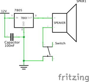
- Breadboard: This is where we plug in wires and connect all the components
- LM7805 Voltage Regulator: It is used to maintain a constant voltage level
- Buzzer: It is used as the speaker in the schematics, which will make sounds when the circuit is connected.
- Push-Button Switch: To turn the speaker on and off.
- 100 nF (0.1uF) Capacitor: It is parallel connected in the circuit. It blocks the direct current and let direct current to pass through the speaker, while it allows alternating current to pass and directly goes to the ground.
- 12 volt power supply: Transfer 220V AC power and supply 12V power for the circuit.
- Barrel Jack
- Jumper Cables (Hook-up Wires)
Process:
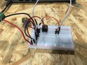
At first, it took us some time to figure out how to provide 12V power supply, as the power source part is not clearly shown on the schematics. We found out at last that we need to connect our circuit to the socket and the equipment we had will transfer the electricity to 12V DC. And then we spent some time to get familiar with the breadboard, as we can’t see which parts are connected inside the board. After knowing exactly how current flows inside the board, things got easier. One last thing that we had trouble with was the ground. There are three components that is connected to it: switch, capacitor and the “GND” of the voltage regulator, so we got a little confused but we solved the problem eventually.
Circuit 2: Lamp
Components:
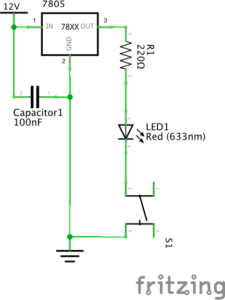
Breadboard, LM7805 Voltage Regulator, Push-Button Switch, 100 nF (0.1uF) Capacitor, Jumper Cables (Hook-up Wires)
- 220 ohm Resistor: It decreases the current magnitude and protects the LED from burning.
- Multimeter: It is used to distinguish the 220 and 10K ohm Resistors.
- LED
Process:
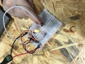
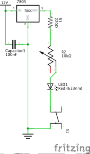
Building the second circuit was easier because we already had the first one. We didn’t have to build it from the start, but only needed to take off the speaker and replace it with the 220 ohm resistor and LED light.
Circuit 3: Dimmable Lamp
Components:
Breadboard, LM7805 Voltage Regulator, Push-Button Switch, 100 nF (0.1uF) Capacitor, Jumper Cables (Hook-up Wires), 220 ohm Resistor, LED
- 10K ohm Variable Resistor (Potentiometer): By changing the resistance of it, we can change the LED’s brightness.
- Arcade Button
Process:
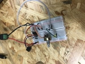
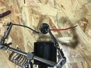
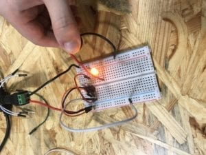
For the third circuit, we also built it based on the second one we already had. We added the 10K ohm variable resistor between the 220 ohm resistor and LED. After that, we went to the soldering station and soldered wires to an arcade button to make it connectable to the breadboard. Then, we went back to use it to replace the push button. While as we removed our completed circuit too early, we had to reconnect it again. And this time we accidentally plugged in the LED in the wrong direction, and it didn’t light up. This is a problem that we should pay more attention to next time.
Reading responses:
Question 1:
The circuits we built are to some extent similar to the refrigerator example in the article. The circuit could be considered interactive, as it listens (to the pressing button), thinks (with current flowing through the circuit in a certain direction), and speaks (by making sounds or lighting up). However, I also agree with the author that it is low-level interactivity, that it does not contain much meaning or thoughts with such interaction.
Question 2:
Interactive art could be created when it involves more thoughts and communications back and forth. In one of the projects that we saw in class, a plant owns its Twitter account by using Arduino and sensors to sense its states and send tweets online. This is a good example of interactivity. And I think the more important part about Interactive Art is not merely reacting to commands, but delivering information or expressing feelings.