Introduction
My partner and I chose to use the joystick model for the third recitation session. We both found it intriguing to control a joystick and have different values correspond with different directions as a result. Our goals for this project were to first correctly set up the joystick module, and also to incorporate it into the three colored LED light which could display red, green, and blue. We wanted to push ourselves into unknown territory with an unfamiliar device at hand. We both felt it would add to our confidence and problem solving skills within the physical set up and code. The initial circuit to test the values of the joystick was relatively simple to set up with only four wires. After testing it out and writing down the X and Y values associated with the different movements, we moved on to the larger task at hand of connecting it to the LED.
Circuit One, Joystick Module Initial Setup
Although the diagram called for five different connections from the joystick module to the Arduino, we only ended up needing four because my partner and I declined to use the key (digital) option and stick entirely with analog throughout the process. After gathering the necessary resources of four jumper wires, an Arduino board, a USB A to B cable, and a joystick module, we were ready to begin. Pictured below is the diagram we used for guidance throughout the circuit building. All credit to Brainy Bits for the image.
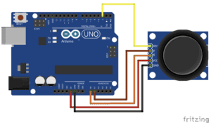
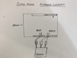
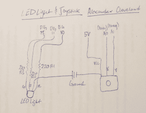
As I previously mentioned, the yellow wire at the top of the diagram was not used in our trials because my partner and I decided to only used analog function with the joy stick. My partner and I used the first jumper cable to connect the X value from the joystick to A0 under analog. We then used a second jumper cable to match that action but instead connected it from the Y value of the joystick to the A1 value under analog. This ensured that the joystick would be able to interact with the inputted code once connected with my partner’s laptop. After doing so, my partner and I connected a jumper cable between the ground power on the joystick to the ground power on the Arduino board. This was just to ensure that the ground power from the Arduino board was flowing into the right input. We then used the fourth (and last) jumper wire to connect the VCC on the joystick into the 5 volts (5V) in the Arduino board. This action completed the wiring portion as we moved onto setting up the code. Below is my own schematic for the joystick module.
The code was under the jurisdiction of digitalWrite because we limited ourselves to only those pin numbers for simplicity purposes. After entering the corresponding pin numbers (A0 and A1) my partner and I uploaded the code and connected the USB A to B cord with the Arduino board. As a result, we were able to see which X and Y values correlated with certain movements of the joystick. The values were as follows:
| X | Y | |
| Left | 0-200 | 519 |
| Right | 900-1023 | 519 |
| Up | 524 | 900-1023 |
| Down | 524 | 0-200 |
A video of the completed circuit can also be viewed here (IMG_2611)
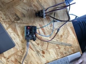
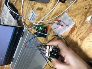
A picture of the completed circuit can also be viewed below.
Circuit Two, Incorporating an LED Light
After setting up the initial circuit with plenty of time remaining, my partner and I decided it would be a fair challenge to set up the RGB LED light in correspondence with three 220 ohm resistors and four jumper cables. The goal of this project was to link the joystick module with the RGB LED light so that a distinct directional movement would dictate the color of the LED.
Below is the schematic we used a reference. This schematic was provided by DFROBOT which was found within the Arduino kit we used.
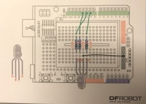
In the initial stage, we plugged in the RGB LED light to the middle of our breadboard. We then used three different 220 ohm resistors to correlate on the same row as prongs G, B, and R. On the other ends of the resistors, we used three jumper cables to connect it into the digital pins of 9, 10, and 11. On the remaining prong of the RGB light, we used a separate jumper cable to source it back to the ground power of the Arduino board. In order to correctly connect the joystick module, we left the original wires from that circuit plugged into the Arduino. In order to tether the interaction between the LED and the joystick, we used two jumper cables and connected one for the positive column of the breadboard to 5V, and one from the negative to the ground power of the Arduino board. After checking the specs on the physical end, my partner and I entered the code with help from Brainy-bits.com and its tutorial on the joystick module. Once complete, my partner and I plugged the USB cable back into the Arduino and uploaded the code. In the first effort, the circuit faulted because my partner and I not noticed that we plugged the LED light in incorrectly. Therefore the wires weren’t corresponding with the correct prongs of the LED, which also led to a fault in our code. As a result, we switched the wires to match accordingly with our code for simplicity. The circuit worked on the second try. A picture of the completed circuit can be viewed below. This picture is depicting the color change when the joystick is moved to the left.
My own schematic for circuit two can also be viewed below.
Conclusion
I enjoyed undertaking the challenge to complete this circuit due to its intricate coding techniques and subtle hardware adjustments along the way. I think it was good for us to use the first circuit as a building block to then incorporate the joystick module later on in tandem with the LED. It gave my partner and I the confidence to deal with an activity we had never done before. Although the second circuit took us two tries, I valued the experience of learning from my mistakes. It was a good lesson that no matter how simple a circuit may look, it can be extremely difficult to physically build. My partner and I underestimated the physicality of this project from the start. It will benefit us later on because it has taught us to approach every project from the same attitude. Although we took the confidence from building the first circuit into the joystick module, we turned that into arrogance and became careless as a result. I am glad we picked the joystick because it was an out of the box project for my partner and I. Having never dealt with a module such as this one, it exposed us to the intricacies that are required to maintain a complex project. By balancing the code along with the physical wiring, I learned more than I could’ve if I had picked a circuit I was comfortable. It should also be noted that I introduced a strategy I had learned from Recitation #2 wherein I became unorganized throughout the wiring process. I created a checklist of all materials used, so it actually helped when eliminating possible malfunctions when the circuit was not originally working.
Questions
- My partner and I intended to assemble an RGB LED light to be controlled by the joystick module. When we would move the joystick to the left, the RGB LED light would coordinate and change colors. This would go on for the three different values possible within the light. A possible real life use for this joystick could be in a traffic light. While it obviously wouldn’t be used everyday since there are automatic sensors for traffic lights, it could be used in emergencies when the light isn’t working properly. If the traffic light were to need manual attention for the intervals of green-yellow-red, this joystick could be used for such an occasion.
- I think it code is compared to a recipe due to its invariability. By this I mean that in order for the code to correlate with the circuit, the letters need to be capitalized a certain way, the pin number has to be exact. The reason recipes exist is because someone else has found the exact number of ingredients and their amounts needed to make the end result taste good. To bake a cake, you need butter, eggs, flour, baking soda, and sugar all baked at a certain temperature. In the end, you get a cake made to the specifications that the majority of people have deemed acceptable over time. The same can be said for coding and wiring an Arduino circuit. If one forgets the baking soda (the pin #) the code will be invalid and the entire project will cease to work correctly. Both a recipe and coding need to be followed exactly in order correctly conduct them.
- I think in my generation especially, computers have affected our behavior in a multitude of ways. I think the most evident is social interactivity. From what I’ve witnessed, a lot of kids have trouble interacting with one another. Not that teenage awkwardness doesn’t still exist, but computers have amplified this behavior through online chatrooms. It’s smuch easier to direct message someone online and have time to think hard and respond. A common example could be in a tense situation wherein both teenagers act like chess pieces, with each one plotting their next move. Having a computer between two voices amplifies the intensity within the conversation. There is less flow and more thinking involved whereas in real life it is based on read and react behavior. When I have a conversation with another human being, I depend on my skills to read someone. So, it’s more based on improvising than having time to think. So in a way, I think computers have my generation more reclusive and less willing to interact for fear of social anxiety.
Sources Used
https://www.brainy-bits.com/arduino-joystick-tutorial/
https://www.dfrobot.com/ (DFROBOT used for reference in Circuit Two)
https://wp.nyu.edu/shanghai-ima-interaction-lab/category/recitations/
great documentation Alexander!
just a couple of things to consider for the next posts:
1. add your code, you can copy and paste it or add a link to it on github: https://github.com
2. never post *.mov videos. Use a free convertor to change the extention to *.mp4, these ones will be displayed on the post as videos and not as links. https://www.onlinevideoconverter.com/
3. It would be better if you copy/paste the questions so someone who finds your post can understand what you are answering.