Introduction
In the second recitation of the term, my partner and I worked on three different circuits involving the Arduino and breadboard components. The goal of circuit one was to create a fade with the given LED light on the breadboard. The goal in circuit two was to create a tone melody, which in simplest form is a short song produced by the speaker on the board. Both circuits were simple with only a few wires involved so they took a relatively short amount of time compared to circuit three. The goal behind circuit three was to use the arcade buttons we picked up at the front and input them into the breadboard to create a game where the first person to ten clicks using the button was the winner. This involved many more wires and also delicate treatment of the wires because there were many bunched together. My individual goals were safety (once again) and also getting the circuit right on the first try. I do value trial and error as it helps me learn more about the process, but at this stage in the class I am beginning to learn more so I also begin to expect more out of myself. Safety is and always will be my first priority when entering these types of projects. As I am still somewhat unfamiliar as to how different wires could react with one another, I make sure to keep the Arduino board unplugged from the computer while moving wires and other pieces around. This ensures that nothing will unexpectedly spark and hurt me or my partner. All resources used for this project were borrowed from the IMA lab in room 826/825 at NYU in Shanghai and also from my own Arduino kit handed out at the beginning of class. The materials used for this recitation are as follows:
From Arduino Kit:
1 * Arduino Uno
1 * USB A to B cable
1 * breadboard
1 * buzzer
2 * LEDs
2 * 220 ohm resistors
2 * 10K ohm resistors
2 * pushbuttons
A handful of jumper cables
From cart:
2 * arcade buttons
1 * Multimeter (optional)
(Material list is sourced from NYU Shanghai Interaction lab syllabus)
Circuit One, Fade
My partner and I started circuit one by reviewing the diagram and collecting the necessary materials needed. This included an Arduino board, a breadboard, an LED light, multiple jumper wires, and one 220 ohm resistor. The original diagram from the recitation post can be pictured below.
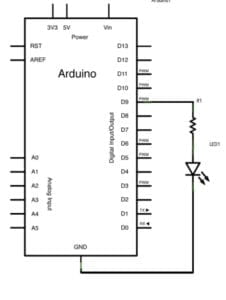
We started by hooking up the breadboard to the power and voltage of the Arduino circuit. This meant connecting a wire from the negative column to the ground power and also a wire from the positive column to the 5 Volts. This gave way for us to insert the resistor and LED light onto the main spread of the breadboard. One end of the resistor was in line with the LED and the other end was connected to a green wire. This green wire (a5) was also connected to pin ~9 on the Arduino board to ensure our ability to manipulate the power through coding. A picture of our initial set up can be seen below.
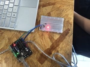
As is pictured above, there is also a grey wire (USB A to B cable) which sources power from the laptop to the Arduino board. It acts as a power tether to connect the computer to the Arduino to the breadboard. It should also be noted that we rejected the optional use of a multimeter for this circuit. In order to access the code we opened Arduino and clicked on examples and then fade. Once we entered the correct pin number (~9) and used digital write to correlate with it, we decided the circuit was adequately set up and plugged the USB cord into the computer to transfer the code. A complete video for circuit one can be seen using the following link (IMG_2568). It should also be noted that my partner and I achieved the correct format on the first try of building circuit one (one of my goals).
Circuit Two, Tone Melody
Circuit two took an even simpler form than circuit one by downgrading from three wires used to just two. The objective of circuit two was to create a melody by using a speaker connected to the Arduino board. A diagram provided by the recitation blog can be found below. For this circuit, my partner and I used an Arduino board, a breadboard, a speaker, and two jumper wires.
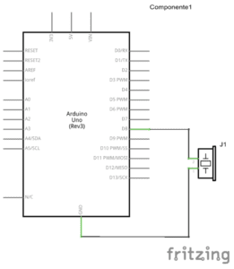
We started by unplugging the USB cable from the computer to ensure maximum safety while adjusting wires and other parts. Following this, my partner plugged in the speaker to the breadboard and I used a wire to connect it from the ground power on the digital side to one leg of the speaker. This ensured that the speaker had proper electricity from the Arduino to make a sound. My partner then plugged a second wire from the other end of the speaker into Digital pin number 8. A picture of the completed set up can be seen below.
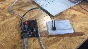
After completing the physical set up, my partner and I entered the corresponding code by using examples from digital to toneMelody. After examining the code, we inputed the values of different tones and notes listed on the Arduino tutorial into a new tab as instructed. After doing so, I plugged in the USB cable to the computer and uploaded the code appropriately. A video of the completed circuit and corresponding song can be found here (IMG_2569). It should be noted that we completed this circuit successfully on the first try again.
Circuit Three, Speed Game
The goal of circuit three was to create a two player game wherein each player presses a button as fast as they can and whoever reaches ten clicks first is the winner. In order to understand the physical design and code, we first had to use Tinkercad’s online resource as a guide. A diagram of the circuit from their website is pictured below. (All credit reserved to Tinkercad online)
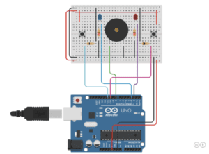
Considering the amount of wires my partner and I were dealing with, we decided it would be best if one person were to handle the wires since it would be difficult to split it up and keep track of the other’s progress. So I was tasked with handling the wires and immediately got to work. I started with the two simplest wires, a red wire which stemmed from one positive column to the opposite side positive column. The same was done for the black wire as it went from negative to negative column. After this step, I plugged a black wire from the negative column on the other end of the board to the ground power on the Arduino board. I correspondingly inserted a red wire from the positive column on the same side to the 5V of power on the Arduino board. These two wires now ensured that the breadboard would have power once we plugged the USB wire into the computer. In order to simplify matters, I then plugged the speaker into the middle of the breadboard, flanked on both sides by a 220 ohm resistor which stretched over the middle median of the board so each resistor was connected by both sides. I also plugged in both LEDs so that one leg of each LED light was lined up in the same row as a 220 ohm resistor. These base foundations for the setup gave me better reference to plug other wires in appropriately. I followed this by plugging in a wire from Digital pin 2 to the other free LED leg on the right side of the board. I made a similar move right after this and plugged a wire in from digital pin 3 to the free leg of the other LED light on the left side of the bread board. This ensured symmetry so far within the set up of the board. After, I set up a wire from the left leg of the speaker to Digital pin 8 and another wire from the adjacent leg of the speaker to the negative column of the breadboard. I then set up two 10k resistors on the lower side of the board facing perpendicular to the 220 ohm resistors (although not in the same row). Symmetrical wires were then placed from each end of each the 10K ohm resistors to digital pin numbers 10 and 11 respectively. The other end of the 10k ohm resistors both had parallel wires running to the upper negative columns of the board. We both plugged in a button on opposite side of the board wherein a leg would line up with a row connected to either pin 11 or pin 10 through the 10k resistors. And what I thought was the final step was connecting two parallel wires from the negative columns on the lower side of the breadboard to the same row as each 220 ohm resistor. After completing the corresponding code, it was time to plug in the USB cord and give it a try. To no avail, the game did not work the first time and we solicited the help of teaching assistant Eszter to help figure out the problem with our circuit.
After a short period of deliberation, we noticed that the circuit was missing two vital wires at the top of the breadboard. Each wire connected each button to the positive column on the board. So, without the connected wires, the buttons had no voltage being sourced back from the Arduino board. Once we fixed the mistake and plugged in the USB wire again, I hit the Arduino board reset button and re-ran the code. This time it worked; a video of the functioning game can be viewed here (IMG_2634.TRIM). Following the completion of the game, a celebratory tune was played by speaker and one of the LED lights lit up to signal victory. Also, below is my own visual schematic for circuit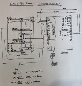 three.
My Reflection
Aside from the minor wiring error in circuit three, I completed my goal of successfully creating circuits without a hitch in the process. I will take 2/3 initial success’ as a positive and use that confidence moving forward. I also achieved my second goal of safety throughout the entire three circuit process. This was especially difficult to ensure in the building of circuit three with many wires, but my partner and I held each other to accountable levels of safety throughout. Something I learned from building circuit three was how to accordingly keep track of every wire and instrument placed onto the breadboard. Because all wires are different colors from that of the original diagram, it was difficult to keep track of so many, especially when they began to get clustered as more were inputed. So after the fact, I recognized that I need to create a checklist of all the required materials and check them off as I input them into the circuit. This will help in the future with organizational flow. I also learned from my mistakes last time and was more willing to ask for help this time which ended up aiding us to complete the third circuit on time.
Questions
- I define interaction as an inputed value with a corresponding output value. For example, when I swipe my metro card to enter an electronic gate, the gate opens as a result of my swiping my card. There was the input of the swipe, and the response was the gate opening. Examples are everywhere throughout our life without even realizing it. When I ask siri the weather, it responds and tells me it will be sunny in Shanghai today. My input of asking siri was met with an output response of siri telling me the weater. At its simplest form, interaction is output caused or triggered by an input. A similar example is when my partner and I Inputed a code for the correct pin number in the fade circuit, and the output was the corresponding fade of an LED. Thus, the LED faded, because we inputed code to do so. Where this gets interesting is when Igoe and O’Sullivan begin to introduce the concept of interaction. In their book Introduction to Physical Computing they quote a separate author, Chris Crawford, saying that interaction is defined as “an iterative process of listening, thinking or speaking between two or more actors.” (Intro to Physical Computing, Introduction XX). Although I agree with the principle of the definition, I want to disagree with the notion that an interaction is limited to these three actions. I think interaction carries a far broader set of categories which is why my own definition is a broad one itself. I did this on purpose to encompass much of what the world defines as interaction. However, Crawford is right to point out that interaction is between two OR more actors. I think this point is especially important to conveying the message that interaction isn’t just limited between two people. It can also be a chain of interaction stemming from machine to machine or person to person.
- The 10K resistor was used in coordination with the button to manage the amount of voltage available to it. Without a resistor, an unprescribed amount of power would be at the disposal of the button which would likely cause it to malfunction or overheat. The resistor simply acts as a buffer between the button and the power source of ground power to adjust the power to an appropriate amount.
- I would rearrange the LED lights in green and red to spell out the Chinese characters 欢迎来我的家 which directly translates to “welcome to my home” and place these on the front wall of my house. Likely during the holiday season to spread the cheer!
Sources Used
https://www.tinkercad.com/things/6MzvN5rlZlr-race-the-led-interaction-lab-ima
https://drive.google.com/file/d/1uviCK0V71cQpA76PV9PK03Df14vcsd0y/view (Igoe and O’Sullivan, Introduction to Physical Computing, introduction)
https://wp.nyu.edu/shanghai-ima-interaction-lab/category/recitations/
if you are trying to confuse me by giving the name of “Recitation One” to each of your recitation post, you almost got it 😛
the 10K resistor is used because otherwise you will be doing a shortcut every time you press the button. You can check out this video:
https://www.youtube.com/watch?v=RqI9MqVRB5A
Great documentation!
something I really like is that you are adding the sources at the end.