For this make-up recitation, unfortunately my partner has sicked and did not come to here, I finished everything on my own. So this recitation is for understanding basic sensors and trying to connect them with electronic components to see how it works.
I first chose the infrared distance sensor to make the circuit, but there is one point which is very important, there is a valid range on the packing bag of the sensor showing the rang it can measure precisely. For the sensor I use, the valid range range from 4cm to 30cm. So I come up with the idea that, I can use the sensor to detect how far my finger is from it, and by inputing the analog signal can control the brightness of a LED.
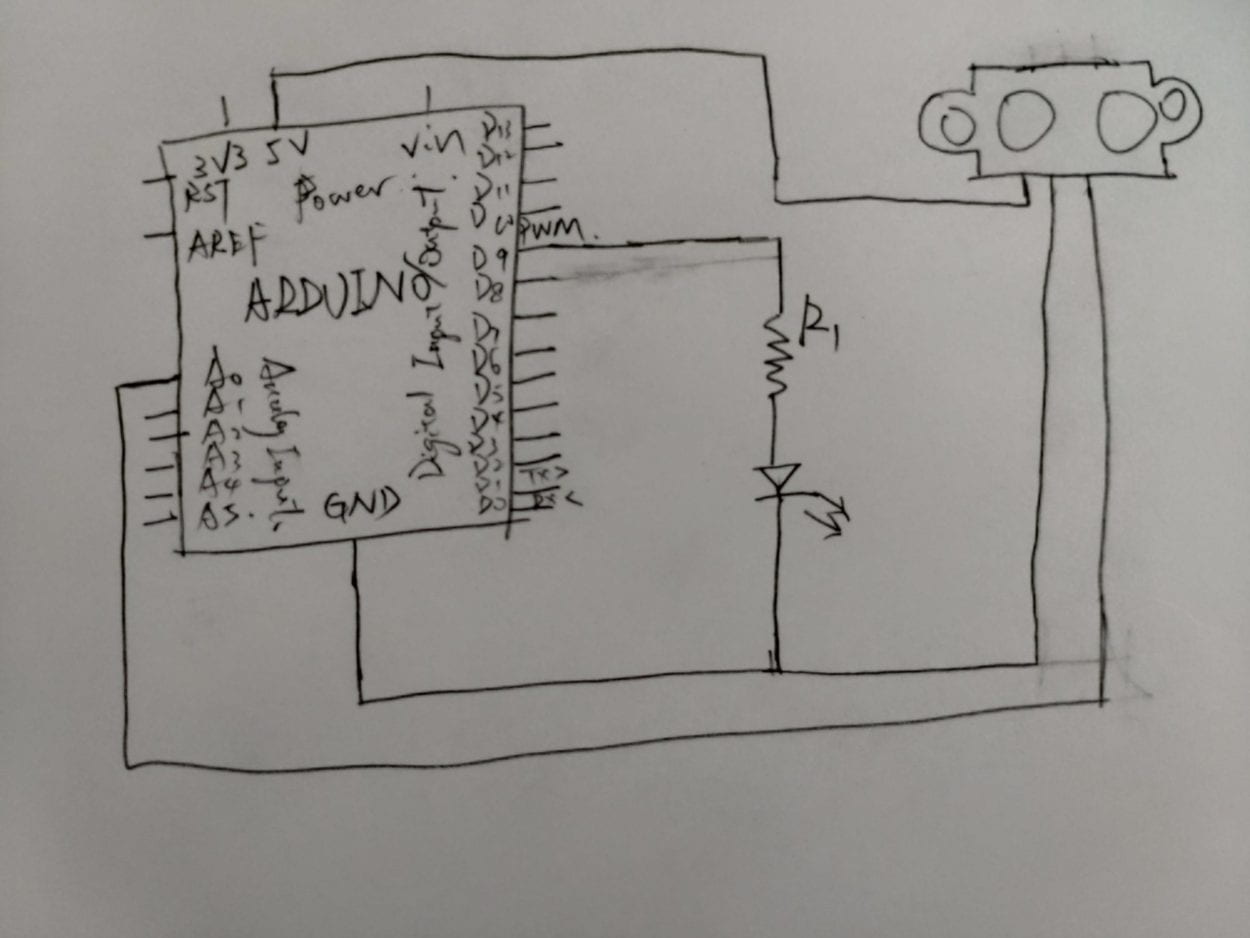
The following is my diagram for the circuit.
This is the arduino program
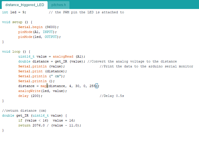
So I’m using pin A0 as the analog input, and pin D9 as the digital output, the resistor is for preventing the LED from overheating. I copy the code from the tutorial of how to get distance from the analog input, and I use map() to convert the valid distance into 0 to 255 to control the brightness of LED. I also set the delay to 200 as if the delay is too small, since the sensor is not that sensitive enough, the brightness of the LED will be very unstable.
The following is the result of the circuit.
As I finished the first circuit too fast, I got a joystick sensor to do a new one. I want to use a joystick to control four LEDs. I set the LED into a rhombus, when I pull the joystick upward, the LED on the top will be lighted up, when I pull to the left, the left one will shine, just like this. And when I press the joystick down, will all the LED shine.
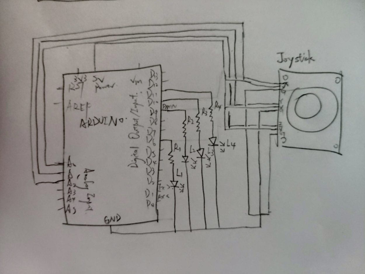
This the diagram I draw for the circuit, using three analog input to get the status of the joystick. The input is a three-dimensional coordinate, while x represents the horizontal position of the joystick, y represents the vertical one, and z represents how downward you press the joystick. The original coordinate is (512, 512, 512) and the coordinate ranges from 0 to 1024. I also connect four LEDs in parallel, each with a resisotr connected to it.
There are some error when the joystick is at the original state, so the value is not 512 but what is shown in the serial monitor, and when the joystick is pushed to the end, it might also be not that accurate so I set a range for it to make it easier to trigger the LED.
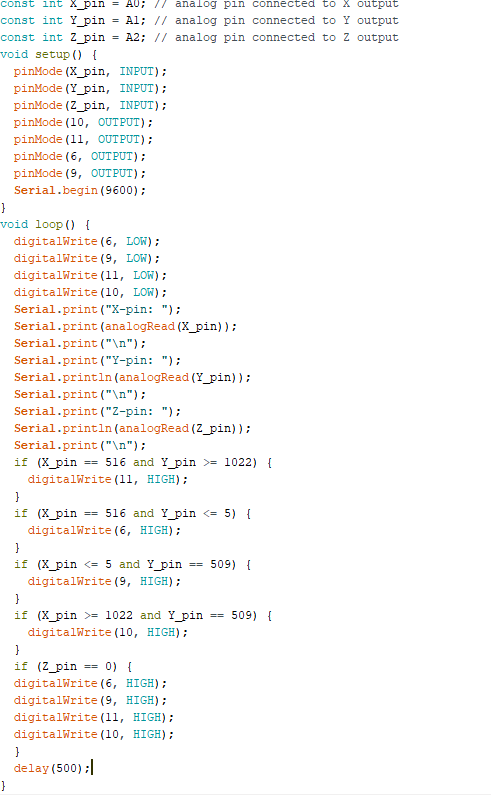
This is the code I write, and the result is in the following video which has failed. But I did not have time to check why it was wrong, was it because of the program or the circuit.
I think I will give it another try next time to find out where the problem is.