During our first recitation we were tasked to build three separate circuits and learn how to solder. I worked with Tian Tian and we were able to build the first two circuits however, we did have trouble building the third circuit.
Circuit 1
When we began we had to figure out which components we needed for each circuit. With the help of the appendix we were soon able to figure out which items we needed and what their purpose was. We got our items and with help from the learning assistants we began building our circuit. We pulled out the breadboard and connected it to the voltage regulator which we learnt was used to maintain constant voltage. We quickly learnt that electricity flows from positive to negative on the breadboard.
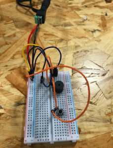
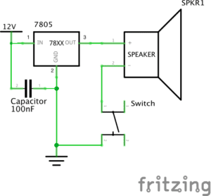
We began with the red wire from the multimeter and connected it to the positive input on the breadboard. We then took a jumper cable and connected it to the capacitor which we learnt was used to store energy and electric charge. We also had to figure out how to place the voltage regulator properly. We referenced back to the diagram in the appendix and learnt that the middle ‘prong’ always had to go back to ground, the first ‘prong’ to the input and the third prong to the ‘output’. The speaker and switch were pretty easy to connect to, however we did have to keep in mind the four legs of the push button switch (A,B,C,D) and the right positions to place them in. The more we worked on the circuit the more familiar we got with the various instruments and their roles.
Circuit 2
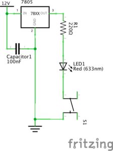
For the next circuit we followed the same steps we had followed with circuit 1. What was different in this circuit was that we were now required to include an LED. In inserting an LED I also learnt we had to insert a 220 Ohm resistor in order to control the amount of current flowing into the LED. We struggled a bit with attaching the resistor and LED into the correct positions on the breadboard. We had to keep in mind the direction of the flow of electricity and once we familiarized ourselves with this we were able to attach all the components and light up the LED! (In the picture below we struggled with placing the resistor as we were at first not sure whether it had to be placed before the LED or after and in what positions with relation to each other.)

Circuit 3
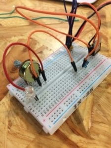
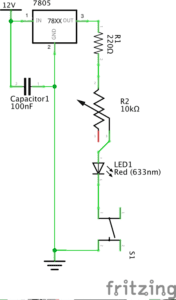
For circuit three we followed the same instructions for circuit 1 and 2. The new object here was the Variable resistor also known as the Potentiometer. We learnt that the variable resistor/ potentiometer was used to control or adjust currents and so when attached to the breadboard, we would be able to “dim” the LED . Connecting that was a bit confusing at first but we later saw we had a broken potentiometer and replaced it. However it still did not work and we figured it was because we had not soldered the wires properly. We recorded a video of us breaking our process down step by step to help us in the future and know how we could have better built our circuits.
Question 1:
With relation to the reading Art of Interactive Design, I was reminded of the process of human interaction and conversation that the writer refers to when defining interactivity. In a conversation, each participant has to listen, think and then speak and I saw a similar process here when building the circuits whereby the input (electricity) was the “listening process” and the output such as the LED lighting up or sound coming from the buzzer was the “speaking” process.
Question 2:
Zack Lieberman in his video uses interactive design and physical computing to make art come alive. One of the ways he does this is through an open source eye tracking system that he uses to help disable artists draw by using their eyes. In this way art goes beyond the ‘paint on a canvas’ module that we all know to a more technologically advanced and interactive way of bringing life to art.