Here we are! The first interaction lab recitation! In this week, me and my partner were required to build up three circuits on the breadboard and solder one button. It had been a great experience since I achieved all the requirements and even had a little bit modification on the circuits. Here am I documenting my process.
Materials:
- 1 * Breadboard
- 1 * LM7805 Voltage Regulator
- 1 * Buzzer
- 1 * Push-Button Switch
- 1 * Arcade Button
- 1 * 220 ohm Resistor
- 1 * 10K ohm Resistor
- 1 * 10K ohm Variable Resistor (Potentiometer)
- 1 * LED
- 1 * 100 nF (0.1uF) Capacitor
- 1 * 12 volt power supply
- 1 * Barrel Jack
- 1 * Multimeter
- Several Jumper Cables (Hook-up Wires)
Circuit 1:

This circuit functions as a simple speaker. Though the circuit looks pretty straight forward, yet the actual work on the breadboard wasn’t going all well. We were wrong about how the pins inside the breadboard were wired. I thought all the pins in a column were connected, then discovered the middle part was horizontally connected. And it has been quite a long time for both me and my partner to build a circuit, thus it took quited some time to fix the bugs and finish the circuit. Finally, we managed to get it worked!
Circuit 1. Test Video
Circuit 2:

Similar as the first circuit, this one works as a small light. The difference is that, the led light is polarized, which only allows the current to flow one side to another. Also, the led light only takes about 2~3 volts. Simply plugging it into the 12V DC power would blow it. So another 220 Ω resistance is needed. With the experience of the first one, we immediatedly got this one working.
Circuit 2. Test Video
Circuit 3:

This is the improved verison of circuit 2, which adds a dimmer switch to the led light. The key is to figure out how to connect a potentiometer, which has three pins, into the circuit. We looked at the diagram and followed the instructions.
Circuit 3. Test Video
Soldering: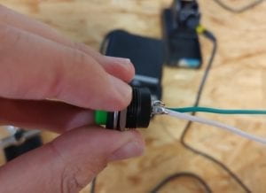
This bit was to solder two wire onto the button switch. It was actually a part that require manual skills. Thanks to my previous experience in soldering, I got in the state of working quickly. I cut the wire, peeled off the skin, and wired through the little holes on the button and bent the end over so that it would not easily fall off in the soldering process. The next step was to clip the button on to the bracket, heat up the soldering iron and get to work! I put the tin wire onto the bit where the copper wire and the button touches, and used the soldering iron to heat up the tin. When the tin melts, I used the tip of the soldering iron to spread out the tin liquid so that the metal bits can be firmly welded, and also to lower the resistance. I soldered the white wire, and then got to help my partner with the green wire. Finally, both wire were firmly fixed, and the button was functioning well.
Playtime:
Having done all the tasks, my partner and I started to create something with the materials in hand. We discovered that the 220 Ω resistance, which was used to protect the led light, was within the range of the 10 K Ω potentiometer. So we wondered whether we could only use the potentiometer and add the speaker into the circuit. With the idea going, we set to work. We wired the speaker (and the new button switch) in, and adjusted the potentiometer to its maximum resistance in case the current might blow the led light. Then we gradually lowered the resistance, until both light and speaker works properly. In this way, a simple Morse code machine was created! We tested with a simple signal SOS (… — …), and all the components were working just fine. This gave us endless fun.
Reading Questions:
- I think our circuits are interactive because on the most basic level, these circuits are respoding to my input. They beep, or light up when I press the switch. The light dims or lights when I adjust the potentiometer. I give it an input, it provides an output. In this way, an interaction cycle is completed.
- Interactive Art can be seen as a combination of Interactive Design and Physical Computing. As the interactive painting example shown in Zack Lieberman’s video. The user poses an input, then computer processes the input, and gives an output by changing the position of the painting accordingly on the screen. Thus this art piece is created by an interaction cycle, i.e. input-process-output.
Good job