For this week’s classes and recitation, I learned and practiced how to use a breadboard to build a working circuit. My partner and I complete three model circuits during the recitation. We encountered some problems. But we figured them out and successfully made the circuits work in the end. The documentation of how we build the circuits are as follows. We built Circuit 2 first, then Circuit 1, and Circuit 3 the last.
Circuit 2:
Introduction
This circuit is built to work as a lamp. When pressing the bottom, it is supposed to light
Components
-
- 1 * Breadboard: to connect the components together.
- 1 * LM7805 Voltage Regulator: to make power works and current stable.
- 1 * 100 nF (0.1uF) Capacitor: to make the current stable
- 1 * Push-Button Switch: turn the lamp on and off
- 1 * 12-volt power supply: make sure the power works
- 1 * Barrel Jack: make power works
- Several Jumper Cables (Hook-up Wires): link components on the breadboard together.
- 1 * LED: used as a lamp that can light
- 1 * 220-ohm Resistor: resist the current to ensure safety
- 1 * Multimeter: to test the circuit and find the mistake
Design and outcomes
-
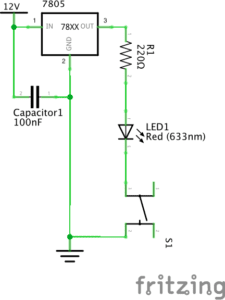
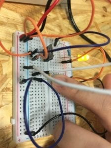
- Following the instructions, we link these components like this.

-
- And it works

Building process
Since I have experience working on circuits and am familiar with how the breadboard works, our group does not have a problem building the circuit. However, we met with a few problems that make the circuit does not work in the beginning.
Problem 1: For the Voltage Regulator, we do not know which one is “in” and which one is “out.”
Solution: We tried to link them to power and see which one works.
Problem 2: The light is not on when the circuit is closed.
Solution: We used a multimeter to test the voltage between different parts of the circuit. Finally, we found out that we did not link the GND back to the negative electrode of the power.
Problem 3: The switch does not work. The LED is always on.
Solution: By using a multimeter to test the different sides of the switch, we found out that every two sides of this kind of switch are linked together. After understanding this mechanism, we turned the switch 90 degrees. It finally works.
Circuit 1:
Introduction
This circuit is built to work as a doorbell. When pressing the bottom, it is supposed to ring.
Components
-
- 1 * Breadboard: to connect the components together.
- 1 * LM7805 Voltage Regulator: to make power works and current stable.
- 1 * Buzzer: to make sound
- 1 * 100 nF (0.1uF) Capacitor: to make the current stable
- 1 * Push-Button Switch: turn the doorbell on and off
- 1 * 12-volt power supply: make sure the power works
- 1 * Barrel Jack: make power works
- Several Jumper Cables (Hook-up Wires): link components on the breadboard together.
Design and outcomes
-
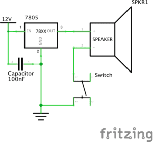
- Following the instructions, we link these components like this.

-
- And it works
Building process
On the basis of Circuit 2, we took out the LED and the resistor and replace them with buzzer. It works.
Circuit 3:
Introduction
This circuit is built to work as a Dimmable Lamp. We can turn the LED to different degrees of lightness.
Components:
besides what we have in Circuit 2, there are:
-
- 1 * 10K ohm Variable Resistor (Potentiometer): to adjust the lightness of LED by turning the resistor to different ohm.
- 1 * Arcade Button: another kind of switch.
Design and outcomes
-
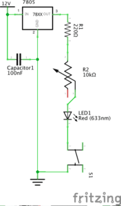
- Following the instructions, we link these components like this.

-
- And it works
Building process
On the basis of Circuit 2, we add a variable resistor into the circuit. Again, we do not know to link it into the circuit. We tried different ways and figured out the correct one. Afterward, we change the switch to the Arcade button. It works.
Reading question 1:
According to “What Exactly is Interactivity?” the author thinks that interactivity requires “input, process, and output” (5) and “it responds to … reactions” (6). All three circuits meet these requirements. Let’s use “doorbell” as an example. One person presses the button, giving the information that “I’m waiting outside the door,” is “input.” Then the circuit close, meaning that it gets the information and do “process” on it. As a result, the bell rings as an “output.” Furthermore, as what the author means on “interactivity,” these circuits also function to entertain the users. At least, I think it’s quite interesting to press the button and make the doorbell rings with certain beats no matter whether this “interactivity” is “subjective” or not.
Reading question 2:
According to the three projects that Zack Lieberman introduces, we can see that these projects perfectly applies his interaction design to Interactive Art by using physical computing. So, I would argue that “physical computing” is one essential approach to make an interactive idea come into interactive experiences that work in the real world. “EyeWriter” is one example. The software and hardware, regarding as “physical computing,” makes it possible for disabled to create work in a creative way. These technologies are the key to making the design of this project works. Without “physical computing,” it could only be an ideal model instead of existing art that can interact with people.
Works Cited
Crawford, “The Art of Interactive Design,” pp. 1-5.
Lieberman, Zach, “Zach Lieberman: Interactive Art,” PopTech, 2010.