Overview:
In recitation 1, we soldered one arcade button and built three circuits in pairs. I completed the whole work with my partner, Cindy.
Material:
- Breadboard
- 1 * LM7805 Voltage Regulator
- 1 * Buzzer
- 1 * Push-Button Switch
- 1 * Arcade Button
- 1 * 220 ohm Resistor
- 1 * 10K ohm Resistor
- 1 * 10K ohm Variable Resistor (Potentiometer)
- 1 * LED
- 1 * 100 nF (0.1uF) Capacitor
- 1 * 12 volt power supply
- 1 * Barrel Jack
- 1 * Multimeter
- Several Jumper Cables (Hook-up Wires)
Soldering:
After listening to a brief introduction of today’s tasks and picking up the materials, we were led to 826 to connect the button with wires using solders and soldering irons. The iron can only be used after it is heated to 300-350 celsius degrees, so it is really important to take care of yourself. Solders were melted on the iron and then stuck to the connecting part on the button. Electricity can then go through the wires. It took a few minutes for us to finish soldering as the iron needed more than thirty seconds to heat.
It was hard to solder in beautiful shape and the stick was stuck on the button for a second.
Building circuits:
With our partners, we started to build three circuits: a doorbell, a lamp, and a dimmable lamp.
Circuit 1: Door Bell
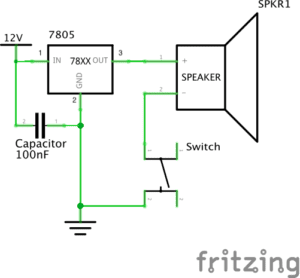
It took us the whole class to deal with the first circuit since we could not even understand the relationship between the diagrams (schematics) and the real circuits. How those components should be connected was the biggest problem we met during the process.
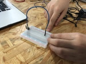
At first, we figured out the meaning of each diagram for the components. It wasn’t hard until we really started making it. We tried to do it by ourselves for the first time, but the bell just didn’t ring. We turned to TAs for help, and she pointed out three problems inside our circuits. First, we misunderstood the breadboard. The bar on the side writing “+” and “-” was where the power should be connected to. Also, the left part and the right part was disconnected even if the blocks were on the same row. Second, the wires connected were too messy that we could hardly see what was wrong inside of the circuit. Third, “1” written on the schematics did not mean that the “1” on the speaker needed to be connected to “1” on the regulator. It was just how many connecting ports the components had.
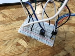 This was what we first got.
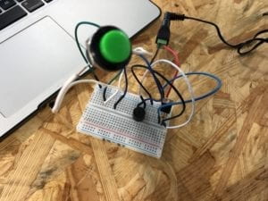 This was the adjusted, correct, final version.
Circuit 2: Lamp
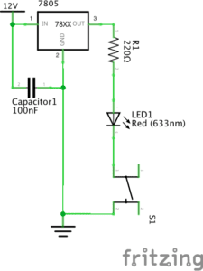
The lamp one is almost the same as the doorbell. You only need to replace the doorbell with the light and add a resistor connected with the LED light. The final work of a lamp circuit.
Circuit 3: Dimmable Lamp
Replace the resistor by the variable one. The final work of a dimmable lamp circuit.
Reflection:
I understood the meaning of schematics and the diagrams of components. Also, I learned how to use the soldering iron and solderless breadboard. Knowing how to build a circuit is necessary for future creations.
Question 1: After reading The Art of Interactive Design, in what way do you think that the circuits you built today include interactivity? Please explain your answer.
In the reading The Art Of Interactive Design, interaction is defined as a cyclic process in which two actors alternately listen, think, and speak. All the circuits built in the first recitation are interactive as they can respond by lighting up, or making sound when I push the button.
Question 2: How can Interaction Design and Physical Computing be used to create Interactive Art? You can reference Zack Lieberman’s video or any other artist that you know .
Interaction design is the basic of the interactive art. What the artist believes in influences his/her interaction design, and shape the final product which the artist wants to use to convey her beliefs to the audience. At the same time, physical computing is the way leads to an interative project, just like how we build the circuits. The “buttons” used in more complex works are often the monitors or sensors, which can “listen, think”, and evetually respond–“speak”. The project “drawn” brought by Lieberman can prove it as it has the basic design–deeper messages to convey, and the physical computing–the monitoring of motions.
this is a very good documentation post Jiahui!