For our first recitation, our task was to build three circuits with basic knowledge of how breadboards, resistors, and LEDs work. To build them, we used:
- 1 Breadboard
- 1 LM7805 Voltage Regulator
- 1 Buzzer
- 1 Push-Button Switch
- 1 Arcade Button
- 1 220 ohm Resistor
- 1 LED
- 1 100 nF (0.1uF) Capacitor
- 1 10K ohm Variable Resistor (Potentiometer)
- 1 12 volt power supply
- 1 Barrel Jack
- 1 Multimeter
- Several Jumper Cables (Hook-up Wires)
Circuit 1
My partner and I, having no prior experience with hardware, went into making the first circuit a bit blind. We were confused about how the circuit map translated onto the breadboard, which I thought would physically be a similar layout as seen in the image. However, Katie came over to help us have a clear idea of how to read the circuit map. She explained that the breadboard would look much different than the picture, and that the picture was only a guide of how to connect the elements with the cables. She told us to start at the 12V power, where we should plug in power and ground into the side of the breadboard. Then working our way outwards, we connected the voltage regulator that maintains a constant voltage level to the speaker which emits a high pitched sound. Katie gave us a hint of how to place the switch that triggers the speaker over the gap in the middle of the breadboard, and to put the capacitor that stores electrical energy in between the power and voltage regulator. Once plugged into power, we pressed the switch and heard the high pitch from the speaker, indicating success! 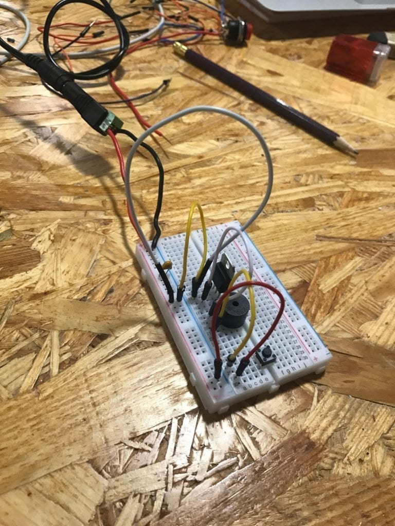
Circuit 2
After getting the rundown from Katie of how to read the circuit map and build onto the breadboard, constructing the second circuit was a lot simpler. Most of the positioning on the breadboard was similar to Circuit 1, but instead of the speaker, we added in the resistor that reduced current flow and the LED light, paying attention to the LED’s polarity. When we pressed the switch, the LED lit up, making it another successful circuit. 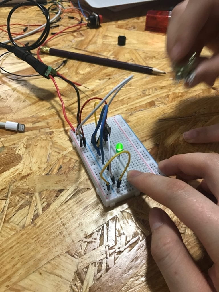
Circuit 3
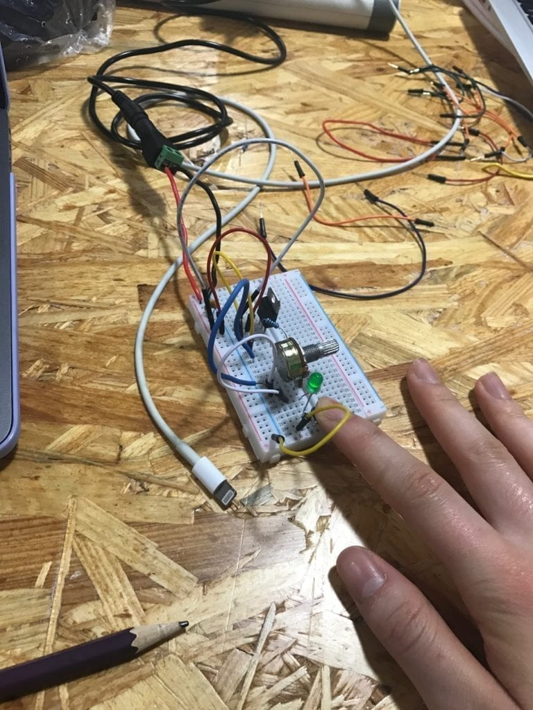
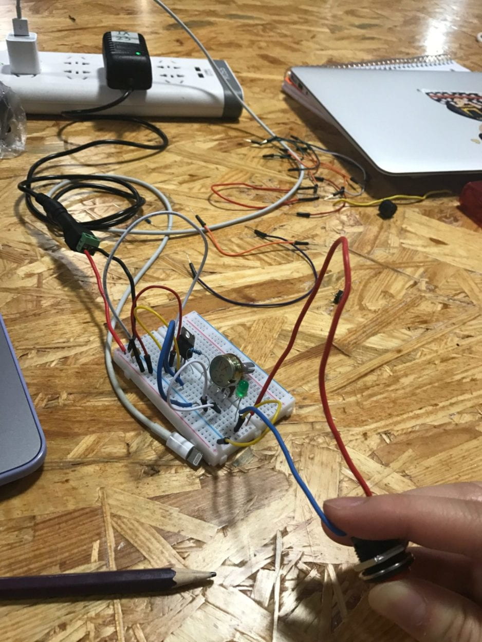
We gained confidence for the last circuit, since it only required adding a variable resistor to dim the LED on Circuit 2. However, we ran into trouble with reading the circuit map, since the symbol included an unconnected arrow. We fumbled around with trying to connect the variable resistor, unsure of where the connections needed to go. Katie helped us read the map and figure out that one of the three prongs on the resistor didn’t need a connection. Nevertheless, it was still a bit hard making sense of the wire-ridden board and which connections still had to be made, since we built on the previous circuit, not from scratch. Because of this, we didn’t properly connect the LED, so when we tried to run the circuit, nothing happened. Young then came around to help us figure out what was wrong, pointing out that our LED wasn’t put in the right place yet. After his help, we were able to get the light to turn on and dim with the variable resistor. Finally, we replaced the switch with the button we soldered and got it to work as well.
Question 1
The circuits built have interactivity because there are two actors that respond to each other. One actor is the finger that pushes the button, and the other actor is the speaker that emits sound or the LED that turns on. Without the finger, the speaker or LED will not turn on. In turn, the person pushing the button reacts to the speaker or LED, removing the finger when they do not want the element to be on anymore. Thus, the two actors behave in response to one another, just like the refrigerator light and the person opening the door in “The Art of Interactive Design.” This interactivity is extremely simple, so it is a “low” degree of interactivity, as mentioned in the reading.
Question 2
Interaction design and physical computing can be used hand in hand to bring a piece of art alive. Traditionally, you walk into a museum and admire paintings from a three foot distance, unable to get close to touch or feel the art in front of you. However, with new technology, art pieces can be used to respond to the viewer, creating more memorable experiences with art. For example, Netflix’s new interactive movie, “Bandersnatch,” gives viewers options within the storyline so that they are directly involved with how the movie ends. Different options lead the story in extremely different directions, which required the makers to film scenes over and over again, with slight iterations for different choices. Additionally, a science museum in San Francisco called the Exploratorium has a piece in which people stand in front of a projector, which projects multiple multi-colored shadows onto the wall behind the people. They are able to create fleeting art pieces with their bodies, which makes it one of the most popular exhibits in the museum.