Recitation Date: 2/15/19
Instructor: Marcela Godoy
Circuit 1: Door Bell
Materials:
1 * Breadboard, 1 * Buzzer, 1 * LM7805 Voltage Regulator, 1 * Push-Button Switch, 1 * 100 nF (0.1uF) Capacitor, 1 * 12 volt power supply, 1 * Multimeter, Several Jumper Cables (Hook-up Wires), 1 * Barrel Jack
At first, we had no idea how to use the breadboard. So instead of using it, we tried to connect each component directly with the wires and quickly realized that was a mistake. With the help of some fellows, we were given a quick rundown on how to use the breadboard.
When the circuit was first completed, it did not work because the voltage regulator was not properly connected to the speaker and capacitor. We only connected one wire from the regulator to the voltage, and tried to connect the regulator with the speaker and capacitor without wires.
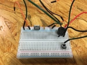
After finally fully grasping how to use wires and the breadboard, the circuit was properly completed. Although the speaker did go off, the switch did not work. When we pressed the switch, it couldn’t turn the speaker on and off like it should. So after some close inspection and help from the fellows, we noticed that the switch was not put in correctly. After that was solved, the switch finally worked.
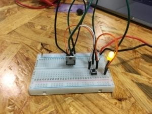
Circuit 2: Lamp
Materials:
1 * Arcade Button, 1 * 220 ohm1 * Breadboard, 1 * LM7805 Voltage Regulator, 1 * Push-Button Switch, 1 * 100 nF (0.1uF) Capacitor, 1 * 12 volt power supply, 1 * Multimeter, Several Jumper Cables (Hook-up Wires), 1 * Barrel Jack
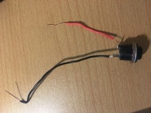
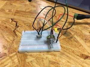
This time, building the circuit went smoothly. Before constructing the circuit though, we tested to see which resistor had 220 Ohms with the multimeter. After we built the circuit, we tested it but the LED didn’t light up so we double checked all the wires and position of the components. It turned out that the LED light was not put in correctly. The positive and negative was put in the other way around. After we fixed that, the LED lighted up and the switch also worked. For this circuit, we tried replacing the switch with the arcade button we soldered and that also went smoothly.
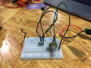
Circuit 3: Dimmable Lamp
Materials:
1 * Arcade Button, 1 * 220 ohm1 * Breadboard, 1 * LM7805 Voltage Regulator, 1 * Push-Button Switch, 1 * 100 nF (0.1uF) Capacitor, 1 * 12 volt power supply, 1 * Multimeter, Several Jumper Cables (Hook-up Wires), 1 * Barrel Jack, 1 * 10K ohm Variable Resistor (Potentiometer)
By now, we had no problem putting together the circuit. We tested how the dimness of the LED light would change if we plugged the wire into the different parts of the variable resistor. We found out that the dimness level actually changes.
Reading Response:
The circuits that we built during recitation included interactivity because the LED light gave feedback when we pressed the button. However, as mentioned in “The Art of Interactive Design” feedback from machines like a light lighting up in a fridge or from the LED light in our case, is an example of a low level of interactivity. The circuit with the highest interactivity would probably be the last circuit where we were able to change the level of dimness by plugging the wire into different parts that were connected to the variable resistor.
Interaction design and physical computing can act as tools to create interactive art. The product that Zack Lieberman created the EyeWriter which enables Tony, a graffiti writer, who is paralyzed to be able to write graffiti with just his eye. The Eyewriter allows Tony to once again be able to interact with his environment by writing graffiti. This just shows that physical computing can create tools that allow humans to interact with their surrounding.