Name: Yuru Chen(Lindsay)
Lab Date: 15 February 2019
Instructor: Marcela Godoy
Lab Partner: Skyler Liu
Aim: For today’s recitation, we are going to pair up and 1)get to know how to use all the components given by the instructor, 2)learn how to build a circuit with these components.
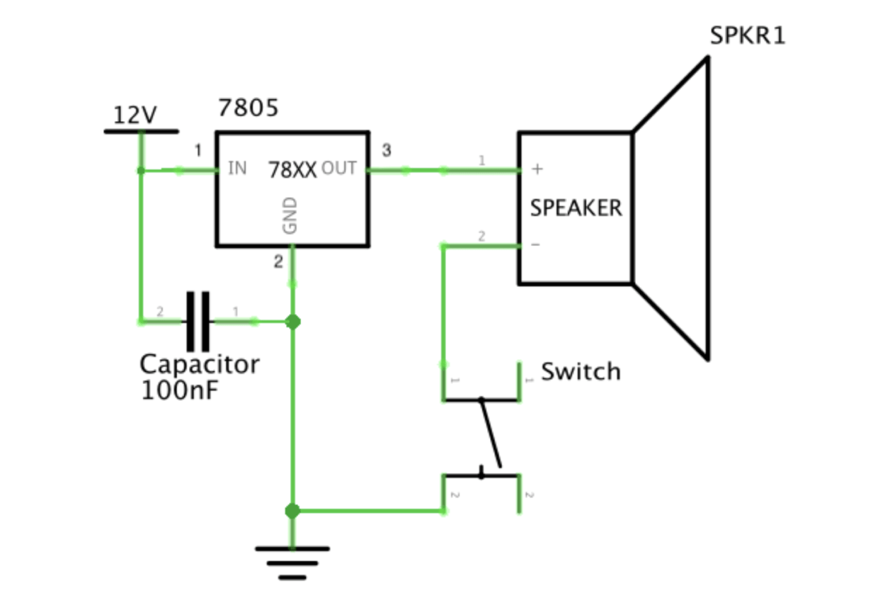
Circuit 1: Door Bell
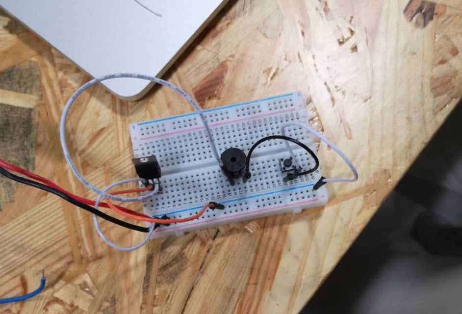
For this circuit, we used the following components:
- Breadboard⇒A board that has metals lay at the bottom of it and connect the holes above. A breadboard is used for connecting the components and organizing the circuit.
- LM7805 Voltage Regulator⇒It takes 12 volts from the power and generates 5 volts as output for the speaker to work effectively.
- Buzzer⇒This component is here because it is used as a speaker. Once the circuit works it will make a sound.
- Push-Button Switch⇒The switch is used as a input and once you switch on the current can pass through it.
- 100 nF (0.1uF) Capacitor⇒This component is used to store the energy and give out the energy again when necessary, which is when you switch on and the current flows in the circuit.
- Several Jumper Cables (Hook-up Wires)⇒Those wires are used to connect other components to the breadboard and for the current to flow through it.
This Door Bell circuit works at the end. However, we have encountered some failure during the process. At the beginning we didn’t know how to connect each of the wires correctly, as a result, it didn’t work. So later we revisited the circuit, checked if the current can pass through each components freely. We realized that we didn’t really understand how to use the breadboard to make the current flow, which led to the failure of our first try. Fortunately, we finally figured it out and made it work.
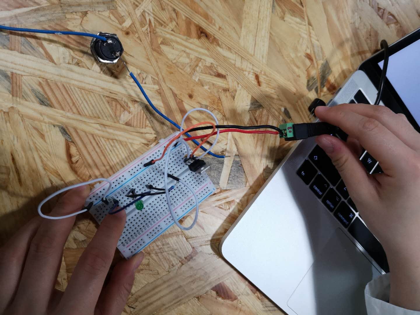
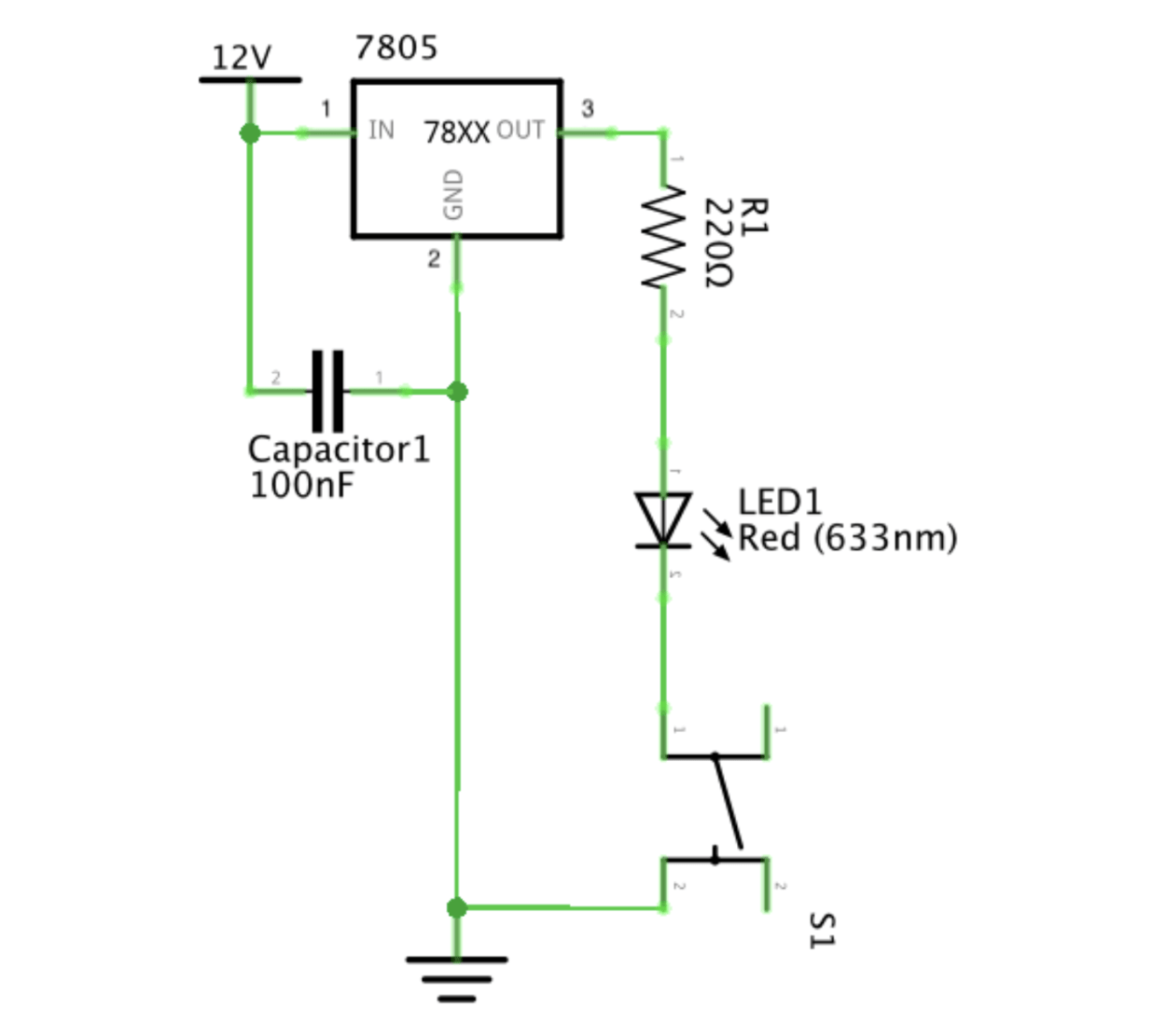
Circuit 2: Lamp
For this circuit, we used the following components:
- LM7805 Voltage Regulator⇒It takes 12 volts from the power and generates 5 volts as output for the speaker to work effectively.
- 220 ohm Resistor⇒This is used to reduce the current flow and to reduce the voltages run in the circuit. We used this component here because it can reduce the current flow in this LAMP circuit to give the voltage needed for the LED to work.
- LED⇒This component is used as an output and it will be lighted up when the circuit works.
- Push-Button Switch⇒The switch is used as a input and once you switch on the current can pass through it.
- 100 nF (0.1uF) Capacitor⇒This component is used to store the energy and give out the energy again when necessary, which is when you switch on and the current flows in the circuit.
- Several Jumper Cables (Hook-up Wires)⇒Those wires are used to connect other components to the breadboard and for the current to flow through it.
After we completed the first circuit, there was no difficulty for us to built the second one. All we need to do was to move the speaker out of the circuit and replace it with the resistor and LED. We paid close attention to how to connect all these components with each other, and the circuit worked really well at the end.
Circuit 3: Dimmable Lamp
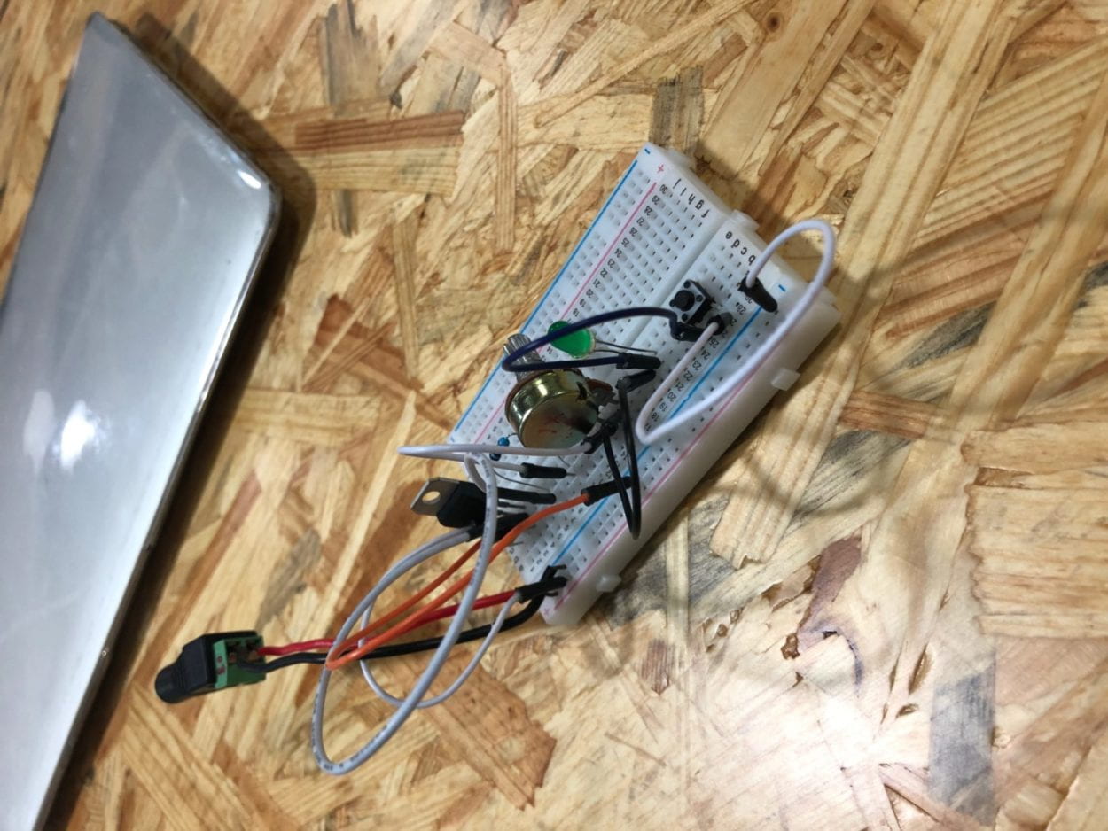
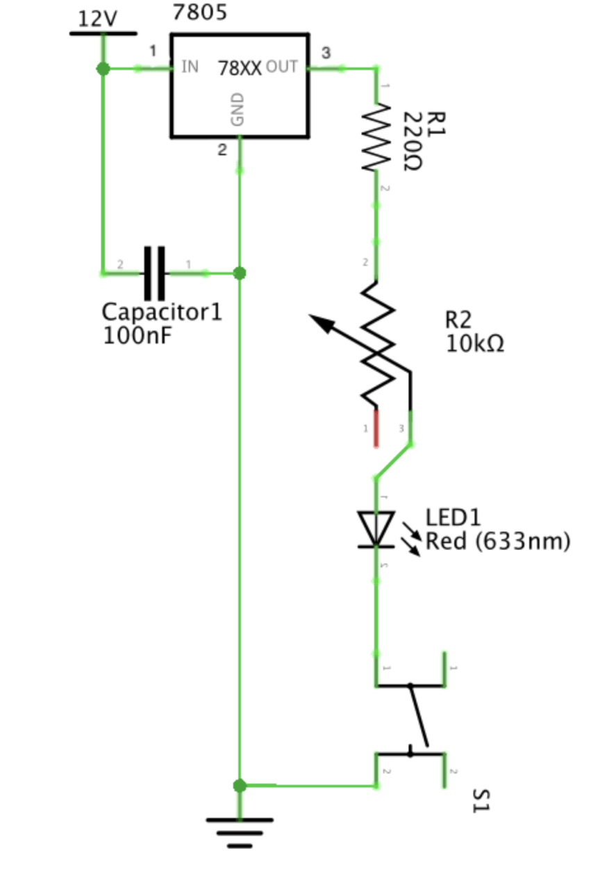
For this circuit we used the following components:
- LM7805 Voltage Regulator⇒It takes 12 volts from the power and generates 5 volts as output for the speaker to work effectively.
- 220 ohm Resistor⇒This is used to reduce the current flow and to reduce the voltages run in the circuit. We used this component here because it can reduce the current flow in this LAMP circuit to give the voltage needed for the LED to work.
- 10K ohm Variable Resistor (Potentiometer)⇒This component is used to control the voltages run in the circuit and thus can control the brightness of the LED.
- LED⇒This component is used as an output and it will be lighted up when the circuit works.
- Push-Button Switch⇒The switch is used as a input and once you switch on the current can pass through it.
- 100 nF (0.1uF) Capacitor⇒This component is used to store the energy and give out the energy again when necessary, which is when you switch on and the current flows in the circuit.
- Several Jumper Cables (Hook-up Wires)⇒Those wires are used to connect other components to the breadboard and for the current to flow through it.
For this circuit, we followed the previous steps of replacing one component with other ones. Here we only need to add one more component to the previous LAMP one, which is the variable resistor. So we first inserted the variable resistor in the breadboard, then we linked the wire which was previously connected with the LED to the first leg of the variable resistor. Then we linked the second leg of this variable resistor to the resistor, which was the one also in the previous circuit. Then we connect the power. It works perfectly.
Problems:
In our group, the only problem me and Skyler have encountered, which was stated in the process for the first circuit, was that we didn’t know how to make the current flow freely in the breadboard, namely we didn’t know how the breadboard work. However, after struggling by ourselves for a while we decided to ask one of the learning assistants. She explained how the circuit works and helped us check which part of our circuit went wrong.
Answers to the Questions:
- I think the circuit I built today includes interactivity in the way I interact with it. In the three circuits I built today, I need to press the button(switch) to make the circuit work. First, during the process of building the circuits, I think. I think about how to connect the wires and the components to make it work. Without me interact with those components(for example, press the button of the switch) the circuit wouldn’t have worked. In this way, I think the circuit I built today includes interactivity.
- In Zach Lieberman’s video, some interactive artists create interactive arts by combining the interaction design and physical computing. For example, in his video, he mentioned that there is an artist “drawing” a bottle of wine and a glass on a whiteboard, and then take them out as two real objects. This artist use a projector to project the glass the wine on the board, which is a interaction design. And then he uses his physical movement to pretend he is drawing. This is a interactive art created by combining the interaction design and physical computing.