Materials and functions:
- 1 * Breadboard Provide a base for making electronic connections and aid in the prototyping of circuits.
- 1 * LM7805 Voltage Regulator Maintain a constant voltage level. Make the output voltage 5V for other components to work safely.
- 1 * Buzzer An audio signaling device.We can tell if the circuit works by listening to it.
- 1 * Push-Button Switch Be used to interrupt the flow of current through a circuit. We use it to control(turn on/off) the buzz and the LED.
- 1 * Arcade Button Be used to interrupt the flow of current through a circuit. We use it in soldering. Actually it’s an alternative of push-button switch.
- 1 * 220 ohm Resistor Resist the flow of electricity to control the flow of current. It protects the LED from burning out.
- 1 * LED A visible light source. We can tell if the circuit works by looking at it.
- 1 * 100 nF (0.1uF) Capacitor Store electricity while current is flowing into them, then release the energy when the incoming current is removed. (Question: I still don’t know why it is included in circuits and in parallel with other loads)
- 1 * 10K ohm Variable Resistor (Potentiometer) A resistor whose resistance can be adjusted. We use it to change the degree of LED brightness.
- 1 * 12 volt power supply Provide the power for other components to work. It( 12V DC) was translated from 220V AC and then to 5V DC.
- 1 * Barrel Jack It connects the power supply with the breadboard.
- 1 * Multimeter Be able to measure the electrical properties of voltage, current and resistance. They are useful for testing circuits and determine the cause of electrical problems within a circuit. We use it to measure the resistance to find a 220 ohm resistor out of others.
- Several Jumper Cables (Hook-up Wires) Be used to carry electricity from one point to another. We use it to connect different electrical components.
Tasks
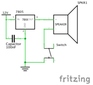
- Circuit 1
diagram
video
process
Actually, this was my first time to build a circuit, although I had previewed some readings, I still got confused at first. So did my partner Sarah. So she asked a teaching fellow for help. The fellow almost helped us through the whole course. The first problem we confronted is about the resistors . We measured several resistors with the multimeter. But their resistance were all 10 ohm. At last we found one 220- ohm resistor with the help of the fellow.
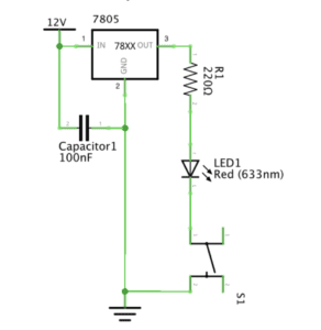
- Circuit 2
diagram
video
process
In this task, we added a new component: switch. But after we finished building the circuit and pressed the button on the switch, it didn’t work because the LED was always on. With the help of the teaching fellow we found out that we actually put the switch in the wrong place, so it was always connected. Later we put it across the middle line of the breadboard.
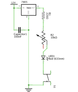
- Circuit 3
diagram
video
process
We built this circuit quite successfully and smoothly, just by adding a potentiometer on the basis of task two.
- Soldering
picture
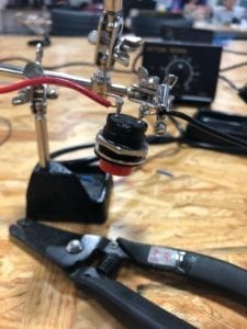
process
My partner Sarah tried to solder the Arcade Button with the red electric wire first, and the teaching fellow( another) emphasized that we should use the side of the tip of the iron instead of the very tip and scratch the soldering iron in the box when that part turns dim. But when I tired to solder the Arcade Button with the black electric wire, it still turned to be difficult to feed the melting roll of solder into the contact point. Anyway, I made it.
Answers to questions:
1. In “The Art of Interactive Design”, the author generalizes the notion of the conversation as an interactive process to any human interaction and condensed it to three steps: listen, think, and speak (in turn). Academically, it’s input, process and output. From my perspective, the circuits we built do include interactivity because they can respond to our deeds like clicking the button of switch and changing the resistance of potentiometer by turning on and off the buzz/LED and changing the degree of LED brightness. But it’s also of low interactivity like the example of refrigerator light given by the author.
2. In Zach Lieberman’s video, the most impressive project for me is EyeWriter designed for paralyzed graffiti writer Tony. Their team created low-cost eye-tracking softwares and hardwares( connecting IR LEDs, micro CCD CAM, etc to sunglasses with copper wires and wire ties ), the result was quite pleasant that Tony could write graffiti and polish his works with his eyeballs, and his graffiti was even shadowed to the building.In my opinion, Interaction Design is the inner inspiration and Physical Computing is the technical basis for the design to be operated successfully. Interactive Art is created by the combination of the two.
Reference list:
Class 02 / Feb 14 Thu / Electricity, Electrical Components & Circuits