Lab Date: Feb 15, 2019
Instructor: Marcela
Lab Partner: Sam Li
Aim of Today’s Lab: build three sets of circuits using the breadboard and learn how to solder.
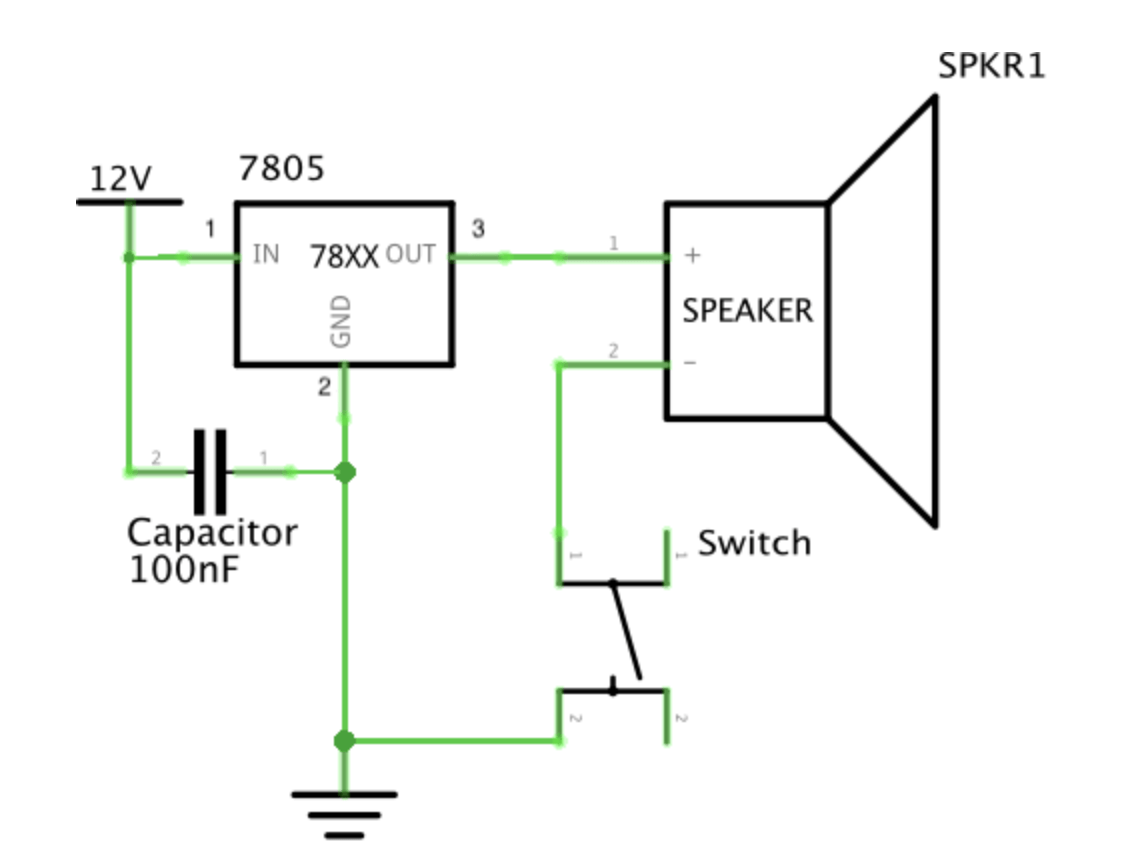
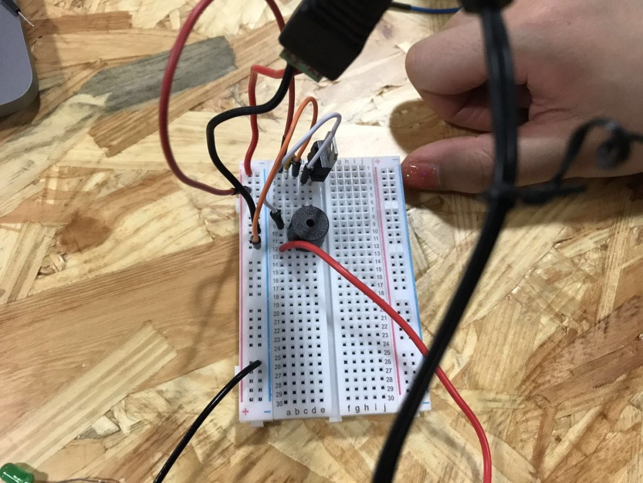
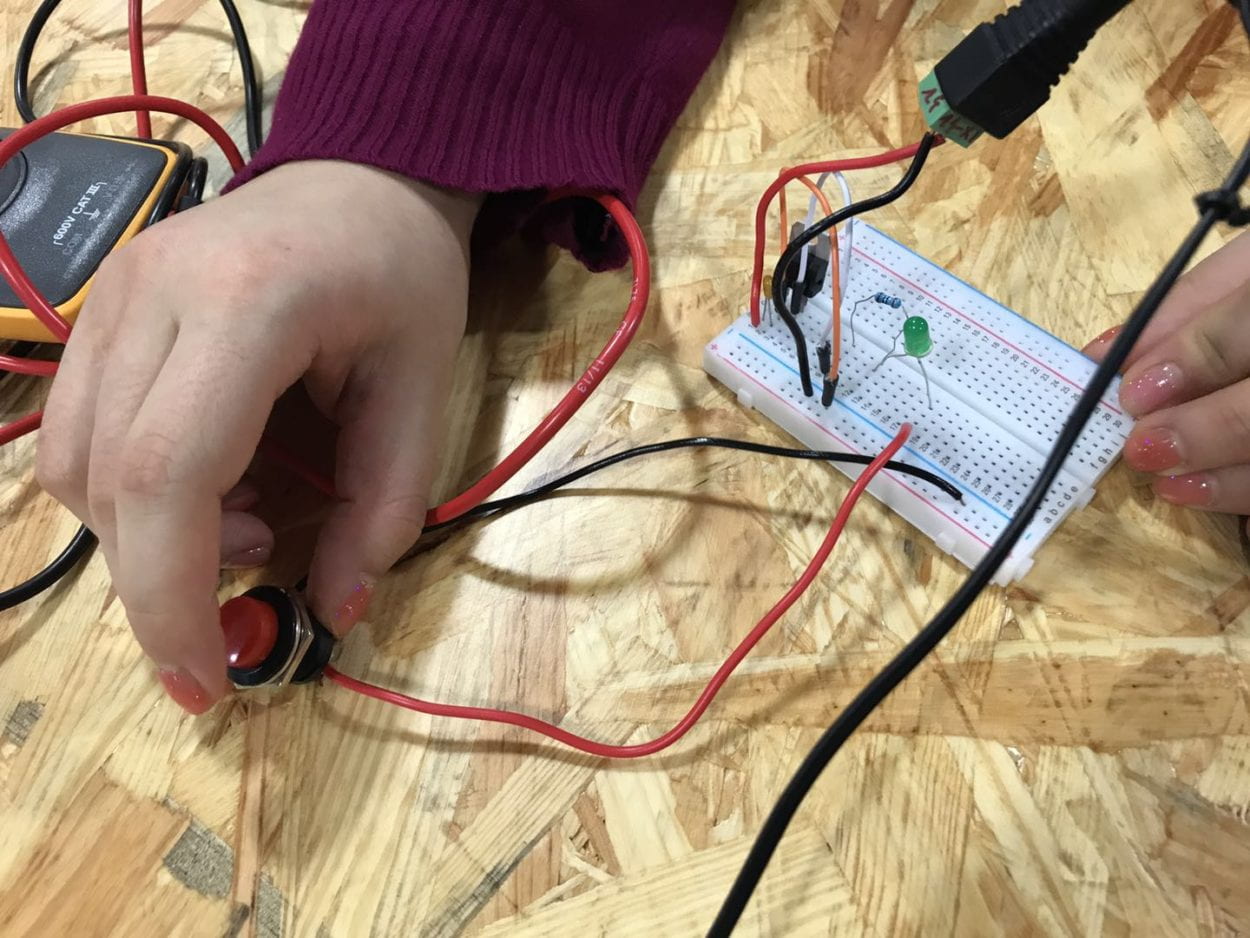
Circuit 1: Door Bell
Components:
- 1 * Breadboard–A pre-organized cable layout, easy to plug in jumper cables and other units’ legs. Good for organizing circuit.
- 1 * LM7805 Voltage Regulator–Turns 12V DC to 5V DC. This, with the power supply, gives our buzzer and LED a friendly 5V.
- 1 * Buzzer–Output. Add direct current and it plays a 2200 Hz pitch.
- 1 * Arcade Button–Input. Switch on and the current can pass
- 1 * 100 nF (0.1uF) Capacitor–Stores electricity while current is flowing into them, then releases the energy when the incoming current is removed. Capacitors can also be used to stabilize and smooth the flow of electricity.
- 1 * 12 volt power supply–Turns 220V AC to 12V DC.
- 1 * Barrel Jack–Convert the power in the cable into the form that the breadboard can process with
- Several Jumper Cables (Hook-up Wires)–Help with connecting the circuit
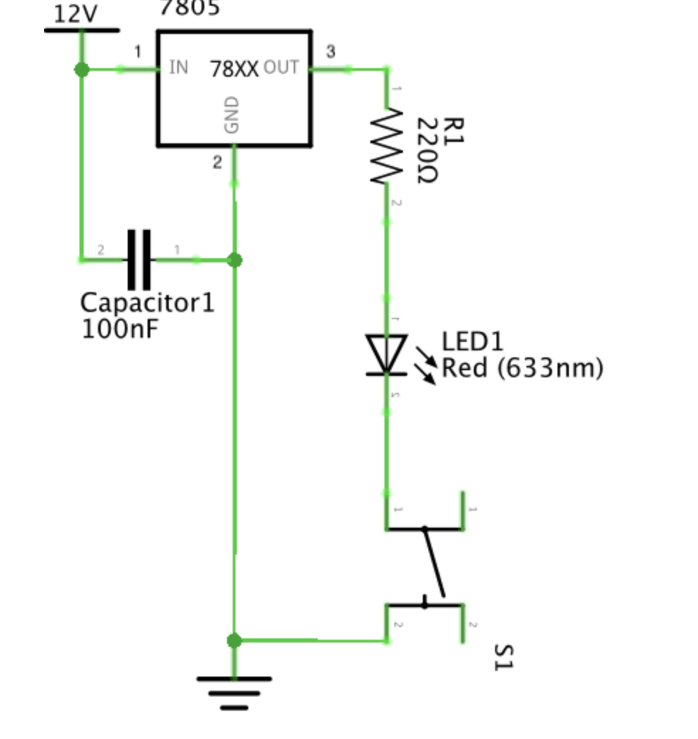
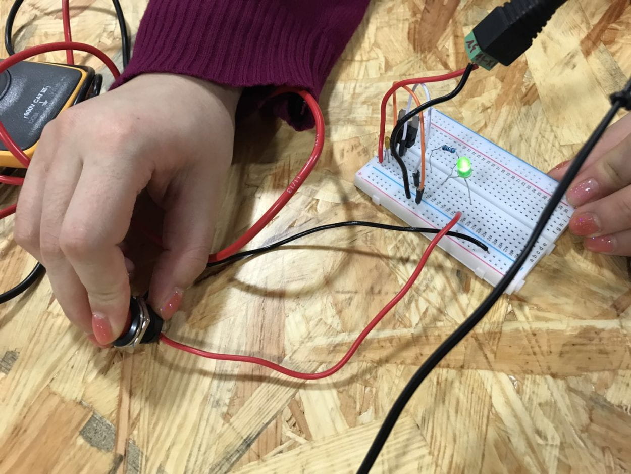
Circuit 2: Lamp
Components:
- 1 * Breadboard
- 1 * LM7805 Voltage Regulator
- 1 * Arcade Button
- 1 * 220 ohm Resistor–Help reduce the current and share the voltage so that the LED won’t pop.
- 1 * LED–Output. Polarized. Consume electricity and emits light.
- 1 * 100 nF (0.1uF) Capacitor
- 1 * 12 volt power supply
- 1 * Barrel Jack
- 1 * Multimeter–Test the resistance of the resistors.
- Several Jumper Cables (Hook-up Wires)
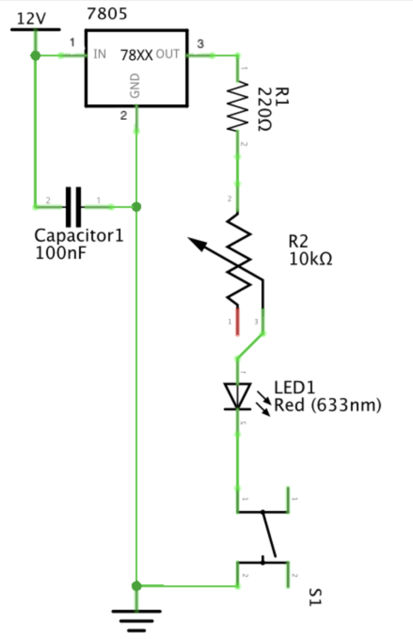
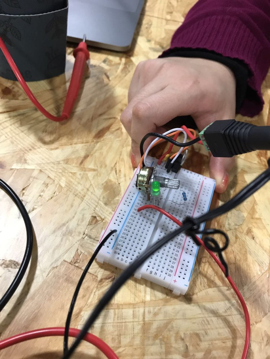
Circuit 3: Dimmable Lamp
Components:
- 1 * Breadboard
- 1 * LM7805 Voltage Regulator
- 1 * Arcade Button
- 1 * 220 ohm Resistor
- 1 * LED
- 1 * 100 nF (0.1uF) Capacitor
- 1 * 10K ohm Variable Resistor (Potentiometer)–Control the brightness of the LED using the change of the resistance.
- 1 * 12 volt power supply
- 1 * Barrel Jack
- Several Jumper Cables (Hook-up Wires)
Problems:
- Don’t know which is the front of the capacitor: the front is with the black box that sticks out.
- The negative is seen as the ground.
- The power should better be inserted into the very left/right column with specific signs of +/-
- Each row should be connected with cables.
- The very left/right column is not connected to the middle two columns.
- Always plug out the device when altering the circuit.
- The capacitor is both in parallel and series connection.
We’d also tested the push-button switch and found out that of the 4 legs of the switch, the diagonal 2 work to serve as a switch.
Soldering part
Tools:
Soldering iron: set to a specific degree
Soldering stand
Wire cutter and wire stripper
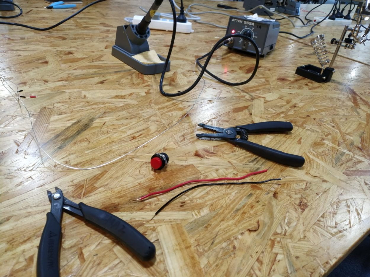
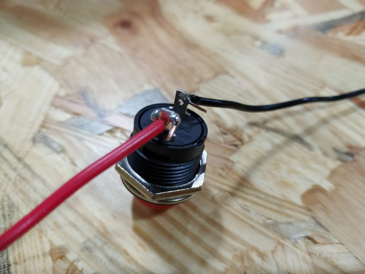
Problems:
- The tip of the soldering iron has some oxide coating and it increases the difficulty of melting the solder. To avoid failure, solder for a longer time/use steel wool to clean the oxide coating/don’t touch the oxidic parts of the iron
- I burned some of the outer of the wire. Correction: Be careful.
Answers to the questions
1. For the first two circuits, if you push the button (or switch), the circuit gives feedback: either buzzing or lighting up the LED. For the third one, if you turn the handle of the potentiometer while you push the button, you can control the brightness of the LED. The users can interact with the buzzer/LED with the help of the circuit.
2.
Yayoi Kusama
Infinity Mirrored Room -The Souls of Millions of Light Years Away, 2013