Recitation 1: Electronics & Soldering
Instructor: Marcela
Partner: Ally
Materials)
- Breadboard – a device for temporary prototyping electronics as the layout allows easy access for making connections and experimentation in the production stages.
- LM7805 Voltage Regulator – to maintain voltage output – a regulator is incorporated for sustainability of the Volt current. In this case, it allowed the 12V DC to be at 5V DC which would not blow the LED.
- Buzzer – the output signal once pressed (input). For our circuit prototyping, it allowed us to confirm that the circuit was functioning.
- Push-Button Switch – (can be input or output) let the electricity flow through the circuit.
- Arcade Button – an alternative input element to the push-button switch. Serves the same purpose, with a different design.
- 220 ohm Resistor – The resistance that maintained our LED intact. An additional obstacle for the voltage to pass.
- LED – light-emitting diode, served as output when circuit was functioning.
- 100 nF (0.1uF) Capacitor – for the LM7805 Voltage Regulator to be functional.
- 10K ohm Variable Resistor (Potentiometer) – With this resistor we were able to control the current going to the LED, thus being able to dim it and brighten it.
- 12 volt power supply – The 220V AC was translated to 12V DC which was a safe Voltage for us to prototype and experiment on.
- Barrel Jack – were able to connect the power supply to the Breadboard with the Barrel Jack, (much like a plug power converter).
- Multimeter – although contains many more options, we used the Multimeter to detect the appropriate resistor (of 220 ohm).
- Several Jumper Cables (Hook-up Wires) – flexible, easy to plug in wires that worked very well in Breadboard connections for our circuits.
CIRCUTS
- Buzzer
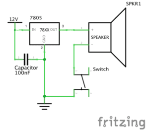
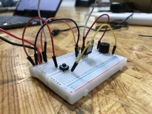
Although fairly simple, this circuit was crucial in my foundational understanding of Energy and Ground. We specifically made sure to use the red jumper cable to connect the electricity flow to the buzzer component – to visually emphasise the concept of ‘power’. In addition, the black jumper cables were emphasising the connection to the Ground.
2. LED
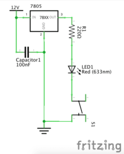
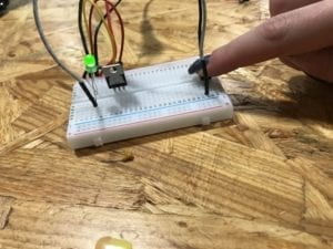
Although we were pretty lucky in managing to find the correct corresponding holes on the Breadboard in the first circuit, the second one rose some challenges. In this phase, it was reiterated that the ‘legs’ of the LED are very specifically classified – the longer wire corresponds to positive/power, and the shorted leg corresponds to negative/ground. After we figured this out, we were able to switch around the LED and get the electricity running though the circus, thus allowing the LED to light up.
3. Dimmable Light
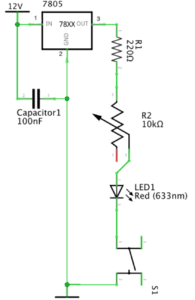
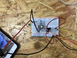
In this phase, we added a Potentiometer to customise the brightness of the LED. Although I cannot speak about the first attempt (as it was not successful), we decided to build it from scratch again. I think this was an important aspect, because once we realised we cannot track the bug/error, we chose to not waste time in rebuilding each part of the circuit separately. I now reflect that we were able to do this as it is a still fairly simple design, which got me wondering how I would tackle such an issue on a larger prototype. How the two attempt might have been different? In this stage, I realised it was crucial to understand the logistics behind all of the components, because as we gained a greater understanding of the hardware we were working with (by the help of the fellows), the logical layout of the design made sense (in my head) thus it was more manageable to replicate it physically.
QUESTIONS
1. While reading “The Art of Interactive Design” I was able to differentiate between the concept of “interaction” and “reaction” (“It takes two people to have a conversation, and it takes two actors to have an interaction”). When thinking about the circuits we constructed, I applied the concept of the Degrees of Interactivity to better comprehend what our end-goal was. For example, when thinking about the buzzer – a button is pressed, therefore a sound is outputted – which I would consider a low degree of interactivity. The user does not have a choice of input, and there is only one possible output. In comparison, the addition of the Potentiometer allowed the degree of interactivity to rise – the user now has a choice of where to turn the ‘pointer’, and thus the output varies also. I also began to think how else this degree might increase in my future creations – the instructions – THE CODE. By customising the settings (both possible input and output) the degree of interactivity rises. This really sparked my curiosity of “what else I can make happen”, especially in relation to Art and Design!
2. I currently began exploring how Artificial Intelligence is used for style transferring when creating Art [current favourite digital artist Gene Kogan]. I have never associated art with computers before University, so to start realising how well they interlink when creating is very motivating for an aspiring artist in the Digital Age. This emerging technological era just shows how tools like Interaction Design or Physical Computing can be customised to flourish creativity. I realise the power you gain once you learn the native language, in this case ( the instructions through ) CODE in relation to the hardware. All of these tools aid us, but cannot do for us, therefore learning to follow an idea from initial stages of development to an end-product requires, not only diligence, but fundamental understanding of the “so-called place” you are creating in or with (online / Breadboard / robotics / etc). For Art to be Interactive, the artist has to know their direction they want to take with their audience and the Digital Age tools serve as an accessible source for exploration of own ideas.