CONTEXT AND SIGNIFICANCE
My definition to interaction:
Interaction is a way in which a connection can be undertaken between a user and the product he or she is using. It is the process of receiving information from the user, processing and transforming it, and finally turning it into an output for the user.
My previous group project involved creating a self-arming protective suit that, like Iron Man’s MARK 42 (Prodigal Son), assembles itself with a single user action. Our product responds when the user enters a certain amount of information, according to my definition of interaction. For this midterm project, I collaborated with my teammates to design a Transformer – Stepper Destroyer that is equipped with numerous sensors, which are devices that can interact with the user. For example, there may be some irregularities in a specific part of the vehicle that the user must discover and correct in order to gradually unlock the Transformer’s transforming function. Rather than a traditional Transformer toy that can only be manually transformed between car and human form, our project is more akin to an enlarged version of a toy Transformer, only with more interactive elements. It’s far more engaging and entertaining than the standard product. Our target audience continues to be traditional toy users, and it can bring them more joy. However, by upgrading our product again, we may be able to achieve a higher level of mechanics and interactive skills similar to Boston Dynamics’ robots.Of course, when it reaches that height, it’s not simply just a toy.
CONCEPTION AND DESIGN
The following interactive elements are included in our program:
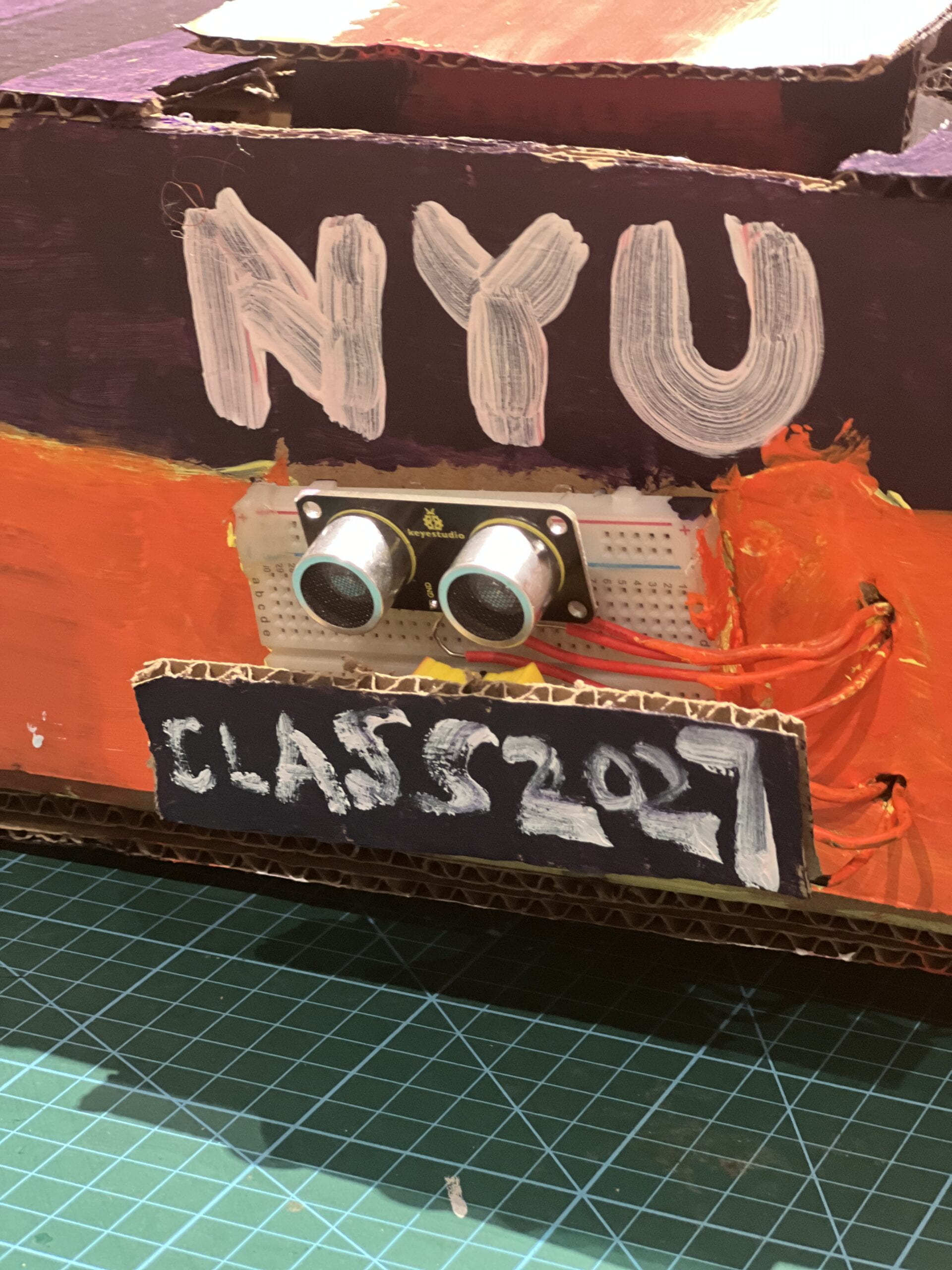
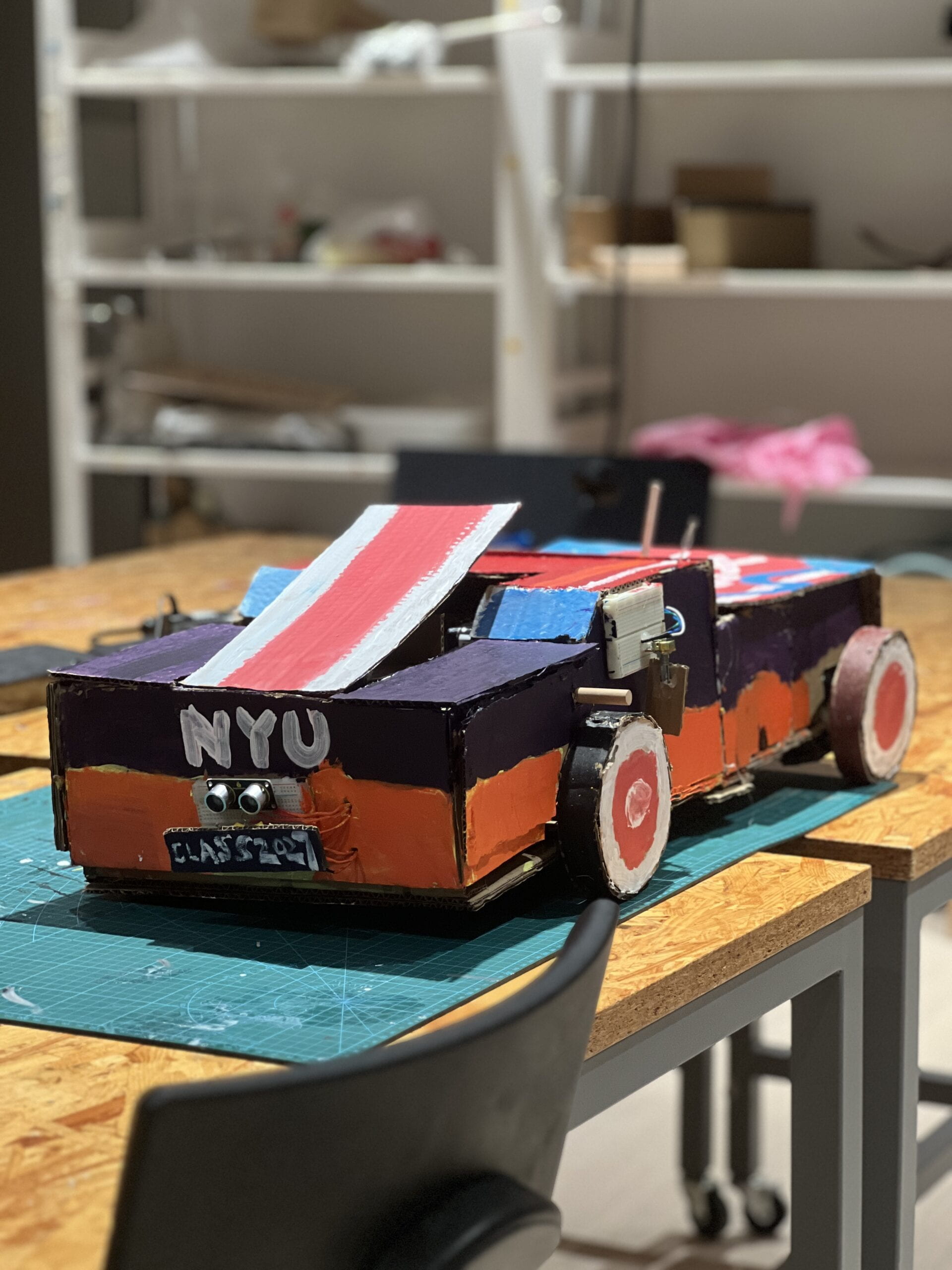
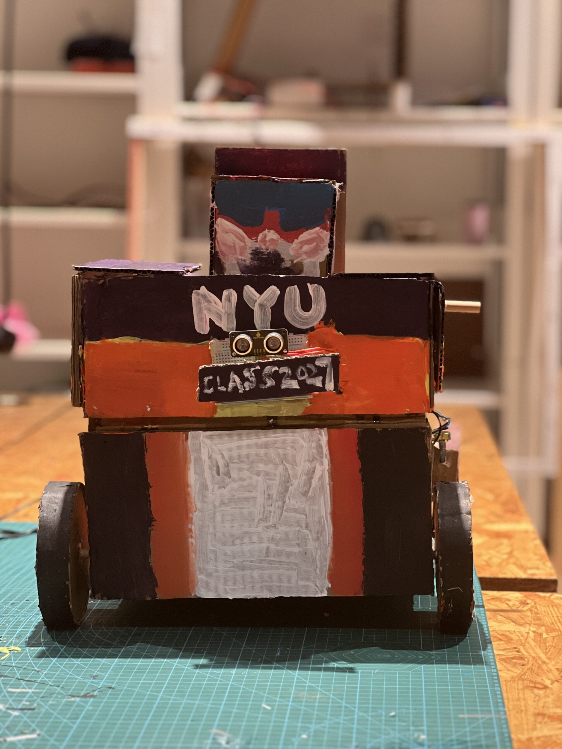
- Ultrasonic Distance Sensor (headlights): We included a sensor in the center of the front of the car, which was plugged into the breadboard of the front of the car and connected to an ArduinoUno. When it detects that someone is in front of the car or that someone’s hand is waving in front of the car, it emits a voice: “Hi, I am Stepper destroyer created by Eric and Evan. I am Stepper destroyer created by Eric and Evan. If you see any stepper motor in front of me, you can press the button on my container and help me chase it. Anyway, nice to see you.Could you do me a favor? I don’t feel well today. Parts of my body maybe needs to be fixed.”
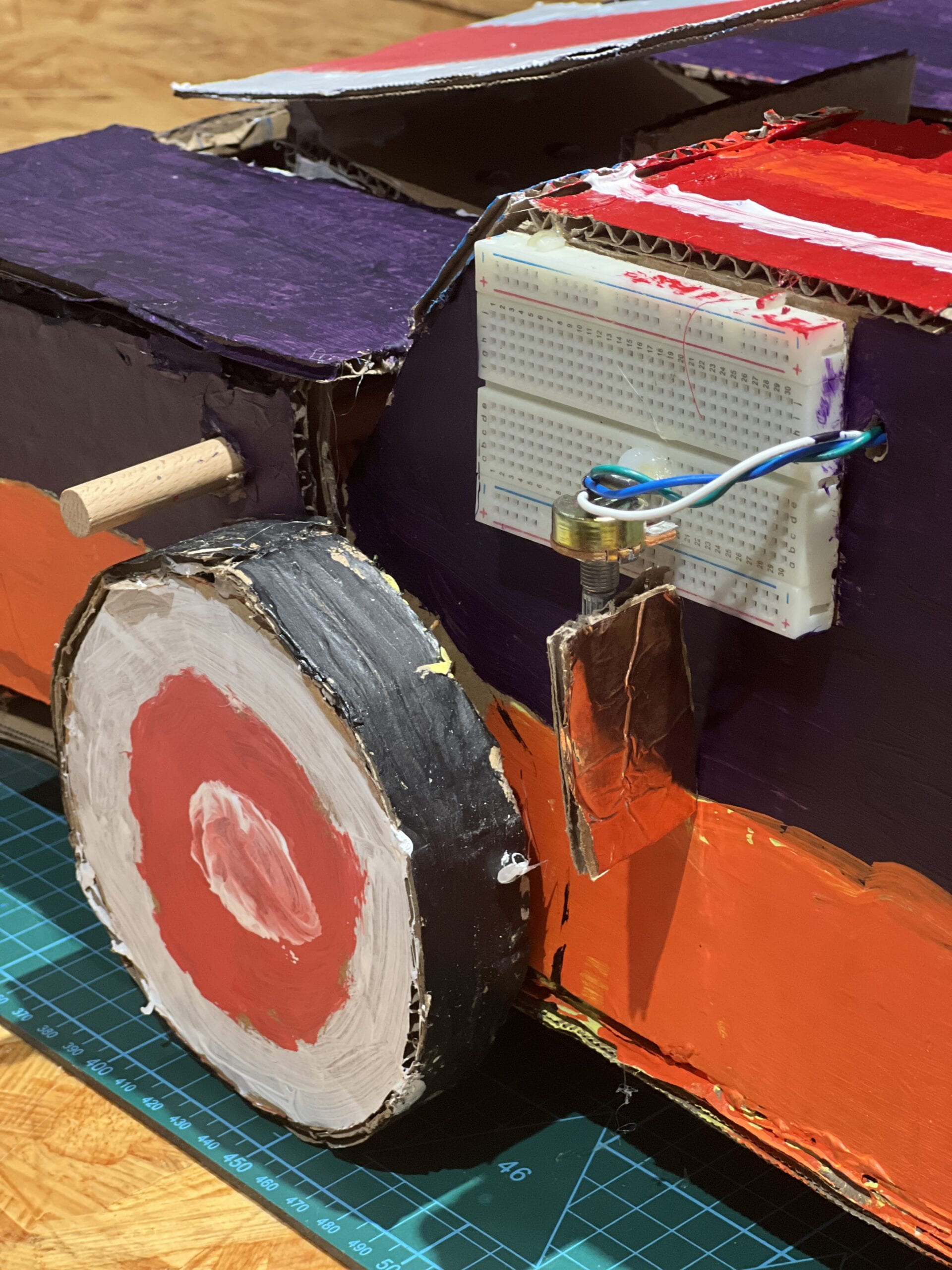
- Variable Resistors (Reversing Mirror): we used a potentiometer and put a layer of copper tape on the knob, which was designed as a reversing mirror because of its reflective effect, and inserted it on a breadboard. It was connected to an ArduinoUno, and when it was rotated, a voice was emitted: “Thank you, there was dirt on my antenna, now I can recieve the signals.”
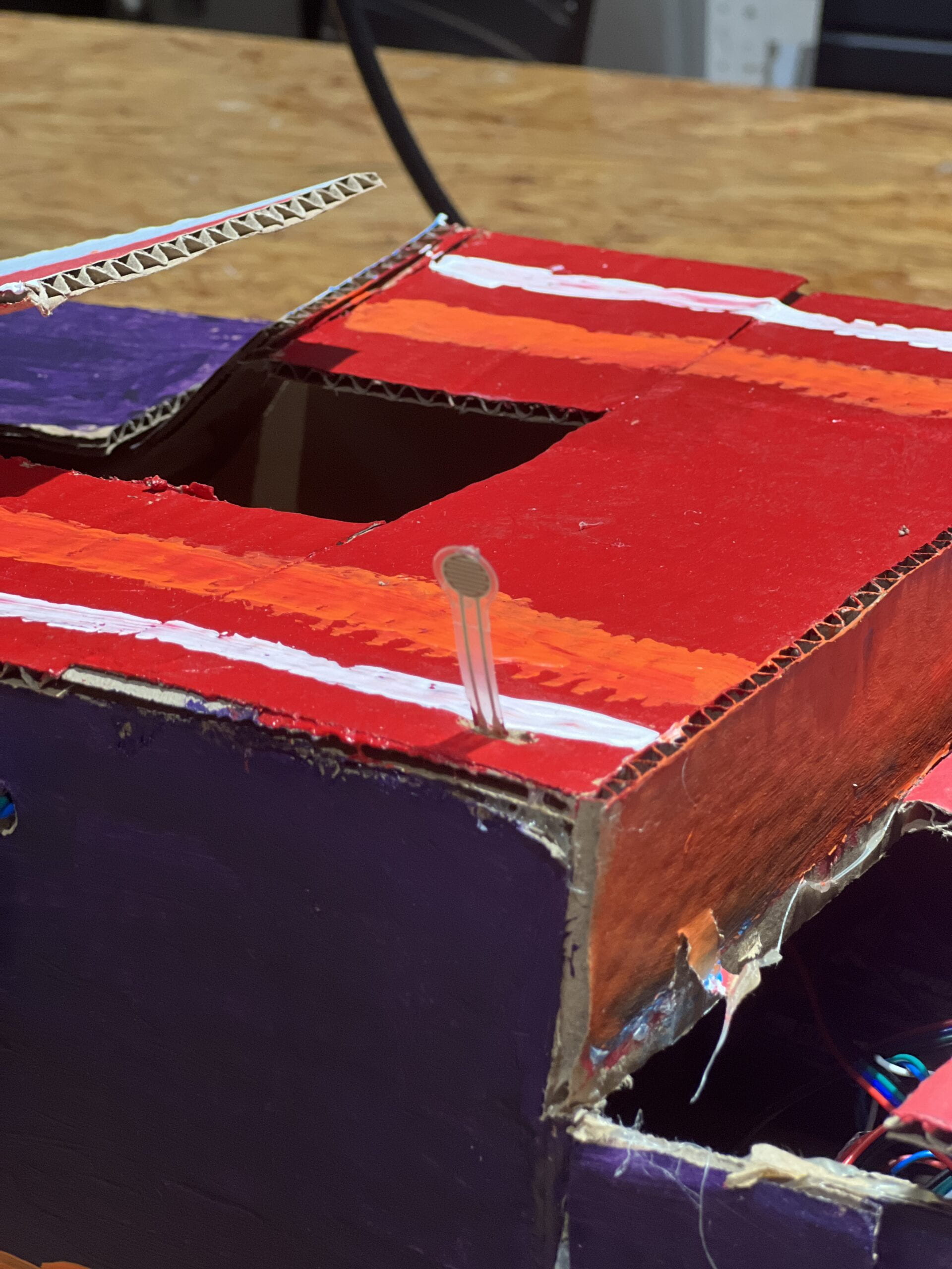
- Force Pressure Sensor (antenna): We installed a sensor on the roof of the car, which is connected to the Arduino Uno by an extended wire, and when someone pinches its antenna, it will emit a voice: “Thank you, there was dirt on my antenna, now I can recieve the signals.”
- Slide Sensor(logo): Right underneath the Ultrasonic Distance Sensor, we added a Slide Sensor and pasted “Class 2027” on top of the slide as its logo, when it is moved to the right position, it will emit a voice: “Thank you, there was dirt on my antenna, now I can receive the signals. When it is moved to the right position, it will emit a voice: “Thank you, now my logo is straight and I feel better. Finally, when all the sensors are triggered, it will emit another voice: “Thank you so much, now I can show you my secret. Autobots roll out.” Thus, we have unlocked its morphing function.
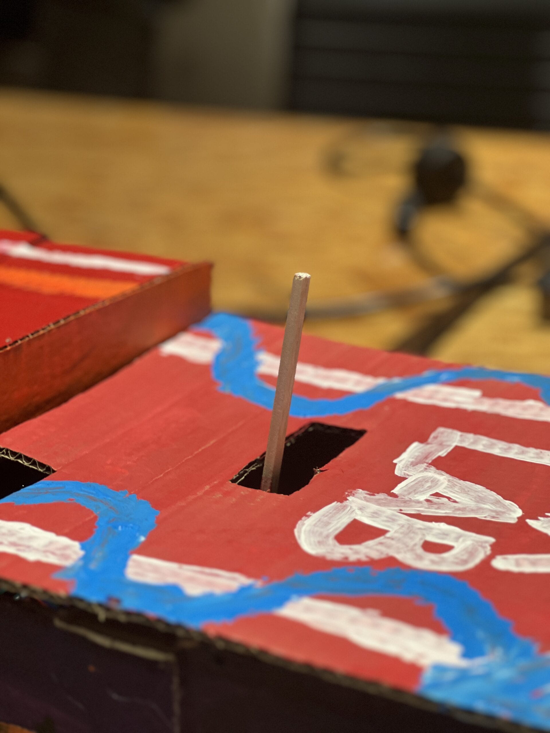
- Push Buttun: We installed a button on the rear of the car and glued a long wooden stick on top of the button so that it could stick out of the car. When the user pushes the stick and presses it for a longer period of time, the Transformer can run farther.
- IR Remote: We added the only device that can be remotely controlled in the project, which is its morphing function. When the user presses the button on the remote control, the Transformer will transform from human form to vehicle form.
This part was inspired by the opening credits of Transformers: Age of Extinction, where Optimus Prime is severely injured and is able to move around after Cade Yeager repairs every part of Optimus Prime.
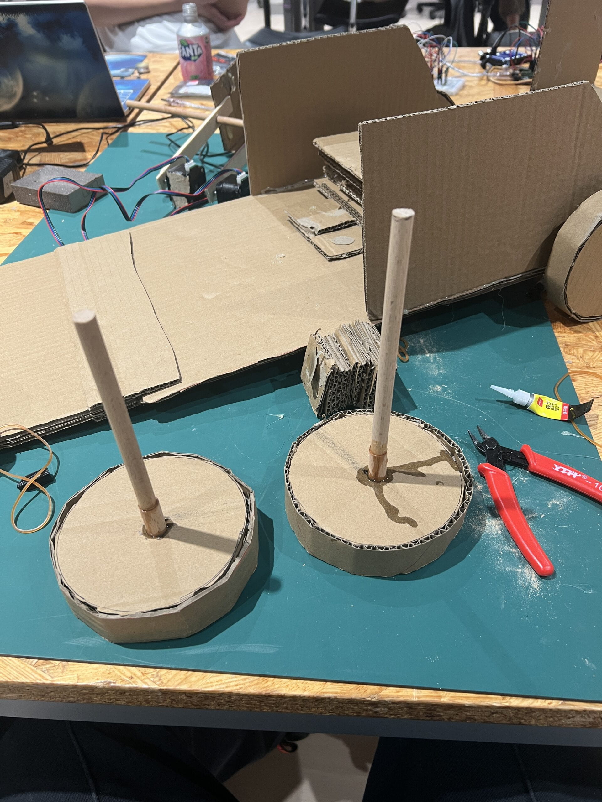
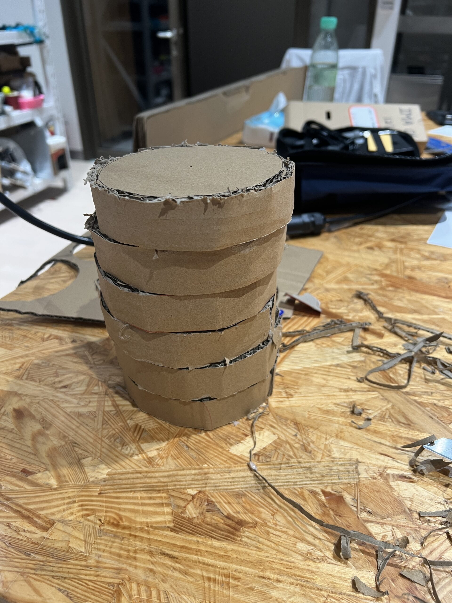
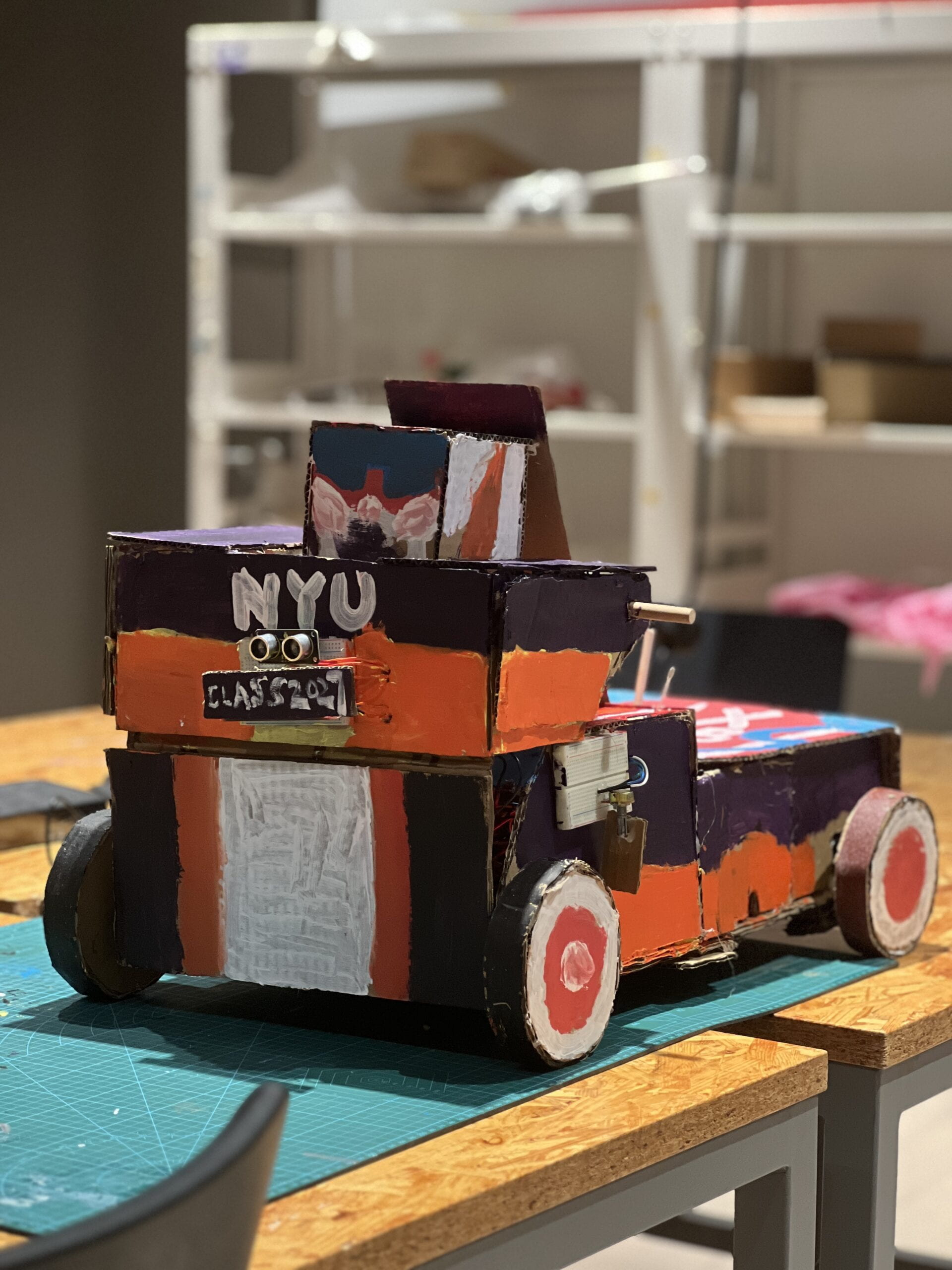
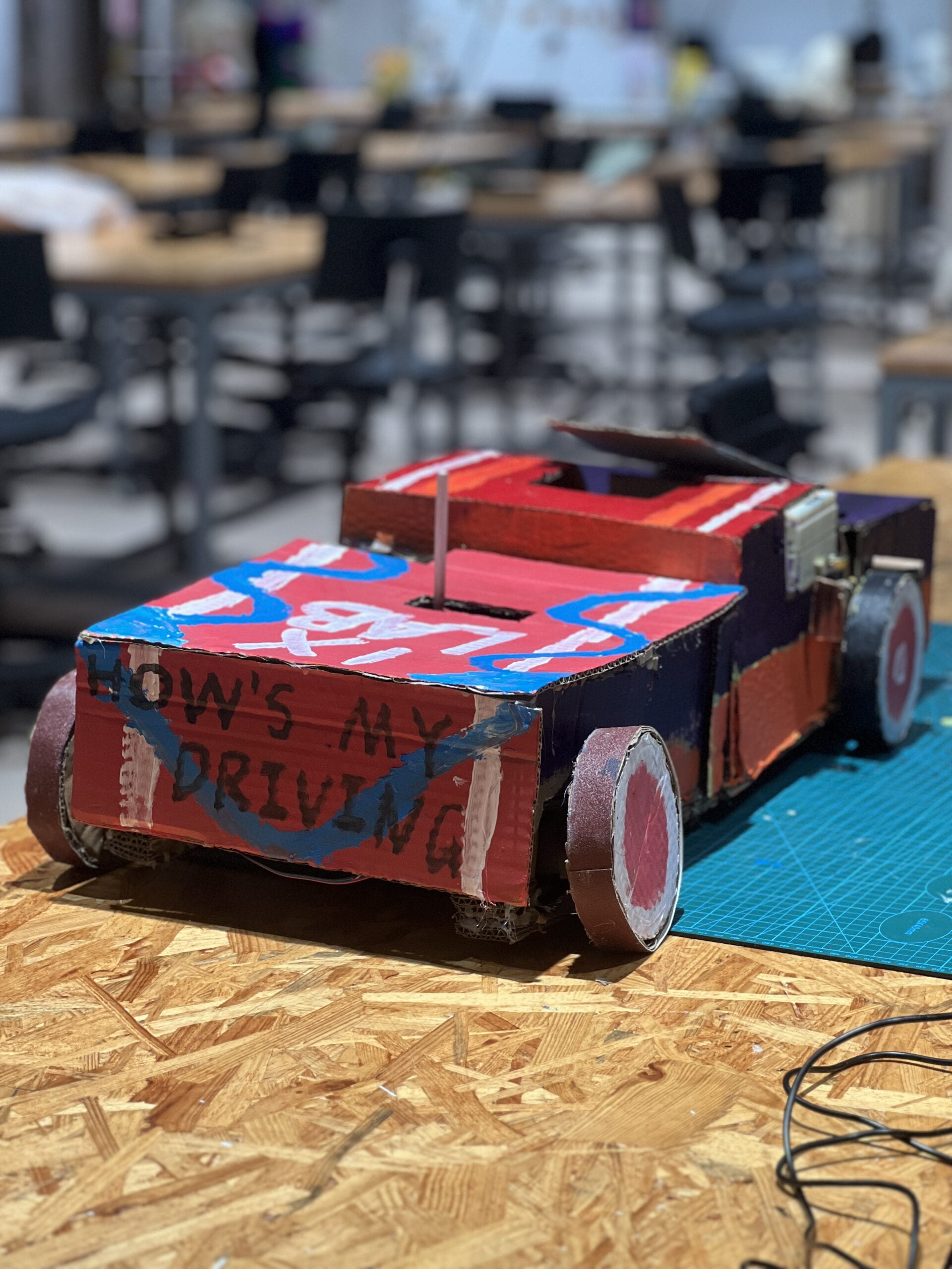
For the main body of the vehicle, we built it out of cardboard, which is lightweight and inexpensive.

(image credit:http://xhslink.com/ciCkPv)
After we settled on building a Transformer, we started designing its mechanics. We designed it as an 80cm long, truck with a width of 30cm. For the deformation part, we used a simple mechanical structure. As shown in the picture below.
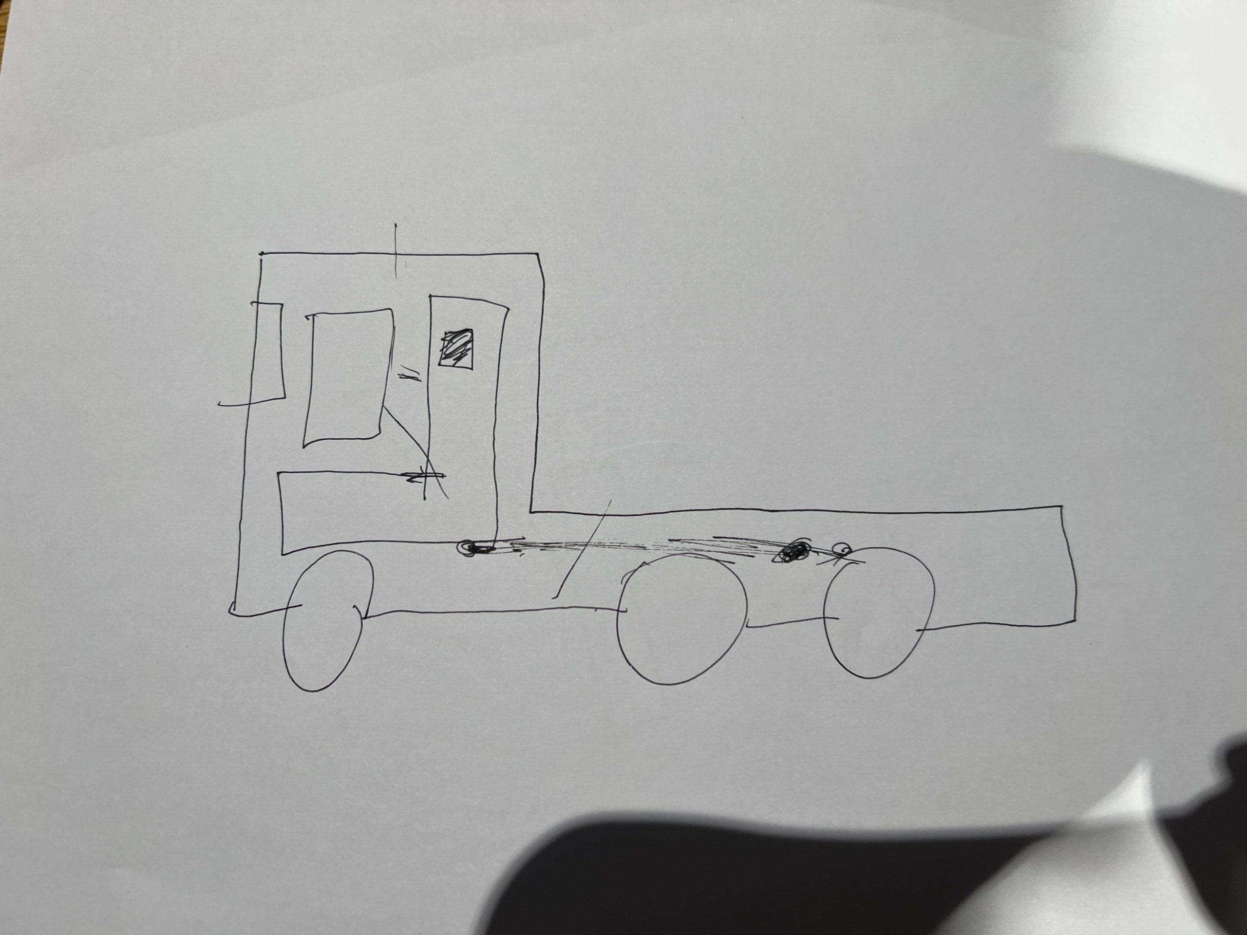
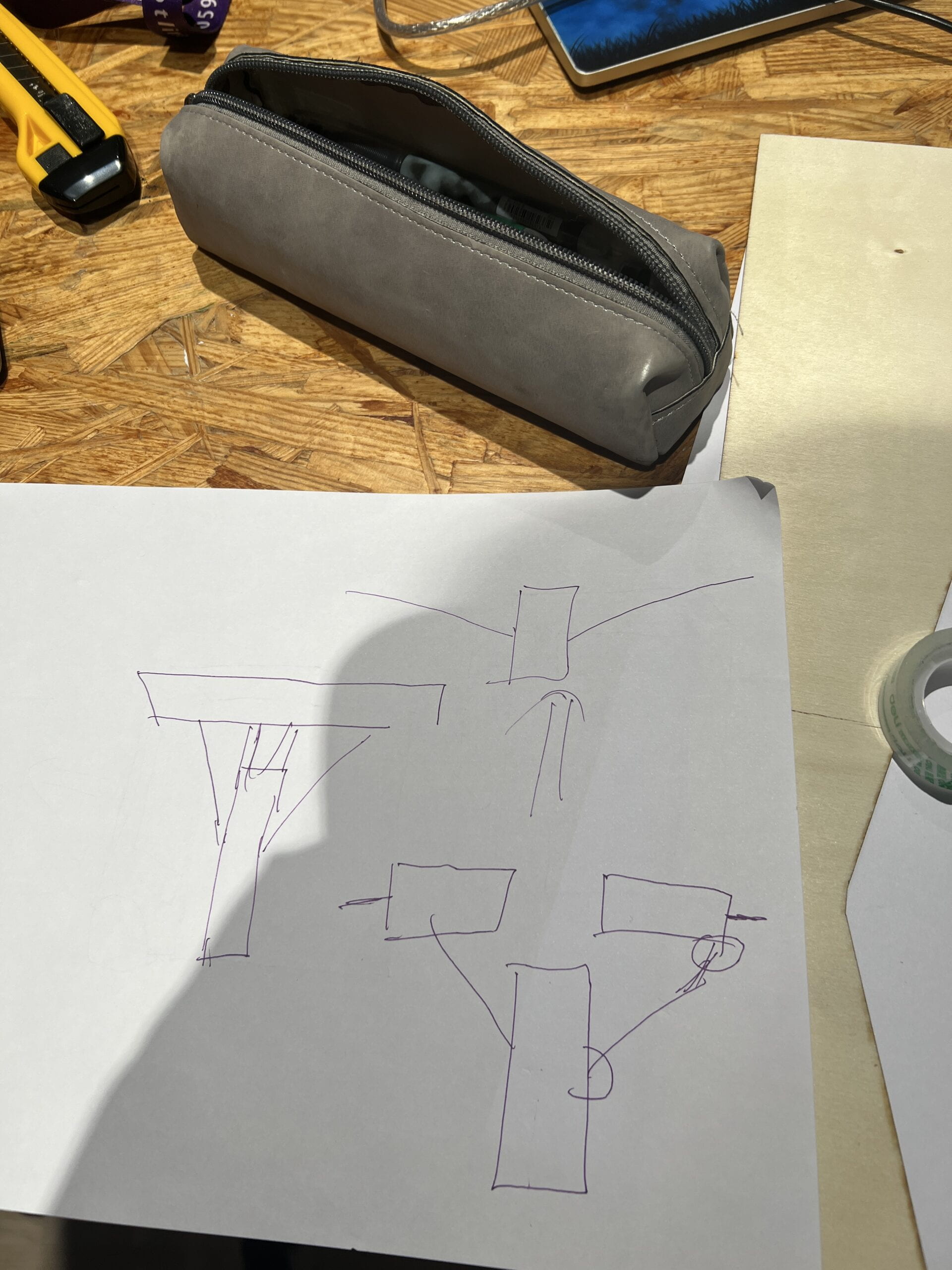
(We are inspired by:https://www.youtube.com/watch?v=vOTkxDtlzN0)
They will be driven by stepper motor.
At the same time, our truck is rear-wheel drive, hich means that its power source is only the two motors at the rear of the truck.
Originally, we planned to mount each stepper motor directly to the vehicle with hot glue, but during our testing, we discovered that the stepper motor had very little time to overheat, and the high temperature melted the hot melt glue. We were fortunate to receive assistance from Prof. Andy Garcia, who converted their connection structure into a 3D printed bracket, allowing the stepper motor to dissipate heat more effectively and mechanically stable.
Previous: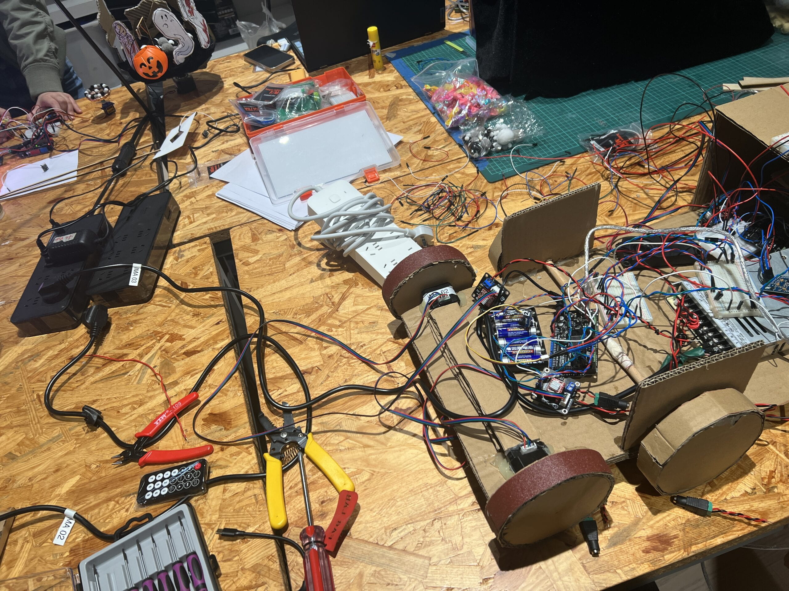
After: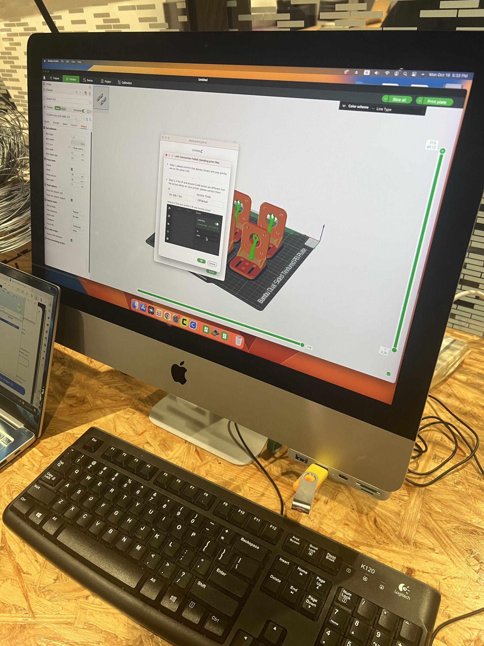
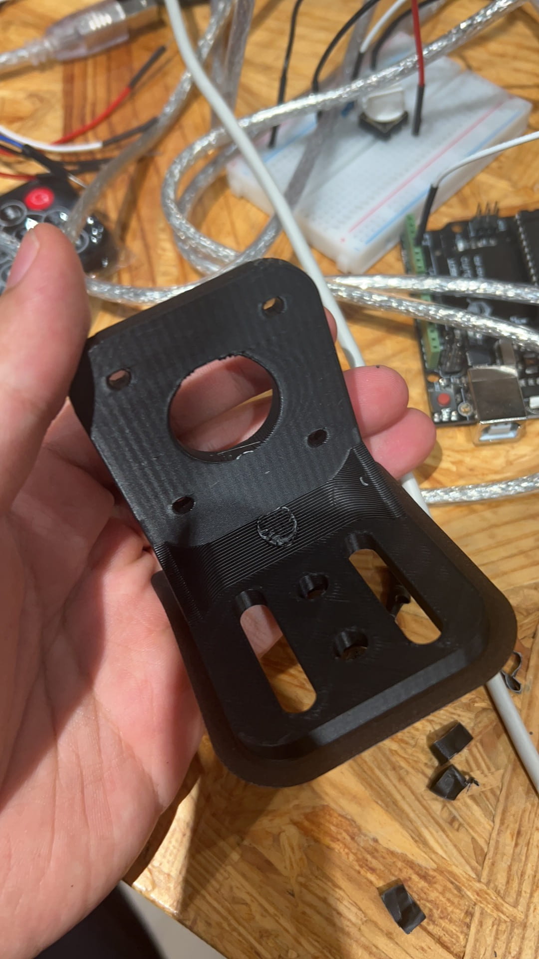
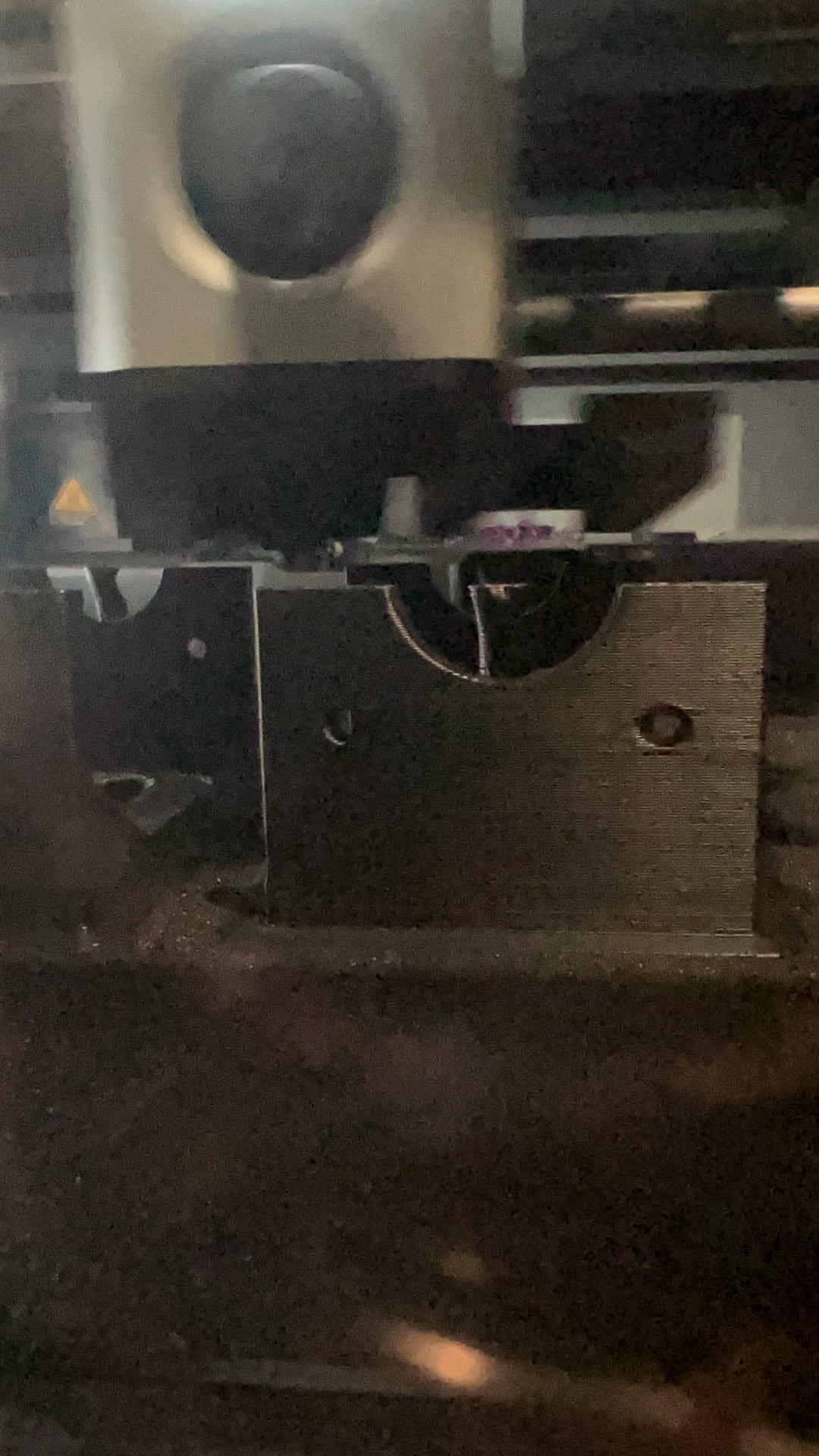
(The mount of Nema17 is from:https://www.thingiverse.com/thing:1901467)
We also used laser cut to create the force arm for the deformation part.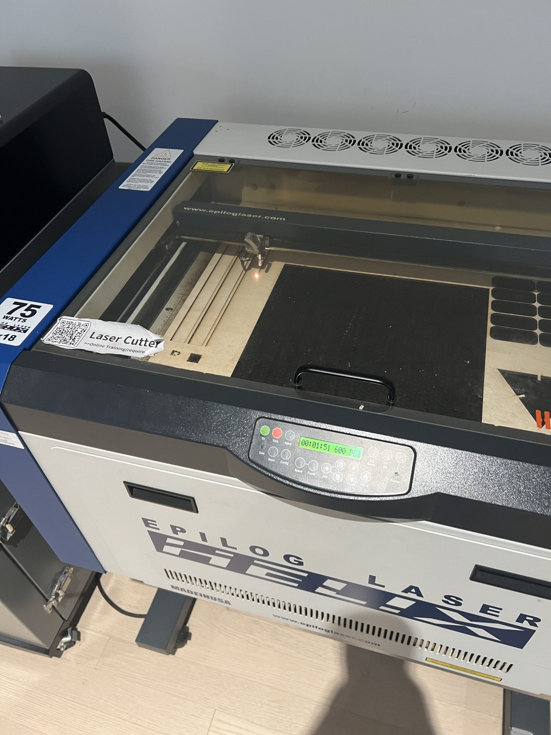
FABRICATION AND PRODUCTION
The most difficult part of our fabrication and production steps is the mechanical structure and code. In this project, I was primarily responsible for the Transformer’s mechanical structure and appearance. The first issue we encountered in our tests was that one stepper motor could not lift the front part of the Transformer, i.e. it could not carry the weight required to transform it. We wondered if two stepper motors could work together as a result of this. The millis code was then tried, but it did not work. We encountered so many difficulties on the first night we began working on the project that we had to prioritize other aspects of the construction.We only solved the puzzle after Prof. Andy Garcia showed us how to make the two stepper motors work together.
During the user testing, Kevin also made several other suggestions, such as adding springs or shortening the length of the robotic arm’s force arm. We tried some of these ideas, such as shortening the force arm. However, accidents occurred during testing, such as when the motor worked for a while and then was unable to lift the front part of the car again. We changed the part of the motor that raised the front end to become a person to lowering it to become a truck to eliminate the possibility of this failure.
But after we finished the main body of the car, we discovered something we hadn’t expected: the torque of the stepper motor wasn’t enough to propel an entire car. Even though I glued more friction material on the wheels, it still didn’t work smoothly.Fortunately, we were advised to shorten the car’s length. Then we repeated the process, removing the six’s two middle wheels because they provided too much resistance. We eventually succeeded.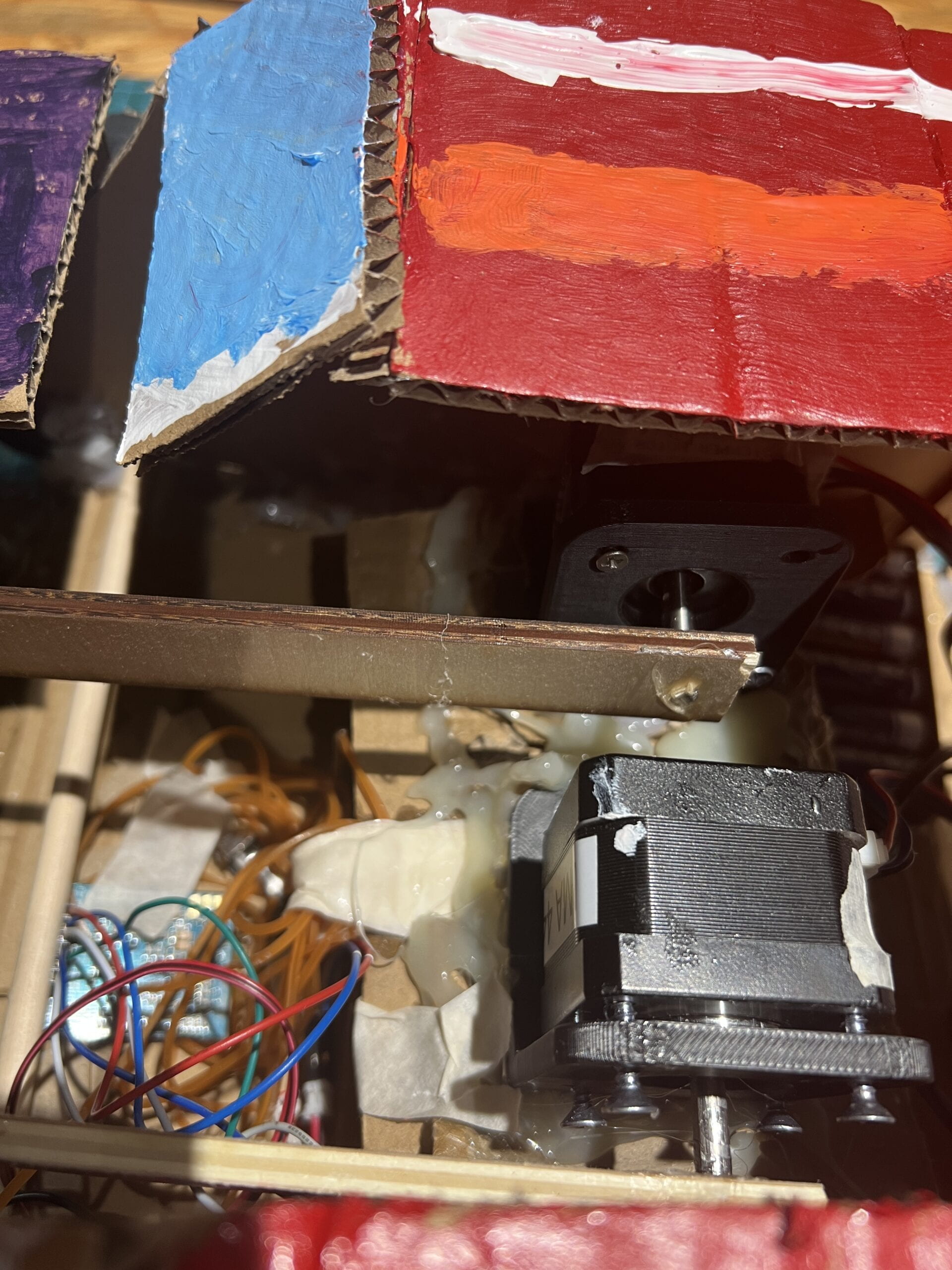
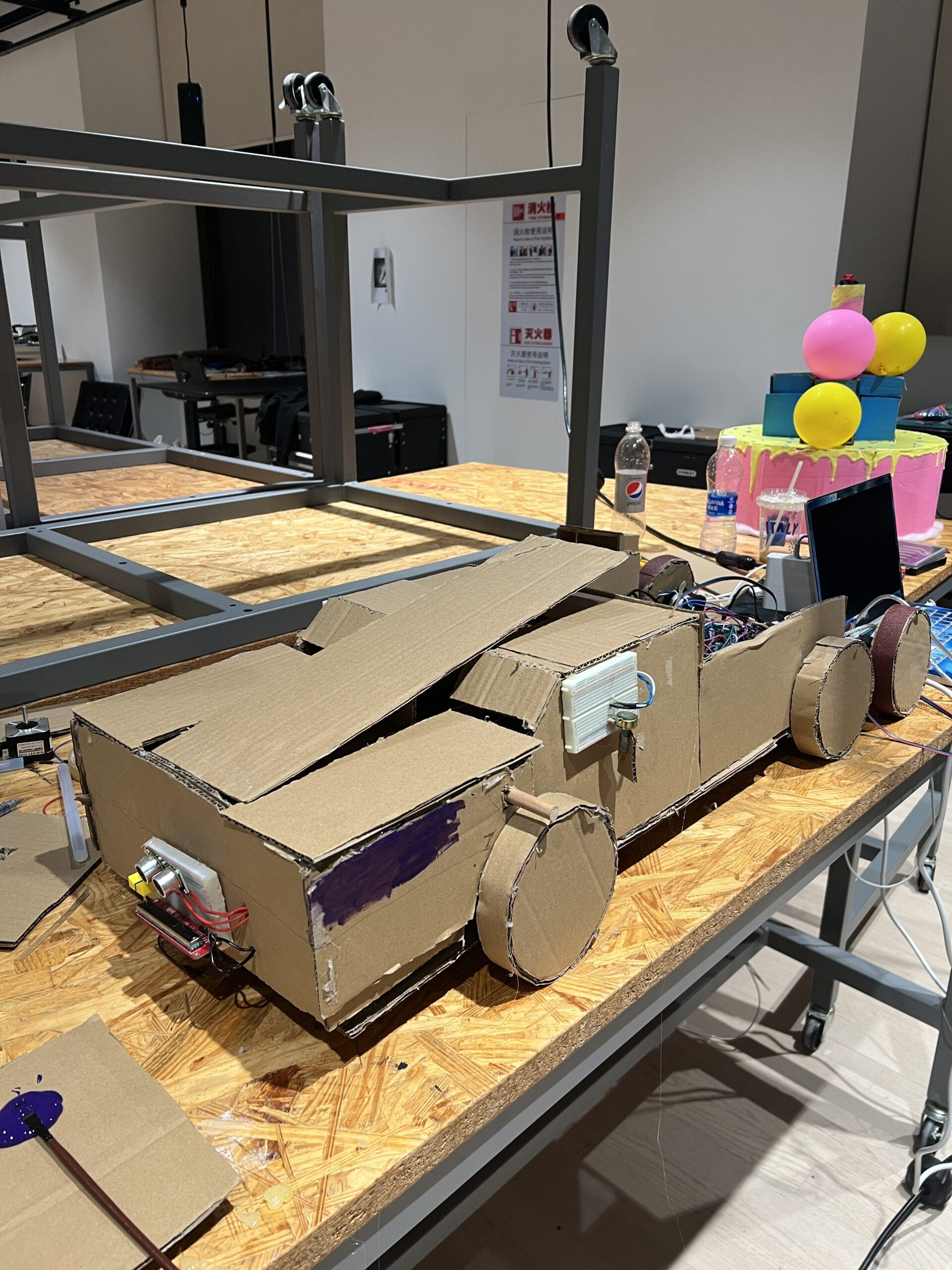
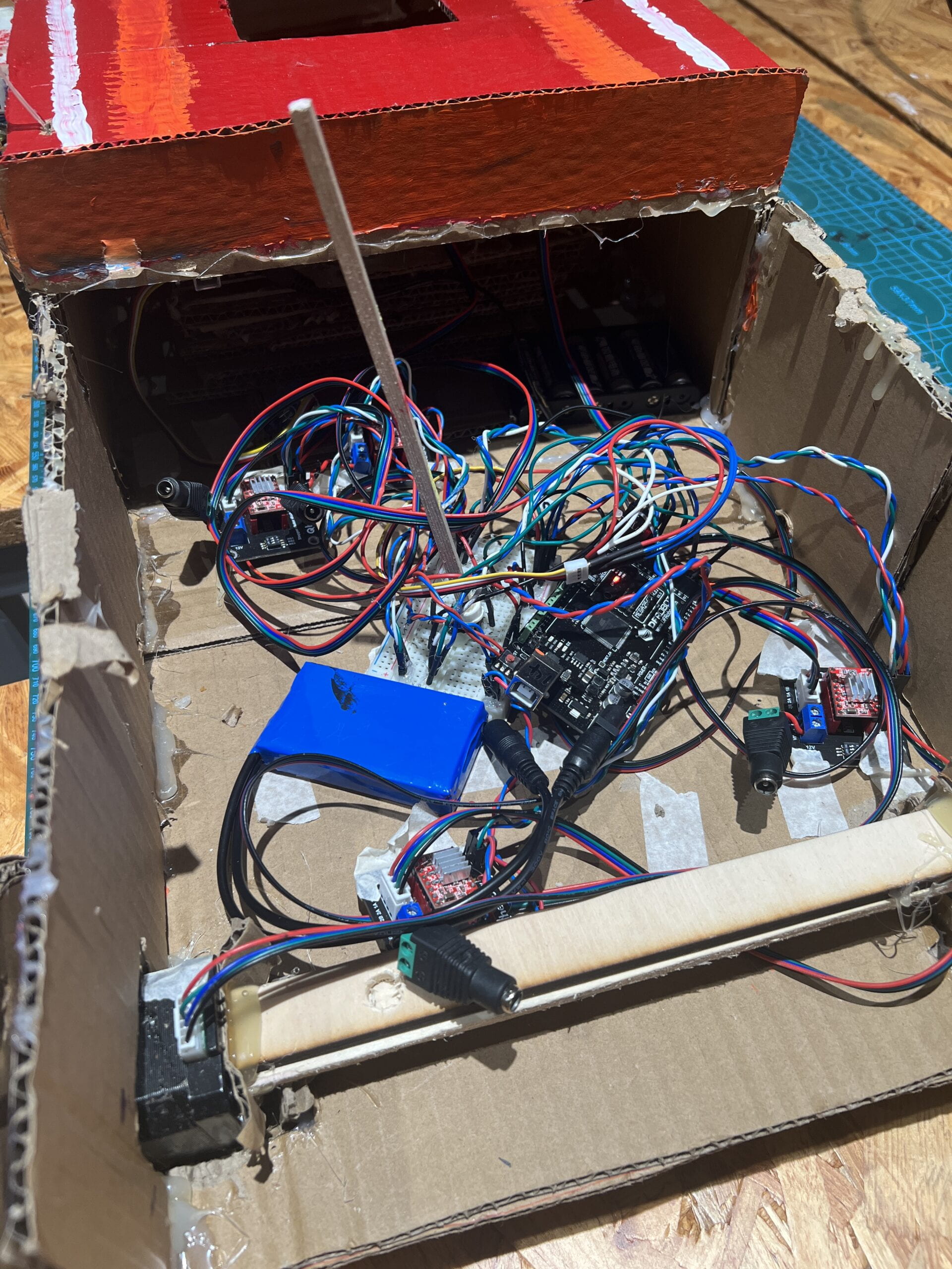
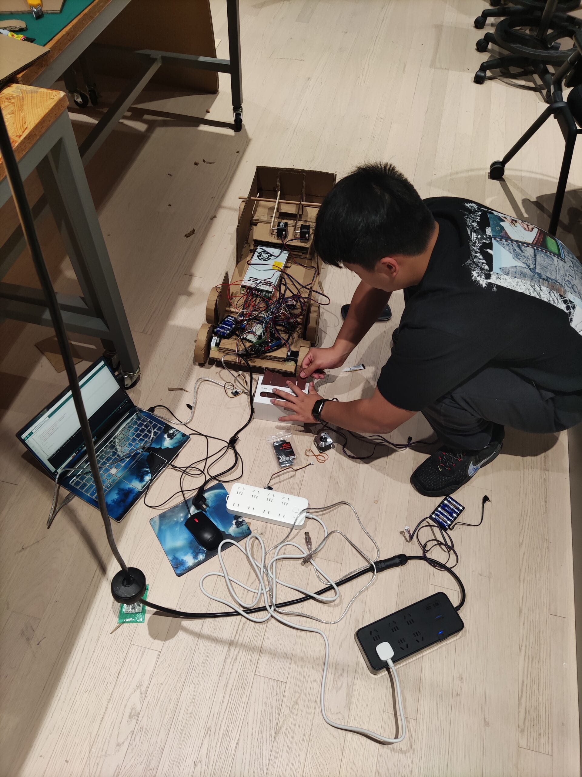
We intend to expand the Step Destroyer’s capabilities. However, we discovered that the Arduino is too small to hold so much code, so we had to use multiple Arduinos. But we didn’t know how to connect multiple Arduinos without IR receivers and emitters, and we assumed that using multiple IR’s would be too complicated and difficult for physical wiring. (As shown in the previous image, even though we had organized the wiring, it was still very messy.) As a result, we abandoned the idea of adding more.
And there are numerous issues that arise as we connect them or put them into service. For example, we tried to use a 350w 12v power supply, but we don’t understand why one of the wires always shorts out when connected to four wires. So we chose lithium batteries for power supply, but unfortunately, the lithium batteries were depleted very quickly during the last demonstration, so we had to demonstrate other Transformer functions.
In addition, the ArduinoMega we borrowed from ER had several unresponsive ports. We checked all parts of the device at the time, including the connection, whether the motor was available, whether the power was sufficient, and so on. Knowing that a few hours later, when we replaced its pin, we discovered that the problem was with the Mega’s ports.
Of course, the stepper motor took up far too much of our time in this project; it was inconvenient and did not provide me with enough functionality. We abandoned the idea of adding an arm to the project because it was too cumbersome and didn’t give me enough power, making it a unique “centaur” form of a Transformer from a planet other than Cybertron. Our theory is that he was a valiant warrior who lost his arms while defending
Arduino Uno (or see the codes here)
#include SoftwareSerial.h;
#include SD.h ;
#include EMIC2.h;
#include IRremote.h;
//I don’t know why the blog eats my library every time so I //can’t use the punctuation for the library.
IRsend irsend(3);
#define RX_PIN 5
#define TX_PIN 6
int first = 0;
int count1 = 0;
int count2 = 0;
int count3 = 0;
const int trigPin = 9;
const int echoPin = 10;
long duration;
int distance;
int melody[] = {
139, 165, 175, 196, 208, 233, 247
};
float noteDurations[] = {
4, 4, 4, 16, 8, 8, 16
};
void setup() {
pinMode(trigPin, OUTPUT);
pinMode(echoPin, INPUT);
Serial.begin(9600);
emic.begin(RX_PIN, TX_PIN);
delay(1000);
emic.setVoice(1);
emic.setRate(150);
emic.setVolume(18);
}
void loop() {
digitalWrite(trigPin, LOW);
delayMicroseconds(2);
digitalWrite(trigPin, HIGH);
delayMicroseconds(10);
digitalWrite(trigPin, LOW);
duration = pulseIn(echoPin, HIGH);
distance = duration * 0.034 / 2;
Serial.print(“Distance: “);
Serial.println(distance);
delay(10);
if (distance < 20 && first < 1) {
for (int thisNote = 0; thisNote < 8; thisNote++) {
float noteDuration = 60000 / 183 * 4 / noteDurations[thisNote];
tone(8, melody[thisNote], noteDuration);
int pauseBetweenNotes = noteDuration * 1.05;
delay(pauseBetweenNotes);
noTone(8);
}
emic.speak(“Hi, I am Stepper destroyer created by Eric and Evan. If you see any stepper motor in front of me, you can press the button on my container and help me chase it. Anyway, nice to see you.”);
emic.speak(“Could you do me a favor? I don’t feel well today. Parts of my body maybe needs to be fixed.”);
first = first + 1;
}
if (first == 1) {
int sensorValue1 = analogRead(A0);
Serial.println(sensorValue1);
int sensorValue2 = analogRead(A1);
Serial.println(sensorValue2);
int sensorValue3 = analogRead(A2);
Serial.println(sensorValue3);
if (sensorValue1 < 300 && count1 == 0) {
emic.speak(“Thank you, my rearview mirror was opposite, that is why I can’t see the back.”);
count1 = 1;
delay(1000);
}
if (sensorValue1 400 && count2 == 0) {
emic.speak(“Thank you, there was dirt on my antenna, now I can recieve the signals.”);
count2 = 1;
delay(1000);
}
if (sensorValue3 > 300 && sensorValue3 < 700 && count3 == 0) {
emic.speak(“Thank you, now my logo is straight and I feel better.”);
count3 = 1;
delay(1000);
}
if (count1 == 1 && count2 == 1 && count3 == 1) {
for (int i = 0; i < 3; i++) {
irsend.sendNEC(0xF7C03F, 32);
delay(100);
}
first = 2 ;
emic.speak(“Thank you so much, now I can show you my secret. Autobots roll out.”);
}
}
}
Arduino Mega (or see the codes here)
#include IRremote.h;
IRrecv IR(7);
#include AccelStepper.h;
int DIR_PIN1 = 22;
int STEP_PIN1 = 24;
// Pin 3 just doesn’t work.
int EN_PIN1 = 26;
int DIR_PIN2 = 28;
int STEP_PIN2 = 2;
int EN_PIN2 = 30;
int DIR_PIN3 = 45;
int STEP_PIN3 = 5;
int EN_PIN3 = 41;
int DIR_PIN4 = 35;
int STEP_PIN4 = 4;
int EN_PIN4 = 33;
int state = 1;
int button;
long startTime;
long presstime;
int first = 0;
AccelStepper stepper1(AccelStepper::DRIVER, STEP_PIN1, DIR_PIN1);
AccelStepper stepper2(AccelStepper::DRIVER, STEP_PIN2, DIR_PIN2);
AccelStepper stepper3(AccelStepper::DRIVER, STEP_PIN3, DIR_PIN3);
AccelStepper stepper4(AccelStepper::DRIVER, STEP_PIN4, DIR_PIN4);
void setup() {
pinMode(EN_PIN1, OUTPUT);
digitalWrite(EN_PIN1, LOW);
pinMode(EN_PIN2, OUTPUT);
digitalWrite(EN_PIN2, LOW);
pinMode(EN_PIN3, OUTPUT);
digitalWrite(EN_PIN3, LOW);
pinMode(EN_PIN4, OUTPUT);
digitalWrite(EN_PIN4, LOW);
stepper1.setMaxSpeed(30000);
stepper1.setAcceleration(10000);
stepper2.setMaxSpeed(30000);
stepper2.setAcceleration(10000);
stepper3.setMaxSpeed(30000);
stepper3.setAcceleration(10000);
stepper4.setMaxSpeed(30000);
stepper4.setAcceleration(10000);
IR.enableIRIn();
Serial.begin(9600);
pinMode(50, INPUT);
pinMode(48,INPUT);
}
void loop() {
if(IR.decode()){
Serial.println(IR.decodedIRData.decodedRawData,HEX);
if(IR.decodedIRData.decodedRawData == 0xE619BF00){
for (int i = 0; i < 50; i++){
stepper3.runToNewPosition(i);
stepper4.runToNewPosition(i);
}
delay(1);
}
IR.resume();
}
if (state == 1) {
if (digitalRead(50) == HIGH) {
state = 2;
startTime = millis();
}
} else if (state == 2) {
button = digitalRead(50);
if (button == LOW) {
presstime = millis()-startTime;
Serial.println(presstime);
state = 1;
for (int i = 0; i < presstime ; i++){
stepper1.runToNewPosition(-i);
stepper2.runToNewPosition(i);
}
delay(1);
}
IR.resume();
}
if (digitalRead(48) == HIGH && first == 1){
for (int i = 0; i < 50; i++){
stepper3.runToNewPosition(-i);
stepper4.runToNewPosition(-i);
}
first = 0;
delay(1);
}
}
Here’s a video of it in full operation!!!!
(reference for the codes:
https://www.youtube.com/watch?v=0DgALFDwouA&t=56s
https://blog.codebender.cc/2014/02/20/emic2/
https://www.bilibili.com/video/BV1XW411H7Ps/?p=3&vd_source=637c310ef910b08826920d2defc0a6f5
https://howtomechatronics.com/tutorials/arduino/ultrasonic-sensor-hc-sr04/
https://docs.google.com/document/d/1MEgxjFO1iaVlIwwEjccmbOkdaQapE4WuOntilAkYfJA/edit#heading=h.15jiiuwqq4uk
)
This is the first code we’ve used that doesn’t allow both motors to function at the same time:
stepper1.runToNewPosition(200);
stepper2.runToNewPosition(200);
(It will make one stepper motor turns two rounds and the other not work)
Luckily, Prof. Andy Garcia taught us a way to pretend that the two stepper motors are running at once. Here is the code:
for (int i = 0; i < 200; i++){
stepper1.runToNewPosition(-i);
stepper2.runToNewPosition(i);
}
delay(1);
CONCLUSIONS
Our project tries to convey the idea that, in the midst of daily observation and exploration, everyone can find something different in everyday things and enjoy the small pleasures of life. That’s why we designed the Transformers’ transformation to be more like a puzzle game. I believe it perfectly fits my definition of interaction because it encourages our users to explore our products in depth and receive unexpected feedback. That is the type of surprise we provide to our users. However, the sound from our speaker does not appear to be very clear. It would be a more immersive experience if we could make our sound effects as realistic as those of another group of classmates’ Halloween projects.
If I had more time, I would have added the original arm and attached a body monitoring device. It could be attached to the user’s arm. For example, if the user swings his arm upwards, it will also swing his arm upwards in order to synchronize. It may be more interactive by definition at this point.
Something I’ve learned while working on this project is that you should never underestimate something that appears simple because it can consume a lot of your time and energy. When we first considered the mechanics of the transformation, we encountered numerous difficulties. Things like a lack of torque, coding difficulties, and so on. But it was also due to our lack of experience. I believe that we are attempting to learn something new with each assignment. At the very least, I now understand every piece of information in my project.
APPENDIX
A man’s medal!!!!!!!!!!!

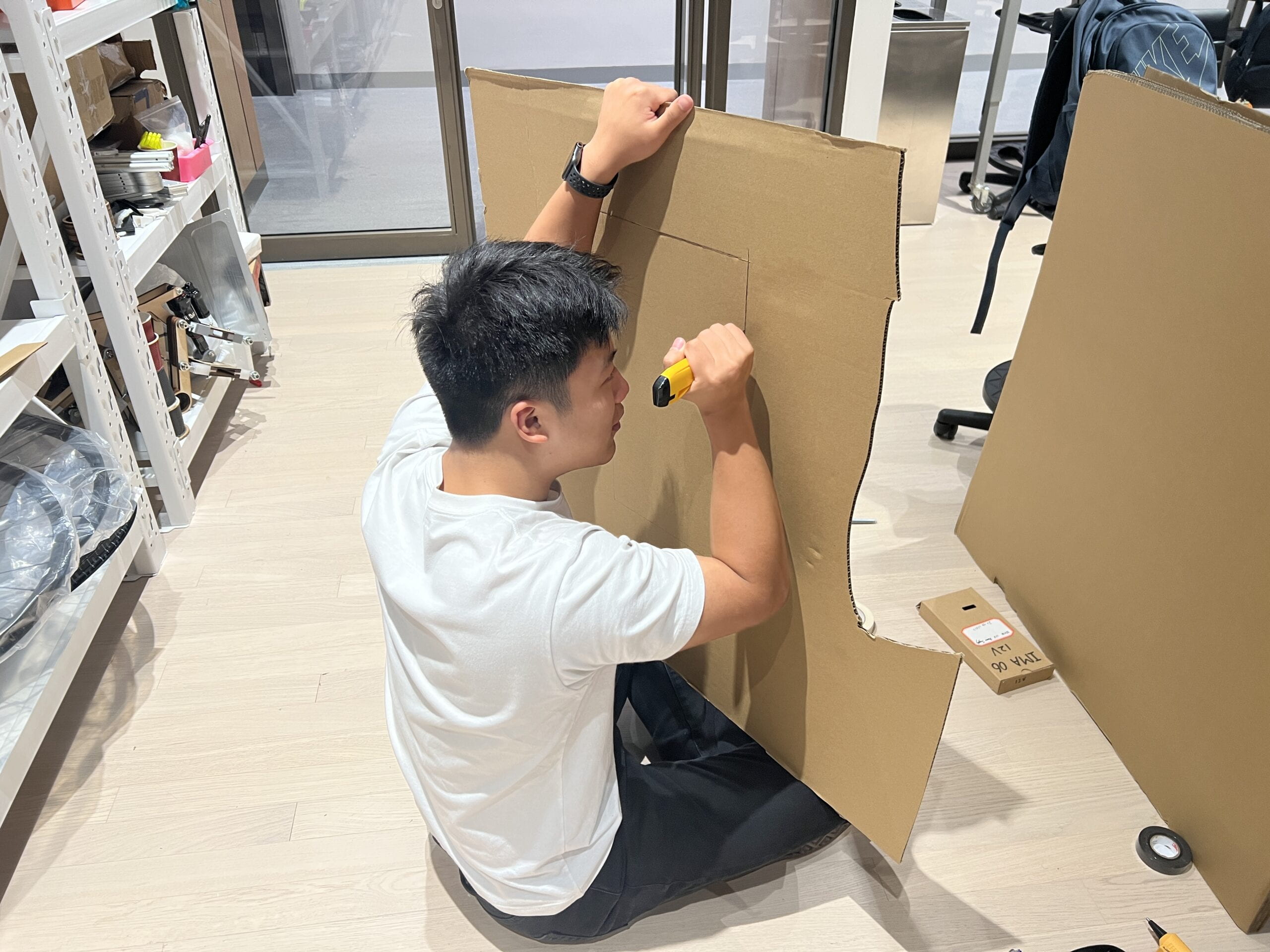
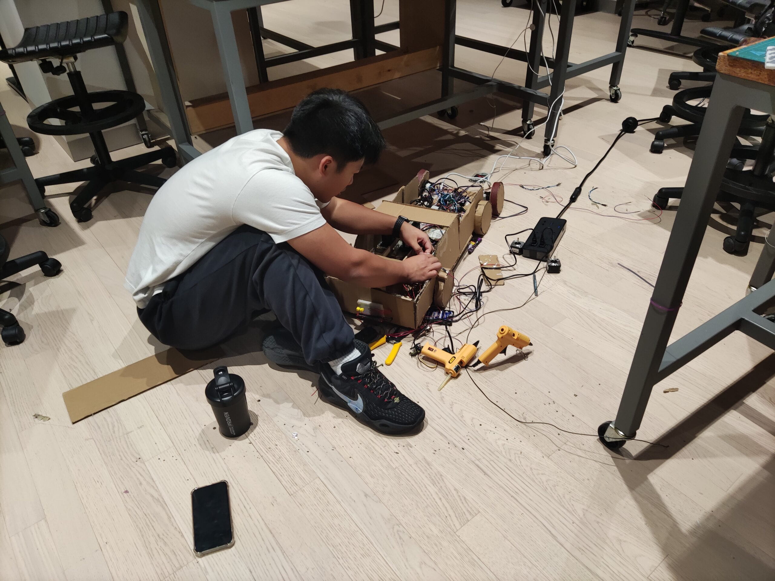
Working hard😄
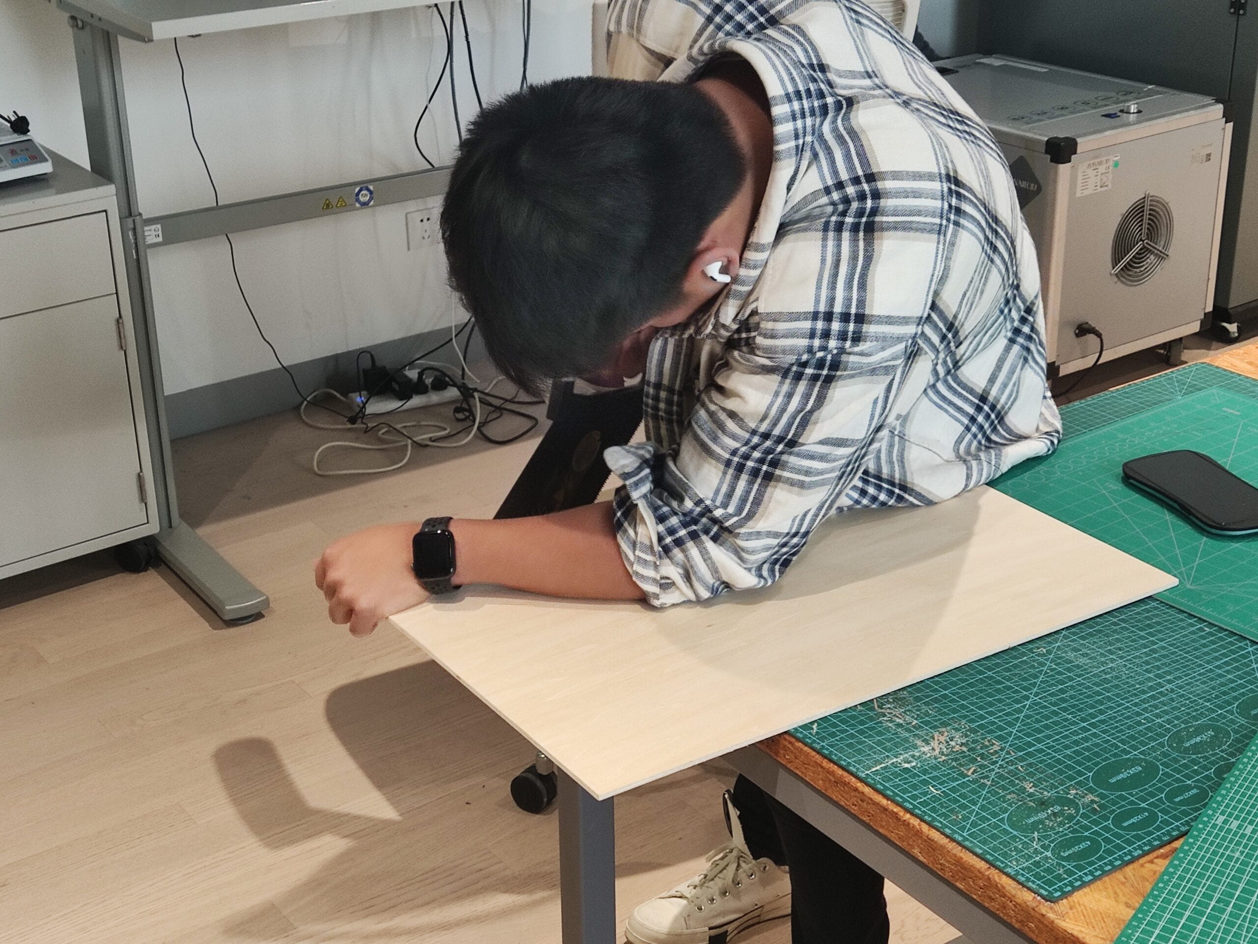
 My bed for two nights T___T
 Thanks for the treats!!!!!

