Assignment 2: Artificial Ecology
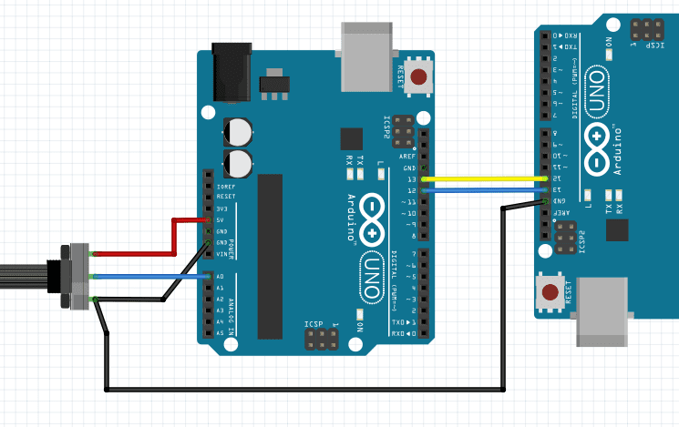
Two Arduinos communicating via I2C Communication
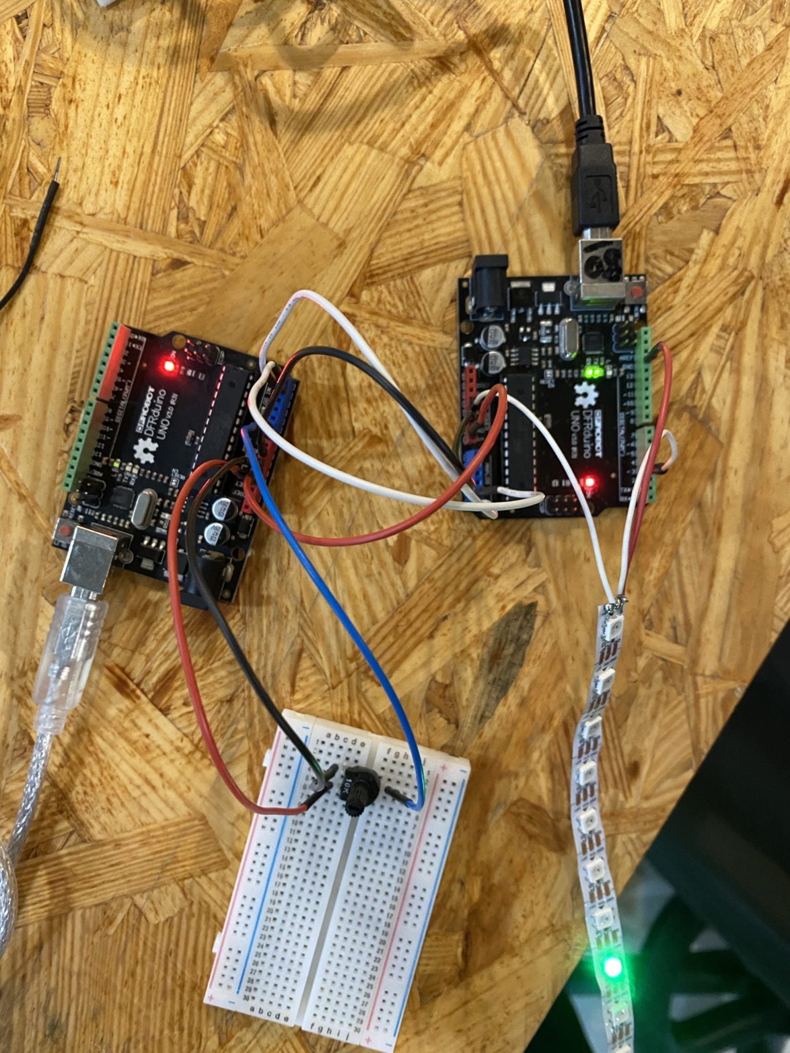
We applied the Wire.h library which is used for I2C communication to connect two Arduinos and used a light strip as the output whose color is changed depending on the potentiometer. The effects we experimented with were NoisePlusPalette, colorTemperature, and Blink from the FastLED example library.
However, in Arduino Uno, to apply the I2C communication protocol, we can only utilize Analog pin 4(A4) as the data line and Analog pin 5(A5) as the clock line. This method limits the connection just to two Arduinos, so we realized we needed to find another way for multiple Arduinos to communicate with each other.
Master Code:
//Code for the Master board
#include<Wire.h>//This library is used for I2C communication
int x;
int y;
void setup() {
Wire.begin();
Serial.begin(9600);
}
void loop() {
x = analogRead(A0);//Reading value from Potentiometer
y = map(x,0,1023,0,255);
Wire.beginTransmission(9);//9 here is the address of the slave board
Wire.write(y);
Wire.endTransmission();
Serial.print(y);
delay(1000);
}
Slave Code:
//Code for the slave board
#include<Wire.h>
#include <FastLED.h>
#define NUM_LEDS 10
int x;
//#define DATA_PIN 3
#define LED_PIN 3
#define CLOCK_PIN 13
#define MAX_BRIGHTNESS 164 // Thats full on, watch the power!
#define MIN_BRIGHTNESS 32 // set to a minimum of 25%
int delayValue = 50;
CRGB leds[NUM_LEDS];
#define COLOR_ORDER RGB
#define LED_TYPE WS2811
void setup() {
pinMode (13, OUTPUT);//Connect LED to pin 13
Wire.begin(9);//9 here is the address(Mentioned even in the master board code)
Wire.onReceive(receiveEvent);
delay(3000); // in case we do something stupid. We dont want to get locked out.
LEDS.addLeds<LED_TYPE, LED_PIN, COLOR_ORDER>(leds, NUM_LEDS).setCorrection(TypicalLEDStrip);
FastLED.setBrightness(MAX_BRIGHTNESS);
Serial.begin(9600);
// FastLED.addLeds<NEOPIXEL, DATA_PIN>(leds, NUM_LEDS);
}
void receiveEvent(int bytes) {
x = Wire.read();//Receive value from master board
Serial.print(x);
}
int mappedHue;
for(int i = 0; i < NUM_LEDS; i++) {
mappedHue = x;
// Set the i’th led to the chosen colour
leds[i] = CHSV(mappedHue, 255, 255);
// Show the leds
FastLED.show();
// now that we’ve shown the leds, reset the i’th led to black
leds[i] = CRGB::Black;
// Wait a little bit before we loop around and do it again
delay(delayValue);
}
for(int i = NUM_LEDS-1; i >= 0; i–) {
// mappedHue = map(x, 0, 1023, 0, 255);
mappedHue = x;
// Set the i’th led to the chosen colour
leds[i] = CHSV(mappedHue, 255, 255);
// Show the leds
FastLED.show();
// now that we’ve shown the leds, reset the i’th led to black
leds[i] = CRGB::Black;
// Wait a little bit before we loop around and do it again
delay(delayValue);
}
}
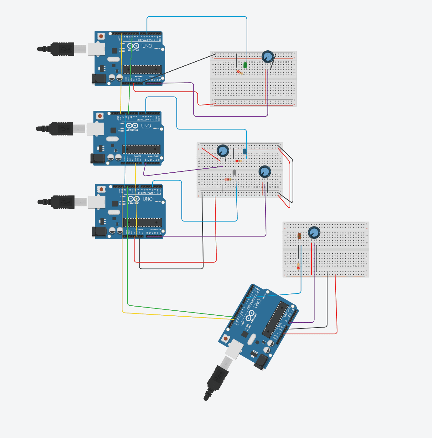
Four Arduinos Communicating via Software Serial Connection
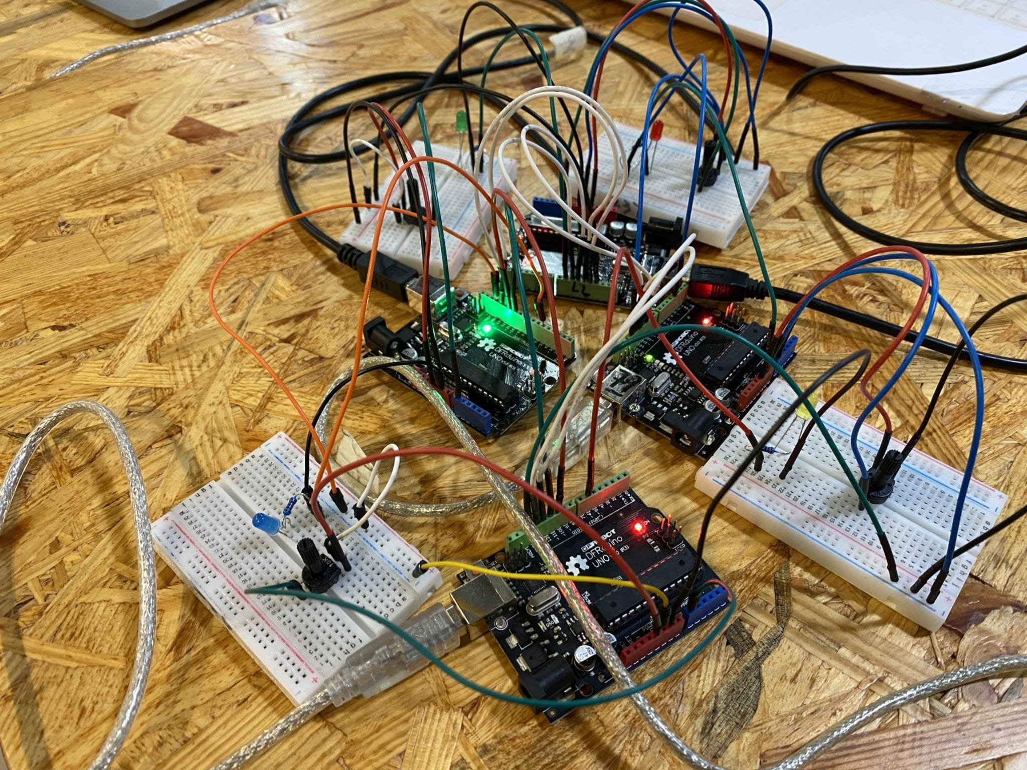
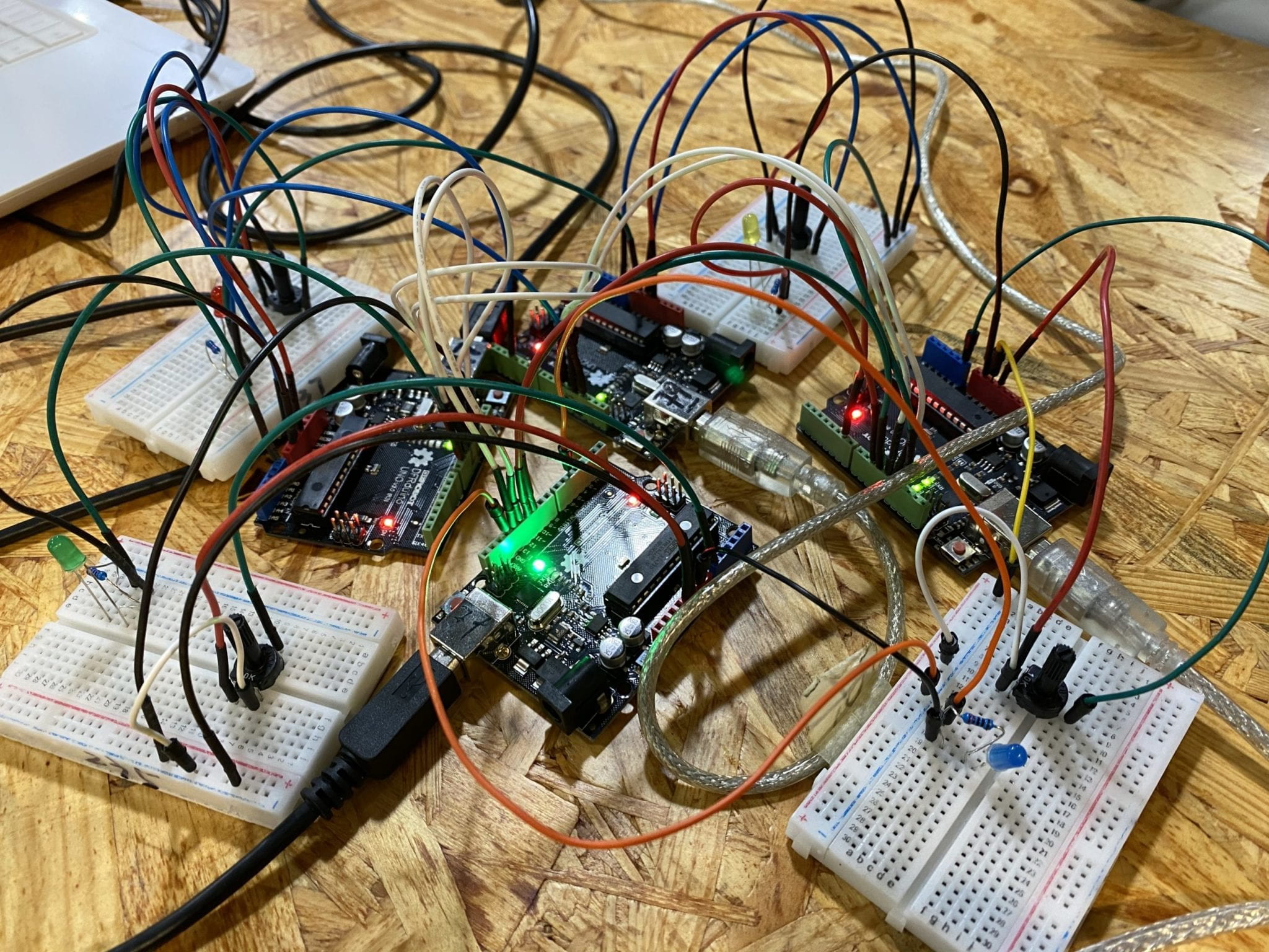
We discovered that this method allows us to define multiple digital pins as RX and TX, (we used pins 10, 11, 12, 13 repeatedly) allowing us to connect the four Arduinos together. In this case, each Arduino board becomes both master and slave.
For this “Artificial Ecology”, we spent a tremendous amount of time on figuring out how SoftwareSerial Library works and debugging. Each time we added a new Arduino board, the previous mechanism stopped working. So instead of using different sensors and outputs, we only built the basic architecture of this “Artificial Ecology” with potentiometers and LEDs.
Explanation of key functions
- serial.listen()
Because each Arduino acts both as a sender and receiver, we need to specify in the code when the Arduino should start listening for information, and from which port. This line goes at the beginning of each section of the slave code. - serial.isListening()
This line returns a boolean reflecting whether or not the software serial port is listening for data. We used this in an if statement in the slave code, to say while there is data coming in, read it, and then send it to the hardware serial port via serial.parseInt(), and serial.print(). - serial.parseInt()
Returns number values of argument from an analog input (in our case the potentiometer)
Code for the First Arduino:
#include <SoftwareSerial.h> //We are using software serial so as not to conflict with serial download and monitor
SoftwareSerial mySerial(12,13); // RX, TX
SoftwareSerial mySerial4(10,11); // RX, TX
int x;
int testvalue4 = 0;
int LEDpin = 5;
void setup() {
Serial.begin(9600);
mySerial.begin(9600);
mySerial4.begin(9600);
pinMode(LEDpin,OUTPUT);
}
void loop() {
//first master
mySerial.listen();
x = map(analogRead(A0),0,1023,0,255);
mySerial.print(x);
Serial.println(x);
mySerial.print( ” “);
delay(100);
//fourth slave
mySerial4.listen();
if(mySerial4.isListening()){
while (mySerial4.available() == 0) { }
testvalue4 = mySerial4.parseInt();
Serial.println(testvalue4);
Serial.print(” “);
if(testvalue4 >= 100){
digitalWrite(LEDpin,HIGH);
}else{
digitalWrite(LEDpin,LOW);
}
delay(200);
}
}
Code for the Second Arduino:
#include <SoftwareSerial.h> //using software serial so as not to conflict with serial download
SoftwareSerial mySerial(12,13); // RX, TX
SoftwareSerial mySerial2(10,11);
/// this sketch is the receiver for green led, master for red led.
int testvalue = 0;
int LEDpin = 9;
int y;
void setup() {
mySerial.begin(9600); //setup software serial
mySerial2.begin(9600);
Serial.begin(9600); //setup serial monitor
pinMode(9,OUTPUT);
}
void loop() {
// receiver code here
mySerial.listen();
if(mySerial.isListening()){
while (mySerial.available() == 0) { }
testvalue = mySerial.parseInt();
//print received values to serial monitor
Serial.println(testvalue);
Serial.println(” “); // print tab for readability
// Serial.println(potpinValue);
if(testvalue >= 125){
digitalWrite(9,HIGH);
}else{
digitalWrite(9,LOW);
}
delay(200);
}
//// master code for red led here
mySerial2.listen();
y = map(analogRead(A0),0,1023,0,255);
mySerial2.print(y);
Serial.println(y);
mySerial2.print(” “);
delay(200);
}
Code for the Third Arduino:
#include <SoftwareSerial.h> //using software serial so as not to conflict with serial download
// third slave board
SoftwareSerial mySerial2(10,11);
SoftwareSerial mySerial3(12,13);
/// this sketch is the receiver for red led, master for yellow led.
int testvalue2 = 0;
int LEDpin = 3;
int y;
void setup() {
//setup software serial
mySerial3.begin(9600);
mySerial2.begin(9600);
Serial.begin(9600); //setup serial monitor
pinMode(LEDpin,OUTPUT);
}
void loop() {
mySerial2.listen();
if(mySerial2.isListening()){
while (mySerial2.available() == 0) { }
testvalue2 = mySerial2.parseInt();
// receiver code here
//print received values to serial monitor
Serial.println(testvalue2);
Serial.print(” “); // print tab for readability
if(testvalue2 >= 125){
digitalWrite(LEDpin,HIGH);
}else{
digitalWrite(LEDpin,LOW);
}
delay(200);
}
////// master code for yellow led here
mySerial3.listen();
y = map(analogRead(A0),0,1023,0,255);
mySerial3.print(y);
Serial.println(y);
mySerial3.print(” “);
delay(200);
}
Code for the Fourth Arduino:
#include <SoftwareSerial.h> //using software serial so as not to conflict with serial download
// forth slave board
SoftwareSerial mySerial3(12,13);
SoftwareSerial mySerial4(10,11);
/// this sketch is the receiver for yellow led, master for blue led.
int testvalue3 = 0;
int LEDpin = 6;
int y;
void setup() {
//setup software serial
mySerial4.begin(9600);
mySerial3.begin(9600);
Serial.begin(9600); //setup serial monitor
pinMode(LEDpin,OUTPUT);
}
void loop() {
mySerial3.listen();
if(mySerial3.isListening()){
while (mySerial3.available() == 0) { }
testvalue3 = mySerial3.parseInt();
// receiver code here
//print received values to serial monitor
Serial.println(testvalue3);
Serial.print(” “); // print tab for readability
if(testvalue3 >= 125){
digitalWrite(LEDpin,HIGH);
}else{
digitalWrite(LEDpin,LOW);
}
delay(200);
}
////// master code for blue led here
mySerial4.listen();
y = map(analogRead(A0),0,1023,0,255);
mySerial4.print(y);
Serial.println(y);
mySerial4.print(” “);
delay(200);
}
Reference:
http://designbuildcode.weebly.com/software-serial-two-arduinos.html
https://www.arduino.cc/en/Reference/softwareSerial
https://www.arduino.cc/en/Tutorial/LibraryExamples/TwoPortReceive
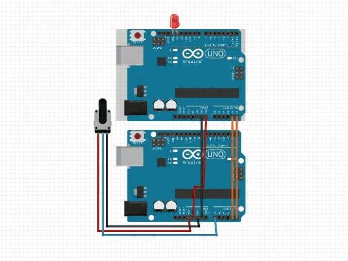
TinkerCad Schematic
Reflection Summary
There is a transition from an object-oriented to a systems-oriented culture. In a system-oriented culture, technological shifts change the way we view and define art. Instead of ideology, technology allows us to focus on the expression of information through the context of systems, which encompass all living situations, activities, and environments. In a system-oriented culture, art has no boundary, no limit, no fixed rules, and no visual concerns. The output or result of art is equally important to the process and techniques. Art no longer resides in material entities, but in human performance, interaction, experience, and relationships with the environment.