Week 02 Lab

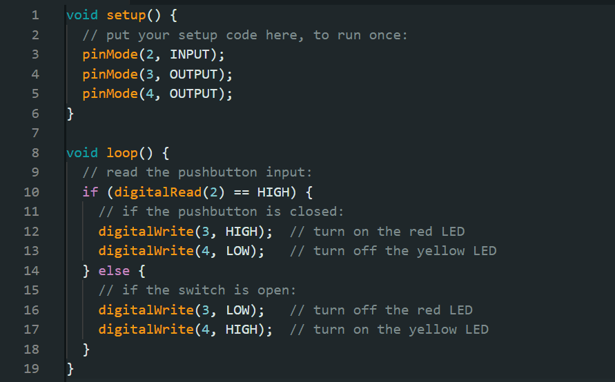
Lab: Digital Input and Output with an Arduino
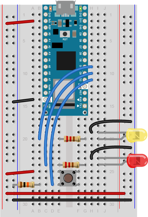
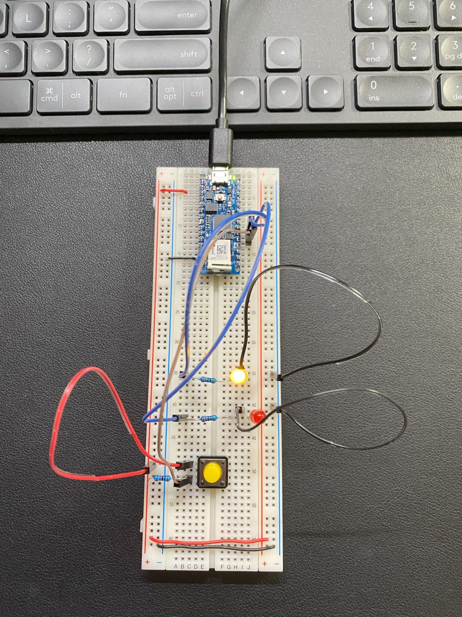
Code:


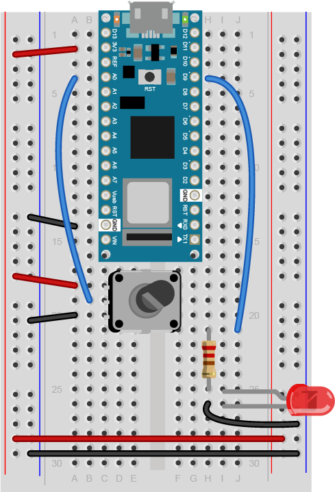
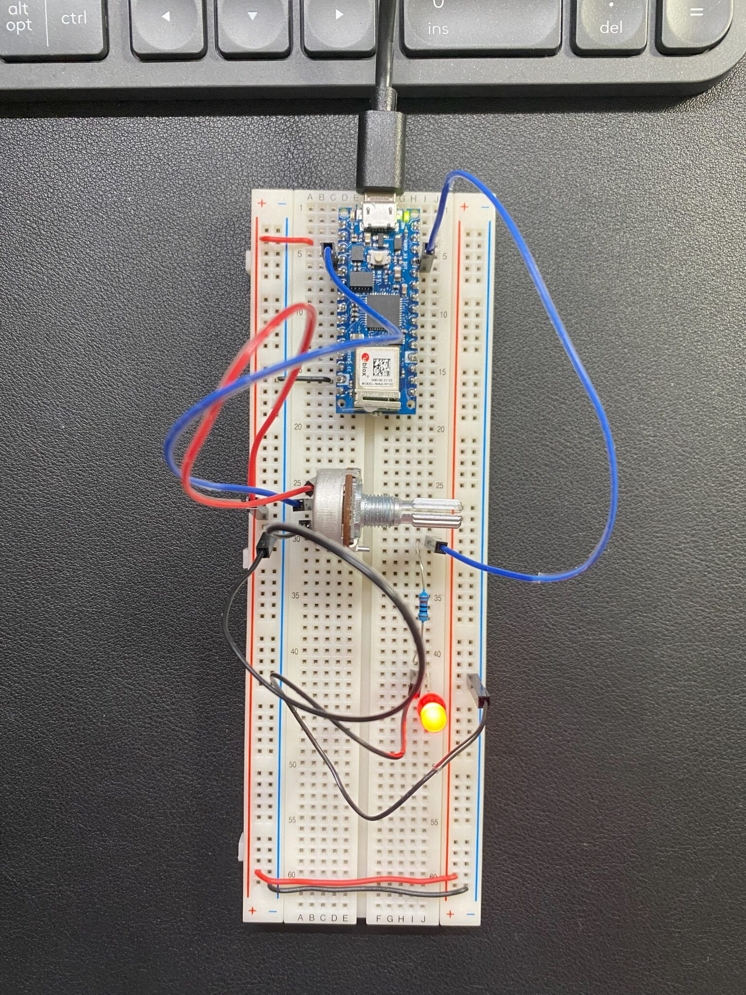
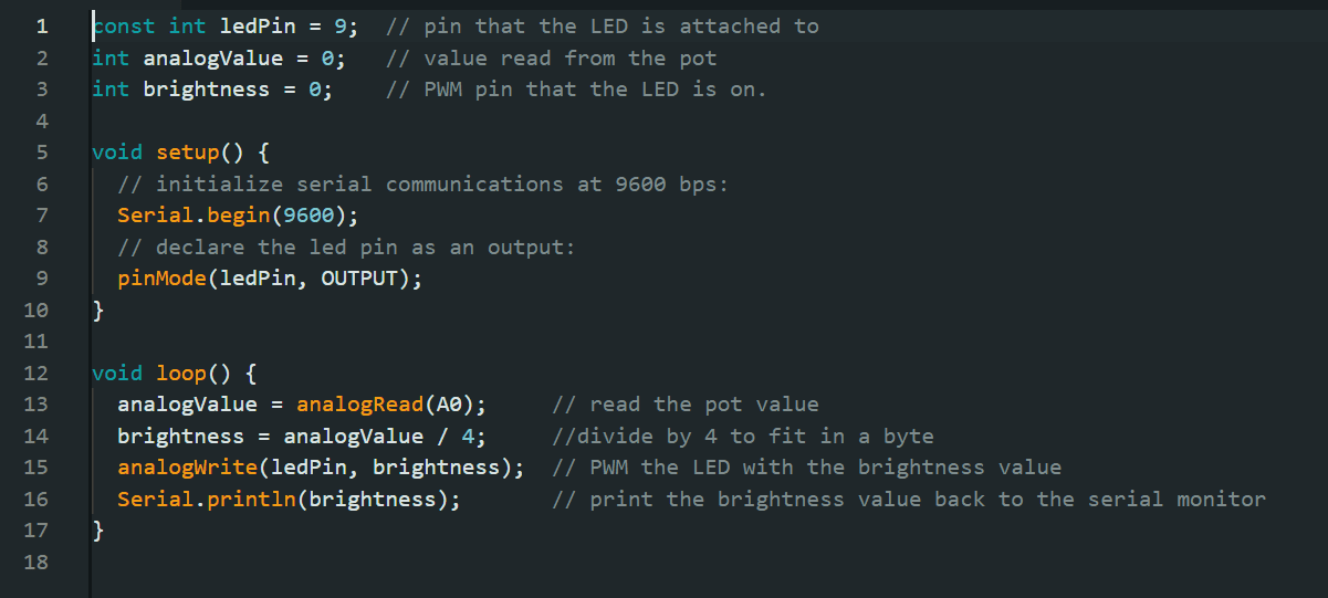
Lab: Analog In with an Arduino

Code:

Notes:

The ADC in the Arduino can read the input voltage at a resolution of 10 bits. That’s a range of 1024 points. The microcontroller makes analog and digital conversions, converting 3.3V to a value of 0 to 1023. So on the serial monitor, we should get a value of 0 to 1023 from the potentiometer. 

The analog value is divided by 4 to get it into a range from 0 to 255. Because, Bytes take up 8 bits, and can therefore store 28 or 256 different values, from 0 to 255. The highest value in this case brightness should be 255. 


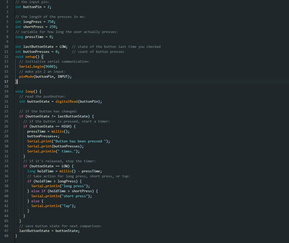
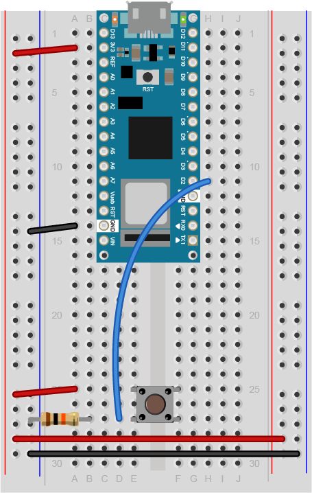
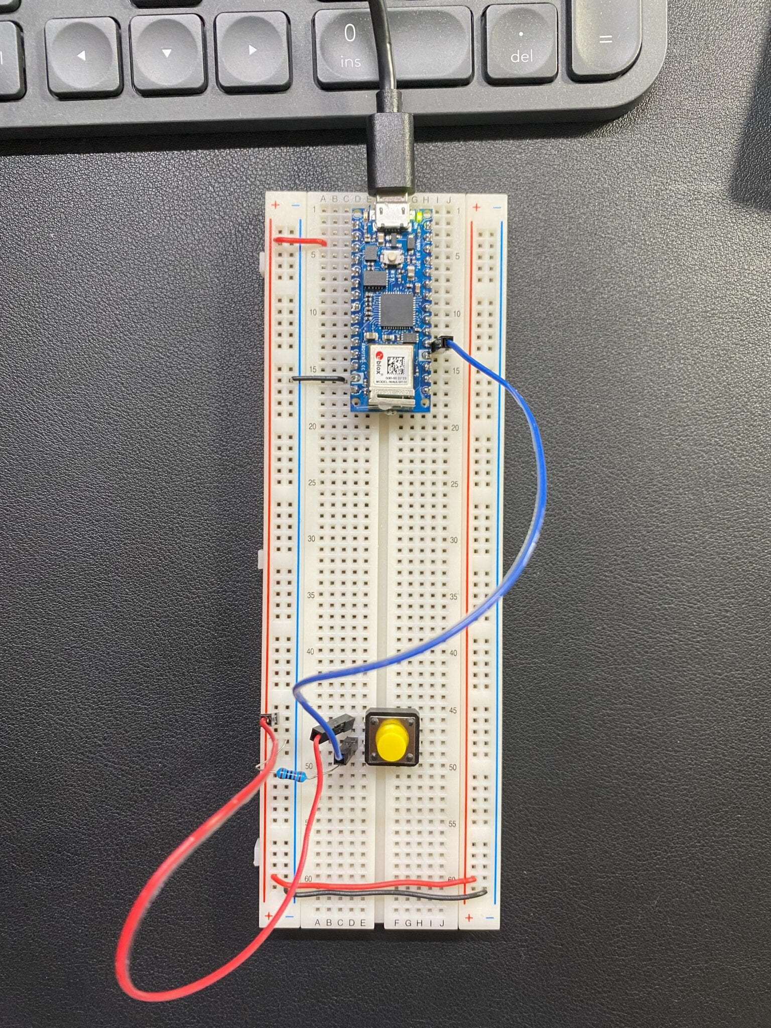
Lab: Sensor Change Detection

  1. Button (Count Button Presses, Long & Tap &Short Presses) 

Breadboard view of an Arduino Nano connected to a pushbutton. The +5 volts and ground pins of the Arduino are connected by red and black wires, respectively, to the left side rows of the breadboard. +5 volts is connected to the left outer side row (the voltage bus) and ground is connected to the left inner side row (the ground bus). The side rows on the left are connected to the side rows on the right using red and black wires, respectively, creating a voltage bus and a ground bus on both sides of the board. The pushbutton is mounted across the middle divide of the solderless breadboard. A 10-kilohm resistor connects from the same row as pushbutton's bottom left pin to the ground bus on the breadboard. There is a wire connecting to digital pin 2 from the same row that connects the resistor and the pushbutton. The top left pin of the pushbutton is connected to +3.3V.

Code:

Leave a Reply

Your email address will not be published. Required fields are marked *