Cloudy with a Chance of Servos – Daniel Woc – Rodolfo Cossovich
Context and Significance
After analyzing Andrea Bravo’s No Territorio and reading short stories for my Group Project presentation, I would say that my definition of interaction has expanded from a concept of utility and assistance to one of creativity and learning. To me, interaction now entails the reciprocal action between two parties and the influence they have over each other. This action and influence must result from a conversation that does not necessarily have to be two-sided and can stray from a purely practical purpose. In the Group Project, I showed an interaction based on practicality and now want to show an interaction based on creativity with this Midterm Project. I concluded that creating a conversation between an individual and art would best suit my aspirations for this project. Furthermore, I believe that art is for everyone, and my project should be no different.
Conception and Design
I had originally intended to create the project I had ideated in the proposal phase. However, when my partner, Luciana, and I discussed our ideas, we decided to combine them and create an art installation that would move according to the user’s position, immediately allowing us to identify what type of interaction we were going to implement and the feedback that needed to be shown in our project.
In order to properly create this “conversation” between the installation and the individual, I found myself naturally drawn to using distance sensors as the installation’s “eyes” and using that as the medium for the interaction. I don’t think that any other sensor would’ve been as practical or appropriate for the project since we wanted to emphasize the position of the user in relation to our project. To convey motion, we found micro servo motors to be the best, as their lightweight and simplicity would help us achieve what we wanted. We originally had planned to use 32, but due to complications, we reduced the amount to 16. Using DC or stepper motors would be too complicated for the simple motion we wanted to show.
Now that we identified how our project was going to interact with the user, we needed to find the best way to adapt it to the physical world. My partner and I concluded that hanging our project from the ceiling would be the best as the interaction between the user and our project would be unique since one would have to walk under our project. After deciding this, we found that modeling our project after a cloud would allow us to deliver an interesting visual message. Furthermore, this would also simulate what walking under a cloud could feel like!
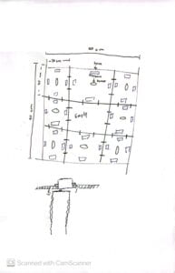
In order to assemble our project and be able to hang it, my partner and I saw it fit to use cardboard matrices that would each hold a distance sensor and two (originally four) servo motors. This little setup is what I like to call a “module,” and our project will use eight of them and an additional empty one for the center.
Here’s a sketch of our project!
Fabrication and Production
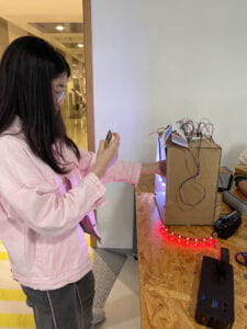
For our User Testing Session, we decided to create a small-scale version of our project. In a small box, we demonstrated a simplified concept of our project that scaled down the size of our final iteration. We used two distance sensors with two servo motors each to represent the different modules we would have in our final version. However, looking back at this phase, it might have been better to create a piece of our final project instead of a miniature version in order to streamline our production process of the physical aspects of our project. At this stage of our fabrication process, we faced some learning curves, mainly the challenges of figuring out the code we needed and how we needed to structure it in order for it to accomplish what we wanted.
When it came to creating our final project, it truly was a journey. We came across a lot of learning curves, such as figuring out the structure our project needed if we wanted to hang it and the challenges that arose from using 32 servo motors. In order to hang our project, our professors suggested we use wooden pieces for support and attach crew hooks to them. In addition to this, we sharpened wooden dowels and used them in addition to hot glue when connecting our modules to each other. Another professor also suggested methods for securing the servos and ensuring that they don’t fall, which we incorporated into our project. Below is a picture of the first iteration of our final project.
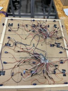
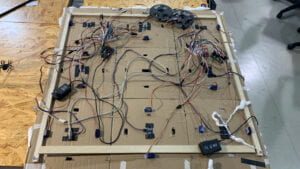
This version of our project didn’t work, presumably due to the insufficient power supply, too many servo motors, or perhaps a simple wrong connection. Nonetheless, we didn’t let this setback bring us down, and we still wanted to finish our project. By reducing the number of servos by half and working in a more methodical manner, we reduced the space for errors. We also replaced servos that were not working or were 360 and drove our project bonkers. A week later, my partner and I were able to complete our project.
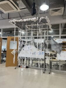
Here’s a quick list of the materials we used for this project!
16 servo motors
16 metal pieces (I’m not sure how else to describe them)
24 sharpened wood dowels
9 30cm x 30cm cardboard pieces
8 distance sensors
4 80cm wooden pieces
4 metal screw hooks
2 WS2812B LED strips
2 220 Ω resistors
2 470 F capacitors
2 Arduinos
Wires
Hot Glue
Cotton
Cotton Strings
I worked on the circuitry and coding of our project while my partner focused on the physical aspects of it. Here is the code of our project!
#include <Servo.h>
#include <FastLED.h>
#include <NewPing.h>

//sensor defines
#define PING_PIN1 3  // attach pin D2 Arduino to pin Echo of HC-SR04
#define PING_PIN2 4  //attach pin D3 Arduino to pin Trig of HC-SR04
#define PING_PIN3 5
#define PING_PIN4 6
#define MAX_DISTANCE 400

//sonar objects
NewPing sonar1(PING_PIN1, PING_PIN1, MAX_DISTANCE);
NewPing sonar2(PING_PIN2, PING_PIN2, MAX_DISTANCE);
NewPing sonar3(PING_PIN3, PING_PIN3, MAX_DISTANCE);
NewPing sonar4(PING_PIN4, PING_PIN4, MAX_DISTANCE);

//LED defines
#define DATA_PIN    2
//#define CLK_PIN   4
#define LED_TYPE    WS2812B
#define COLOR_ORDER GRB
#define NUM_LEDS    150
#define BRIGHTNESS  255

//servo variables
int pos1 = 0;
int pos2 = 0;
int pos3 = 0;
int pos4 = 0;

//time variables
long startTime1 = -1;
long startTime2 = -1;
long startTime3 = -1;
long startTime4 = -1;

//segments for LED variables
int b1 = 131;
int e1 = 150;
int b2 = 122;
int e2 = 131;
int b3 = 104;
int e3 = 122;
int b4 = 77;
int e4 = 104;
int b5 = 70;
int e5 = 77;
int b6 = 60;
int e6 = 70;

//servo objects
Servo myservo1;
Servo myservo2;
Servo myservo3;
Servo myservo4;

//LED objects
CRGB leds[NUM_LEDS];

void setup() {
  FastLED.addLeds<LED_TYPE,DATA_PIN,COLOR_ORDER>(leds, NUM_LEDS)
    .setCorrection(TypicalLEDStrip)
    .setDither(BRIGHTNESS < 255);
  FastLED.setBrightness(BRIGHTNESS);

  myservo1.attach(9);
  myservo2.attach(10);
  myservo3.attach(11);
  myservo4.attach(12);

  Serial.begin(9600);
}

void loop() {
  sensor1();
  sensor2();
  sensor3();
  sensor4();

  if(sonar1.ping_cm() <= 80)
  {
    startTime1 = millis();

    if(startTime1 != -1)
    {
      moveMod1();
    }

    pride(b1, e1);
    pride(b6, e6);
    FastLED.show();
  }

  if(sonar2.ping_cm() <= 80)
  {
    startTime2 = millis();

    if(startTime2 != -1)
    {
      moveMod2();
    }
    pride(b2, e2);
    pride(b5, e5);
    FastLED.show();
  }

  if(sonar3.ping_cm() <= 80)
  {
    startTime3 = millis();

    if(startTime3 != -1)
    {
      moveMod3();
    }

    pride(b3, e3);
    FastLED.show();
  }

  if(sonar4.ping_cm() <= 80)
  {
    startTime4 = millis();

    if(startTime4 != -1)
    {
      moveMod4();
    }

    pride(b4, e4);
    FastLED.show();
  }

}

void sensor1() {
  delay(50);                // Wait 50ms between pings (about 20 pings/sec). 29ms should be the shortest delay between pings.
  Serial.print("Ping1: ");
  Serial.print(sonar1.ping_cm()); // Send ping, get distance in cm and print result (0 = outside set distance range)
  Serial.println("cm");
}

void sensor2() {
  delay(50);               // Wait 50ms between pings (about 20 pings/sec). 29ms should be the shortest delay between pings.
  Serial.print("Ping2: ");
  Serial.print(sonar2.ping_cm()); // Send ping, get distance in cm and print result (0 = outside set distance range)
  Serial.println("cm");
}

void sensor3(){
  delay(50);                 // Wait 50ms between pings (about 20 pings/sec). 29ms should be the shortest delay between pings.
  Serial.print("Ping3: ");
  Serial.print(sonar3.ping_cm()); // Send ping, get distance in cm and print result (0 = outside set distance range)
  Serial.println("cm");
}

void sensor4(){
  delay(50);                 // Wait 50ms between pings (about 20 pings/sec). 29ms should be the shortest delay between pings.
  Serial.print("Ping4: ");
  Serial.print(sonar4.ping_cm()); // Send ping, get distance in cm and print result (0 = outside set distance range)
  Serial.println("cm");
}

void moveMod1() {
  if(millis() - startTime1 < 100)
  {
      if(millis() % 360 < 1800)
      {
        pos1 = millis() % 180;
      }
      else
      {
        pos1 = 180 - millis() % 180;
      }
      myservo1.write(pos1);
  }
}

void moveMod2() {
  if(millis() - startTime2 < 100)
  {
      if(millis() % 360 < 1800)
      {
        pos2 = millis() % 180;
      }
      else
      {
        pos2 = 180 - millis() % 180;
      }
      myservo2.write(pos2);
  }
}

void moveMod3() {
  if(millis() - startTime3 < 100)
  {
      if(millis() % 360 < 1800)
      {
        pos3 = millis() % 180;
      }
      else
      {
        pos3 = 180 - millis() % 180;
      }
      myservo3.write(pos3);
  }
}

void moveMod4() {
  if(millis() - startTime4 < 100)
  {
      if(millis() % 360 < 1800)
      {
        pos4 = millis() % 180;
      }
      else
      {
        pos4 = 180 - millis() % 180;
      }
      myservo4.write(pos4);
  }
}

void whiteMod(int b, int e) {
  for (int i = b; i <= e; i++) {
    leds[i] = CRGB::WhiteSmoke;
  }
  FastLED.show();
}

void pride(int b, int e)
{
  static uint16_t sPseudotime = 0;
  static uint16_t sLastMillis = 0;
  static uint16_t sHue16 = 0;

  uint8_t sat8 = beatsin88( 87, 220, 250);
  uint8_t brightdepth = beatsin88( 341, 96, 224);
  uint16_t brightnessthetainc16 = beatsin88( 203, (25 * 256), (40 * 256));
  uint8_t msmultiplier = beatsin88(147, 23, 60);

  uint16_t hue16 = sHue16;//gHue * 256;
  uint16_t hueinc16 = beatsin88(113, 1, 3000);

  uint16_t ms = millis();
  uint16_t deltams = ms - sLastMillis ;
  sLastMillis  = ms;
  sPseudotime += deltams * msmultiplier;
  sHue16 += deltams * beatsin88( 400, 5,9);
  uint16_t brightnesstheta16 = sPseudotime;

  for( uint16_t i = b ; i < e; i++) {
    hue16 += hueinc16;
    uint8_t hue8 = hue16 / 256;

    brightnesstheta16  += brightnessthetainc16;
    uint16_t b16 = sin16( brightnesstheta16  ) + 32768;

    uint16_t bri16 = (uint32_t)((uint32_t)b16 * (uint32_t)b16) / 65536;
    uint8_t bri8 = (uint32_t)(((uint32_t)bri16) * brightdepth) / 65536;
    bri8 += (255 - brightdepth);

    CRGB newcolor = CHSV( hue8, sat8, bri8);

    uint16_t pixelnumber = i;
    pixelnumber = (NUM_LEDS-1) - pixelnumber;

    nblend(leds[pixelnumber], newcolor, 64);
  }
}
Since we used two Arduinos, the code in each of them is the same, save for a few differences. One of these differences was the definitions of the LED segments. As you may notice, I included two extra variables, b34 and e34. I used these for additional commands when sensor 3 activated, as the layout for the LEDs in the second half was different and needed this modification.
int b1 = 137;
int e1 = 150;
int b2 = 119;
int e2 = 137;
int b3 = 110;
int e3 = 118;
int b4 = 86;
int e4 = 109;
int b34 = 78;
int e34 = 85;
int b5 = 70;
int e5 = 77;
int b6 = 65;
int e6 = 76;
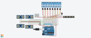
Here is a diagram of our circuit! Bear in mind since we have two identical halves, I only created the diagram for one.
Conclusion
With my midterm project, I aimed to embody the very concept of a conversation between an individual and art through an interaction based on creativity. To represent this and the idea that art is for everyone, I decided to create an interactive art installation that would respond to the user’s movement. I would say that how my audience interacted with my project showed that I accomplished that intention and was able to deliver it creatively. Furthermore, I would say that this interaction effectively demonstrated my definition of interaction as it embodied the idea that interaction can consist of a conversation that does not necessarily have to be practical and can break the boundaries of practicality.
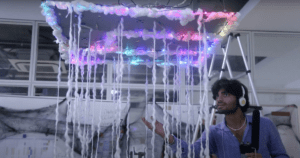
While I did have more time to finish my project, I would have liked to fine-tune some details, such as the decorations and the support of our project. I would say that the failures I encountered in this project have allowed me to push forward despite obstacles and never lose the end in sight. Additionally, I now know that I need to work methodically when approaching circuits and the steps I need to take when working with Arduino. However, I think it’s also important for me to recognize what I learned from my accomplishments, such as thinking out of the box (like learning a neat little trick for controlling multiple servos) and pushing myself to my limits. Nonetheless, I am proud of the project I created, and I will use this as an opportunity to learn for future projects and endeavors.
Annex
Bonus pics!
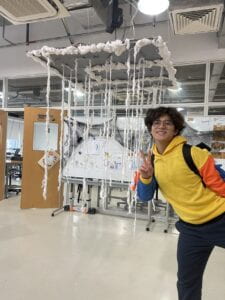
Servotruco in action
