Box of Illusion – Bruce & Kelvin – Prof. Maragret Minskey
Part 1: Conception and Design
1.1: Conception Formation and Primary Research
The concept of my final project is to create an interactive installation called “The Box of Illusion” that combines music, light, and infrastructure to tell a visual story through projected light and shadows. The project draws inspiration from interactive art projects that use light and shadow to convey a sense of change and storytelling. The preparatory research on Ernest Edmonds’ article and the two interactive projects featuring light and shadow influenced my understanding of how to incorporate these elements into my own project.
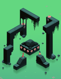
One of the key design decisions informed by my understanding of user interaction was to make the installation collaborative and immersive. Inspired by the game “Monument Valley,” where players interact with the landscape and the music changes accordingly, I decided to create an interaction between the players and the installation. This decision was made to engage the users and allow them to actively participate in shaping the visual and auditory experience. By incorporating Processing and Arduino technologies, I could create a dynamic and responsive environment where users’ actions would influence the changes in the projected visuals and accompanying music.
Another design decision was to construct a concealed black box as the “projector” of the installation. This decision was influenced by the need to create a focused and controlled environment for the projection of light and shadows. By enclosing the light sources and the spinning platform within the box, I could ensure that the projected visuals would be clearly visible and impactful on the external canvas. The concealed nature of the box also adds an element of mystery and intrigue for the users, inviting them to explore and interact with the installation.
Considering the materials for the objects placed on the spinning platform, we decided to use colorful transparent materials such as glass with attached colorful films or transparent plastic. This decision was influenced by the desire to enhance the visual appeal of the shadows created by the objects. The use of colorful transparent materials would add vibrancy and richness to the projected visuals, making the light story more visually captivating for the audience.
Overall, based on our discussion and fabrication we’ve created an immersive, collaborative experience aiming to create a dynamic, engaging, and visually captivating installation for the audience to interact with and experience.
1.2: Design and Integration
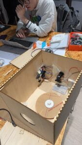
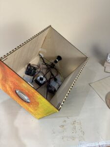
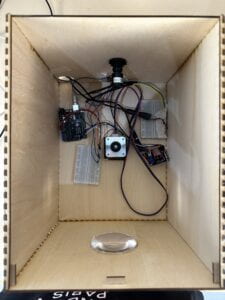
We initially designed the model according to the blueprints we created. We laser cut a box and placed all the connected circuits and power sources inside it. We also created prototypes to simulate the focal length of convex lenses and ensure that the imaging was visible. After user testing, we listened to the advice of different professors, Kevin and Sylvia, and made improvements such as optimizing the layout of the wires, creating a white projection screen for our project, and using materials from the woodworking workshop to make a stand, among others. This series of upgrades made the entire project more complete and user-friendly.
All these upgrade and optimization decisions were aimed at improving the overall completeness, usability, and visual appeal of the project, allowing users to interact with it better and enjoy its visual effects. By listening to user feedback and professor’s suggestions, and making improvements based on actual needs, you have successfully elevated the project to a higher level.
Part 2: Fabrication and Production
We followed the sketch we’ve made initially and finished the first-stage fabrication. Kelvin used the template in the Fabrication Lab and self-designed a box which we might be abele to apply the concave lenses and all the motors into it.
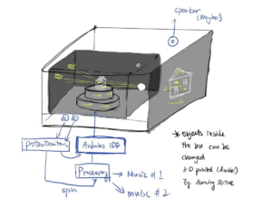
After that, we proceeded to design the most crucial part of the project, which is the design of the rotating platform. We borrowed an external power source and a motor from the Equipment Room to achieve the desired functionality. During the design process, we found that using a spinning potentiometer to control the rotation speed of the platform was not very noticeable or feasible. As a result, we decided to abandon the sliding potentiometer and instead opted for an ultrasonic sensor. This change made the interaction between the users and the project more clear and effective.
Furthermore, Kelvin and I worked together to address the issue of light projection. After discussing various options, we came to the decision to forgo using a projector and instead utilize a 15V light bulb purchased online as our light source. We consulted Professor Andy, who suggested using an external power supply to ensure the safety of the circuit, as the light bulb requires a significant current to operate. Therefore, we incorporated an external power supply and extended the circuit by soldering wires to meet our specific requirements.
To ensure the safety and stability of the circuit, we carefully selected and connected the appropriate wires we soldered it to the light wires. which made the bulb functions well.
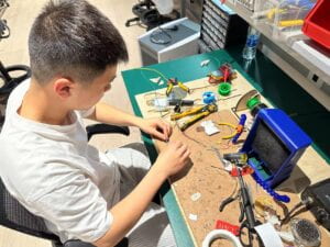
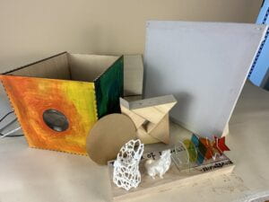
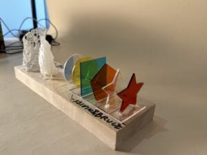
Following that, Kelvin purchased various colors of glass paper online to decorate the transparent pieces of PVC material that we had cut into different shapes. We glued them together to create visually appealing elements. Additionally, I used templates to design two different 3D printing files. These small objects serve as the main interactive components for our project.

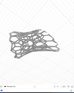
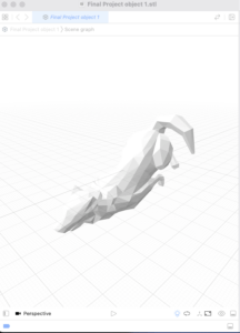
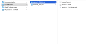
Moreover, we’ve chose two different music to be placed into processing to make the whole user experience more engaging and interactive. When people is in middle distance to the project we provide a more calm music with higher spinning speed, however, when people are close to the project, the processing will play a more nature music as if you are in an enchanted forest. Thus, we can integrate the user experience and let the users have a more solid experience.
Finally, after user testing, we accepted the fellow and professor’s suggestions and built a canvas with a white cape which allows the project to project onto it perfectly. Also, I recycled the wood in the fabrication lab to build a base for our projection machine.
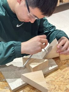
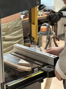
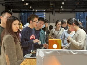
Here’s Our Final Creation!

Part 3: Conclusions
Throughout the course of our project, our primary goal was to create an interactive installation that utilized light and shadow to convey a sense of storytelling and engage the audience. We aimed to incorporate music, sensing devices, and projection to create a dynamic and immersive experience.
In terms of achieving our stated goals, we are pleased with the outcome of our project. The use of light, shadow, and interactive elements successfully conveyed a narrative and captivated our audience. We observed that our audience engaged with the project by actively placing objects on the spinning platform, manipulating the light and shadow projections, and experiencing the changing atmosphere created by the accompanying music.
Our project results align with our definition of interaction as we intended to create an experience where the audience actively influenced the changes in the art object. By incorporating interactive elements such as the spinning platform and allowing users to manipulate the visuals and music, we provided a space for the audience to actively participate in shaping the narrative and atmosphere of the installation.
Given more time, we would have further refined the technical aspects of our project. We would have explored more advanced programming techniques to enhance the responsiveness and interactivity of the system. Additionally, we would have focused on creating a more seamless and intuitive user interface to ensure a smoother interaction between the audience and the installation. Indeed, all the setbacks and failures have provided valuable learning experiences. We encountered challenges in finding the optimal control method for the spinning platform and had to adapt our approach by using an ultrasonic sensor instead of a potentiometer. These setbacks taught us the importance of flexibility and problem-solving. Also, the changes that we made on our sketches, gradually altering the project into a down-to-ground thing is absolutely a worth reflecting process.
The main take away for me for the whole semester after taking the INTERACTION LAB class is to have more VIBRANT mind which we are willing to come up with crazy thoughts and turn it into reality.
ALWAYS START YOUR INITIATIVE EARLY AND EMBRACE CHALLENGES!
Appendix
- Arduino Codes
#include <AccelStepper.h>

int DIR_PIN = 2;

int STEP_PIN = 3;

int EN_PIN = 4;

int counter = 0;

int lastD;

// Define a stepper and the pins it will use

// AccelStepper::DRIVER means a stepper driver (with step and direction pins)

AccelStepper stepper(AccelStepper::DRIVER, STEP_PIN, DIR_PIN);

// defines ultrasonic pins numbers

const int trigPin = 6;

const int echoPin = 5;

// defines variables

long duration;

int distance;

void setup() {

 //Ultrasonic Input&Output

 pinMode(trigPin, OUTPUT);  // Sets the trigPin as an Output

 pinMode(echoPin, INPUT);   // Sets the echoPin as an Input

 Serial.begin(9600);

 // Enable the stepper driver by setting the

 // EN pin to LOW

 pinMode(EN_PIN, OUTPUT);

 digitalWrite(EN_PIN, LOW);

 // The run() function will accelerate up to

 // the speed set here

 stepper.setMaxSpeed(2000);

 // Set the desired constant speed for use with

 // runSpeed()

 stepper.setSpeed(200);

}

void loop() {

 digitalWrite(trigPin, LOW);

 delayMicroseconds(2);

 // Sets the trigPin on HIGH state for 10 micro seconds

 digitalWrite(trigPin, HIGH);

 delayMicroseconds(10);

 digitalWrite(trigPin, LOW);

 // Reads the echoPin, returns the sound wave travel time in microseconds

 duration = pulseIn(echoPin, HIGH);

 // Calculating the distance

 distance = duration * 0.034 / 2;

 // Prints the distance on the Serial Monitor

 // Serial.println(distance);  // Send the distance to the serial port

 Serial.println(distance);

 if (counter % 10 == 0) {

   // Clears the trigPin

   if (abs(lastD - distance) > 0) {

     int speed = constrain(map(distance, 0, 55, 2000, 200), 200, 2000);

     // Set the stepper motor speed

     stepper.setSpeed(speed);

     // Move the stepper motor at the set speed

   }

   lastD = distance;

 }

 stepper.runSpeed();

 counter++;

}
- Processing codes
import processing.serial.*;
Serial serialPort;
int NUM_OF_VALUES_FROM_ARDUINO = 1;  /* CHANGE THIS ACCORDING TO YOUR PROJECT */
/* This array stores values from Arduino */
int arduino_values[] = new int[NUM_OF_VALUES_FROM_ARDUINO];

import ddf.minim.*;

Serial myPort;
Minim minim;
AudioPlayer music1, music2;

void setup() {
  size(400, 400);
  background(255);

  printArray(Serial.list());
  // Open the serial port and set the baud rate to match the Arduino sketch
  serialPort  = new Serial(this, "/dev/cu.usbmodem1101", 9600);

  // Load the music tracks
  minim = new Minim(this);
  music1 = minim.loadFile("music1.mp3");
  music2 = minim.loadFile("music2.mp3");
}

void draw() {
  background(255);
  // receive the values from Arduino
  getSerialData();
  println(arduino_values[0]);
  float distance = arduino_values[0];

  //if (serialPort.available() > 0) {
  //  String distanceString = myPort.readStringUntil('\n');
  //  if (distanceString != null) {
  //    int distance = int(distanceString.trim());

      if (distance > 30) {
        if (!music1.isPlaying()) {
          music1.play();
        }
        if (music2.isPlaying()) {
          music2.pause(); // pause music2 if it is already playing
        }
      } else {
        if (!music2.isPlaying()) {
          music2.play();
        }
        if (music1.isPlaying()) {
          music1.pause(); // pause music1 if it is already playing
        }
      }
    }
  //}
//}

void getSerialData() {
  while (serialPort.available() > 0) {
    String in = serialPort.readStringUntil( 10 );  // 10 = '\n'  Linefeed in ASCII
    if (in != null) {
      print("From Arduino: " + in);
      String[] serialInArray = split(trim(in), ",");
      if (serialInArray.length == NUM_OF_VALUES_FROM_ARDUINO) {
        for (int i=0; i<serialInArray.length; i++) {
          arduino_values[i] = int(serialInArray[i]);
        }
      }
    }
  }
}
Citation:
“This Site Requires JavaScript Enabled.” Printables, www.printables.com/model/386392-low-poly-howling-wolf-20-decorationno-supports-fix. Accessed 15 May 2023.
