Oceanic Explorer
Conception and Design
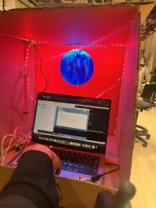
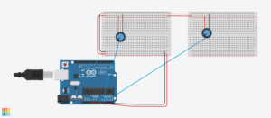
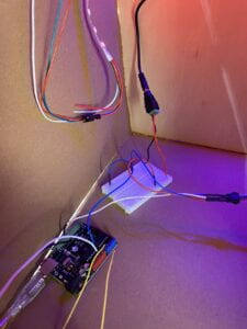
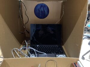
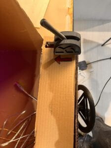
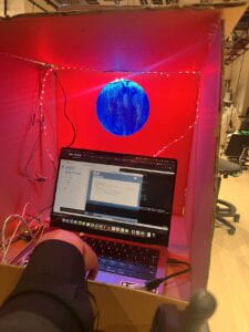
For the conception of our project, we saw that the most successful interactive artifacts were able to capture interaction of multiple senses in simple but effective ways that do not intimidate the human actor. For instance, “Iris” by HYBE Studio, despite being a simple concept, effectively engages the human actor through kinetic and visual interaction. Thus, we decided to use our artifact to encapsulate kinetic, visual, and audible interaction. Our project (see below)is an immersive submarine experience which captures kinetic interaction through interaction with a wheel (potentiometer) and lever (slide potentiometer), visual interaction through changing depth (Processing display) and lights (Neopixel LED strips), and audible interaction through a beeping sonar and monster sounds (Processing sketch).
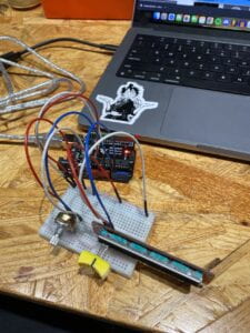
During the user testing (see above), we only had two potentiometers (depth working, speed not), and our display was just an interactive blue screen with the sole working potentiometer. the feedback we received revolved around making the display more visually stimulating with other designs such as fish, radar, etc, and making the entire artifact more complex, which would create more of a background story that would hint towards the human actor that the artifact is meant to be an interactive submarine experience. Using this feedback, we decided to create in our Processing display a radar and a monster that is only visible at deeper depths. They were ultimately effective as they created more of an immersive experience than just a changing blue screen.
Fabrication and Design
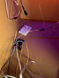
In the beginning, we wanted to capture kinetic interaction through the use of accelerometers instead of potentiometers because they allowed for more kinetic freedom. However, execution was a problem, since maintaining a working circuit with the accelerometers and incorporating code that was necessary for accelerometers into Arduino and having it readable for Processing were difficult. Furthermore, the accelerometers provided reliable data for our project. Thus, we opted to use the potentiometers, since they were more reliable in providing accurate data for our sketches, and they were able to stay intact with our circuit better than the accelerometers (however, not completely successful, since our wheel would weigh our potentiometer down enough where it would sometimes fall out of our circuit).
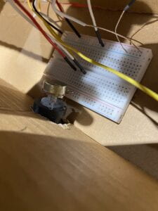
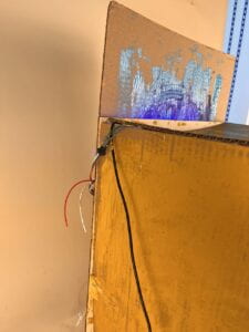
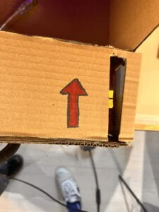
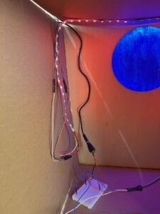
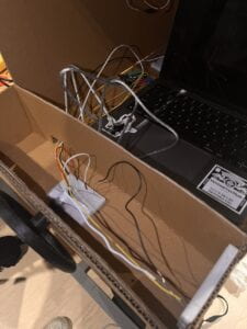
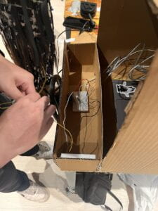
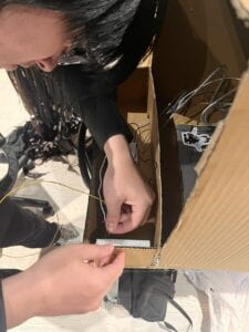
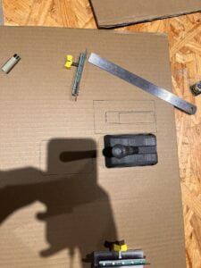
Most importantly, they were still able to provide a satisfactory kinetic experience. We also incorporated a cardboard case for our artifact to further contribute to the immersive goal of our project, with a window, blue background with blue Neopixel LEDs that corresponded with your depth, and red Neopixel LEDs that corresponded with your danger level (proximity to monster). For the work distribution of our project, I created the code for the Processing sketch, working on the display and sounds, and potentiometer circuits. Wes worked on the Neopixel LED strips, both installing and code. We also worked together on building the cardboard case, while Wes also created the blue background.
Conclusion
Our goal was to create an immersive experience for the human actor that would effectively capture kinetic, visual, and audible interaction. Our audience interacted in the way we would expect, using the wheel to change their depth and lever to change their speed (frequency of sonar). Our project aligns with my definition of interaction because it creates a meaning (submarine experience) conveyed by two actors (project and human actor) who have the same goal (creating an immersive submarine experience), which is ultimately observable by a third party. If we had more time, we would have soldered each potentiometer into a more secure position within our circuit, allowing for more insurance on accurate interaction. I have learned from all the setbacks within our project that there are always other options, and more often than not, they are better than once perceived. Through this project, I have effectively learned how to apply the code learned in class. Thus, the journey of making our interactive experience was the most effective way for me to learn and apply knowledge and skills from class.
Appendix
Processing:
import processing.serial.*;
import processing.sound.*;
import java.awt.event.KeyEvent; // imports library for reading the data from the serial port
import java.io.IOException;
Serial myPort; // defines Object Serial
// defubes variables
String angle="";
String distance="";
String data="";
String noObject;
float pixsDistance;
int iAngle, iDistance;
int index1=0;
int index2=0;
PFont orcFont;
Serial serialPort;
SoundFile sonar;
SoundFile whale;

int NUM_OF_VALUES_FROM_ARDUINO = 2;  /* CHANGE THIS ACCORDING TO YOUR PROJECT */

/* This array stores values from Arduino */
int arduino_values[] = new int[NUM_OF_VALUES_FROM_ARDUINO];

int x;
int y;


void setup() {

  size(1500, 850);
  smooth();
  background(0, 0, 255);
  printArray(Serial.list());
  serialPort = new Serial(this, "/dev/cu.usbmodem2101", 9600);
  sonar = new SoundFile(this, "Submarine.aiff");
  sonar.loop();
  whale = new SoundFile(this, "whale.aiff");
  whale.loop();
  x = width/2;
  y = height/2;
}

void draw() {
  getSerialData();
  float depth = map(arduino_values[0], 0, 1023, 0, 255);
  float speed = map(arduino_values[1], 0, 1023, 1, 3);
  float monsterpitch = map(arduino_values[0], 0, 1023, 1, 0.1);
  float monstervol = map(arduino_values[0], 0, 1023, 1, 0.01);


  background(0, 0, depth);
  sonar.rate(speed);
  sonar.amp(0.7);
  whale.rate(monsterpitch);
  whale.amp(monstervol);
  drawEye();
  int numPoints = int(map(arduino_values[0], 0, width, 6, 60));
  float angle = 0;
  float angleStep = 180.0/numPoints;
  fill(0, 0, 255);
  beginShape(TRIANGLE_STRIP);
  for (int i = 0; i <= numPoints; i++) {
    float outsideRadius = map(arduino_values[0], 0, 1023, 150, 0);
    float insideRadius = map(arduino_values[0], 0, 1023, 50, 0);
    float px = x + cos(radians(angle)) * outsideRadius;
    float py = y + sin(radians(angle)) * outsideRadius;
    angle += angleStep;
    vertex(px, py);
    px = x + cos(radians(angle)) * insideRadius;
    py = y + sin(radians(angle)) * insideRadius;
    vertex(px, py);
    angle += angleStep;
  }
  endShape();
  fill(255, 255, 255);
  // simulating motion blur and slow fade of the moving line
  noStroke();
  fill(0, 4);
  rect(0, 0, width, height-height*0.065);

  fill(98, 245, 31); // green color
  // calls the functions for drawing the radar
  drawRadar();
  drawLine();
  drawObject();
  drawText();
}

void getSerialData() {
  while (serialPort.available() > 0) {
    String in = serialPort.readStringUntil( 10 ); // 10 = '\n'  Linefeed in ASCII
    if (in != null) {
      print("From Arduino: " + in);
      String[] serialInArray = split(trim(in), ",");
      if (serialInArray.length == NUM_OF_VALUES_FROM_ARDUINO) {
        for (int i=0; i<serialInArray.length; i++) {
          arduino_values[i] = int(serialInArray[i]);
        }
      }
    }
  }
}
void drawEye() {
  float monstereye = map(arduino_values[0], 0, 1023, 350, 50);
  float monsterpupil = map(arduino_values[0], 0, 1023, 35, 5);
  fill(0, 0, 255);
  ellipse(500, 300, monstereye, monstereye);
  fill(0);
  ellipse(500, 300, monsterpupil, monsterpupil);
  fill(0, 0, 255);
  ellipse(1000, 300, monstereye, monstereye);
  fill(0);
  ellipse(1000, 300, monsterpupil, monsterpupil);
}
void drawRadar() {
  pushMatrix();
  translate(width/2, height-height*0.074); // moves the starting coordinats to new location
  noFill();
  strokeWeight(2);
  stroke(98, 245, 31);
  // draws the arc lines
  arc(0, 0, (width-width*0.0625), (width-width*0.0625), PI, TWO_PI);
  arc(0, 0, (width-width*0.27), (width-width*0.27), PI, TWO_PI);
  arc(0, 0, (width-width*0.479), (width-width*0.479), PI, TWO_PI);
  arc(0, 0, (width-width*0.687), (width-width*0.687), PI, TWO_PI);
  // draws the angle lines
  line(-width/2, 0, width/2, 0);
  line(0, 0, (-width/2)*cos(radians(30)), (-width/2)*sin(radians(30)));
  line(0, 0, (-width/2)*cos(radians(60)), (-width/2)*sin(radians(60)));
  line(0, 0, (-width/2)*cos(radians(90)), (-width/2)*sin(radians(90)));
  line(0, 0, (-width/2)*cos(radians(120)), (-width/2)*sin(radians(120)));
  line(0, 0, (-width/2)*cos(radians(150)), (-width/2)*sin(radians(150)));
  line((-width/2)*cos(radians(30)), 0, width/2, 0);
  popMatrix();
}
void drawLine() {
  pushMatrix();
  strokeWeight(9);
  stroke(30, 250, 60);
  translate(width/2, height-height*0.074); // moves the starting coordinats to new location
  line(0, 0, (height-height*0.12)*cos(radians(iAngle)), -(height-height*0.12)*sin(radians(iAngle))); // draws the line according to the angle
  popMatrix();
}
void drawObject() {
  pushMatrix();
  translate(width/2, height-height*0.074); // moves the starting coordinats to new location
  strokeWeight(9);
  stroke(255, 10, 10); // red color
  pixsDistance = iDistance*((height-height*0.1666)*0.025); // covers the distance from the sensor from cm to pixels
  // limiting the range to 40 cms
  if (iDistance<40) {
    // draws the object according to the angle and the distance
    line(pixsDistance*cos(radians(iAngle)), -pixsDistance*sin(radians(iAngle)), (width-width*0.505)*cos(radians(iAngle)), -(width-width*0.505)*sin(radians(iAngle)));
  }
  popMatrix();
}

void drawText() { // draws the texts on the screen

  pushMatrix();
  if (iDistance>40) {
    noObject = "Out of Range";
  } else {
    noObject = "In Range";
  }
  fill(0, 0, 0);
  noStroke();
  rect(0, height-height*0.0648, width, height);
  fill(98, 245, 31);
  textSize(25);

  text("10M", width-width*0.3854, height-height*0.0833);
  text("50M", width-width*0.281, height-height*0.0833);
  text("100M", width-width*0.177, height-height*0.0833);
  text("150M", width-width*0.0729, height-height*0.0833);
  textSize(40);
  text("USS Lu$tone", width-width*0.875, height-height*0.0277);
  text("Angle: " + iAngle +" ∞", width-width*0.48, height-height*0.0277);
  text("Distance: ", width-width*0.26, height-height*0.0277);
  if (iDistance<40) {
    text("        " + iDistance, width-width*0.225, height-height*0.0277);
  }
  textSize(25);
  fill(98, 245, 60);
  translate((width-width*0.4994)+width/2*cos(radians(30)), (height-height*0.0907)-width/2*sin(radians(30)));
  rotate(-radians(-60));
  text("30∞", 0, 0);
  resetMatrix();
  translate((width-width*0.503)+width/2*cos(radians(60)), (height-height*0.0888)-width/2*sin(radians(60)));
  rotate(-radians(-30));
  text("60∞", 0, 0);
  resetMatrix();
  translate((width-width*0.507)+width/2*cos(radians(90)), (height-height*0.0833)-width/2*sin(radians(90)));
  rotate(radians(0));
  text("90∞", 0, 0);
  resetMatrix();
  translate(width-width*0.513+width/2*cos(radians(120)), (height-height*0.07129)-width/2*sin(radians(120)));
  rotate(radians(-30));
  text("120∞", 0, 0);
  resetMatrix();
  translate((width-width*0.5104)+width/2*cos(radians(150)), (height-height*0.0574)-width/2*sin(radians(150)));
  rotate(radians(-60));
  text("150∞", 0, 0);
  popMatrix();
}
Sound Effect: https://pixabay.com/?utm_source=link-attribution&utm_medium=referral&utm_campaign=music&utm_content=14508
Radar Code: https://www.youtube.com/watch?v=xngpwyQKnRw
Monster Code: https://happycoding.io/tutorials/processing/using-objects/eyes
Arduino:
#include <FastLED.h>
#define NUM_LEDS 120
#define RED_PIN 10
CRGB leds[NUM_LEDS];
#define POTENTIOMETER_PIN A0
void setup() {
FastLED.addLeds<NEOPIXEL, RED_PIN>(leds, NUM_LEDS);
Serial.begin(9600);
}
void loop() {
int sensor0 = analogRead(A0);
int sensor1 = analogRead(A1);
Serial.print(sensor0);
Serial.print(“,”);
Serial.print(sensor1);
Serial.println();
//int potentiometerValue = analogRead(POTENTIOMETER_PIN);
//int rgbValue = map(potentiometerValue,0,1023,0,255);
int sensorValue = analogRead(POTENTIOMETER_PIN);
int mapValue = map(sensorValue, 0, 1023, 1023, 0);
int RGBMAP = map(sensorValue, 0, 1023, 0, 255);
int RGBMAP2 = map(sensorValue, 0, 1023, 255, 0);
Serial.print(“Map Value: “);
Serial.println(mapValue);
for (int i = 120; i > 60; i–) {
leds[i] = CRGB(0, 0, RGBMAP);
FastLED.show();
}
for (int i = 0; i < 60; i = i + 1) {
leds[i] = CRGB(.25 * RGBMAP2, 0, 0);
FastLED.show();
}
FastLED.show();
}

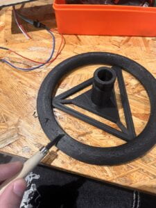
Wheel TinkerCad: https://www.thingiverse.com/thing:1066846
Lever TinkerCad: https://www.thingiverse.com/thing:4550772