Ideas and Design
For this project, Rainee and I decided to continue the concepts and designs in our first project, to create biomimetic fish body. As this project is about exploring mechanism that could create movements for the wearable, we think about elements that would move for fish and ocean creatures. One of the most intuitive element is the fishing scales, which would react to not only its own movements but also the surroundings.
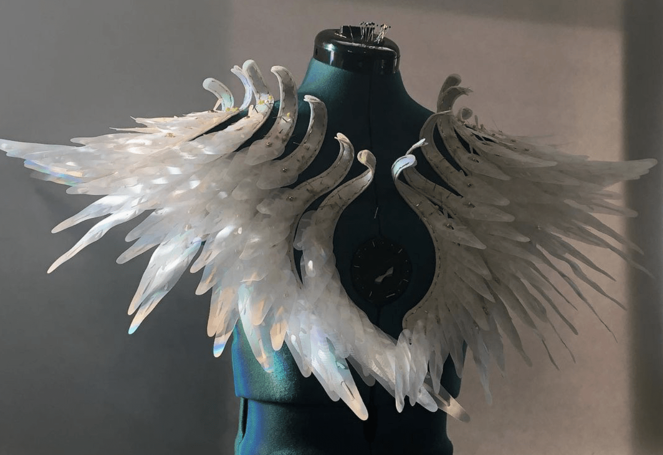
We get inspiration from work by Casey Curran, with the mechanism that would unfold pieces by pulling strings.
Regarding the interaction part, we decided to use distance sensors to mimic the scenario where other lives or items are approaching the ocean creature. When objects are dectected within a certain distance, the creature would show defensive movements, where the fishing scales would have rapid movements to either warn the approaching creature or to run away quickly.
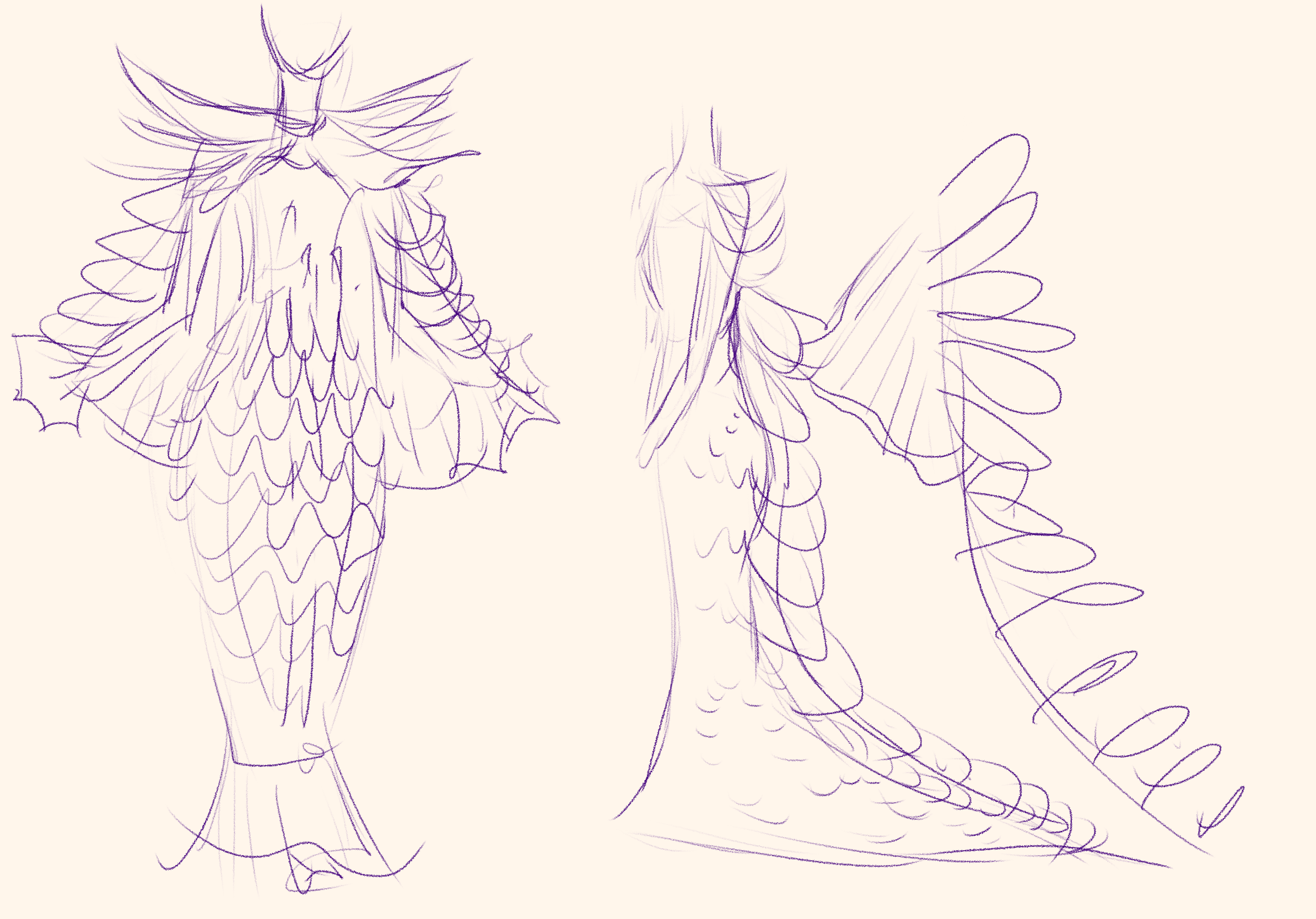
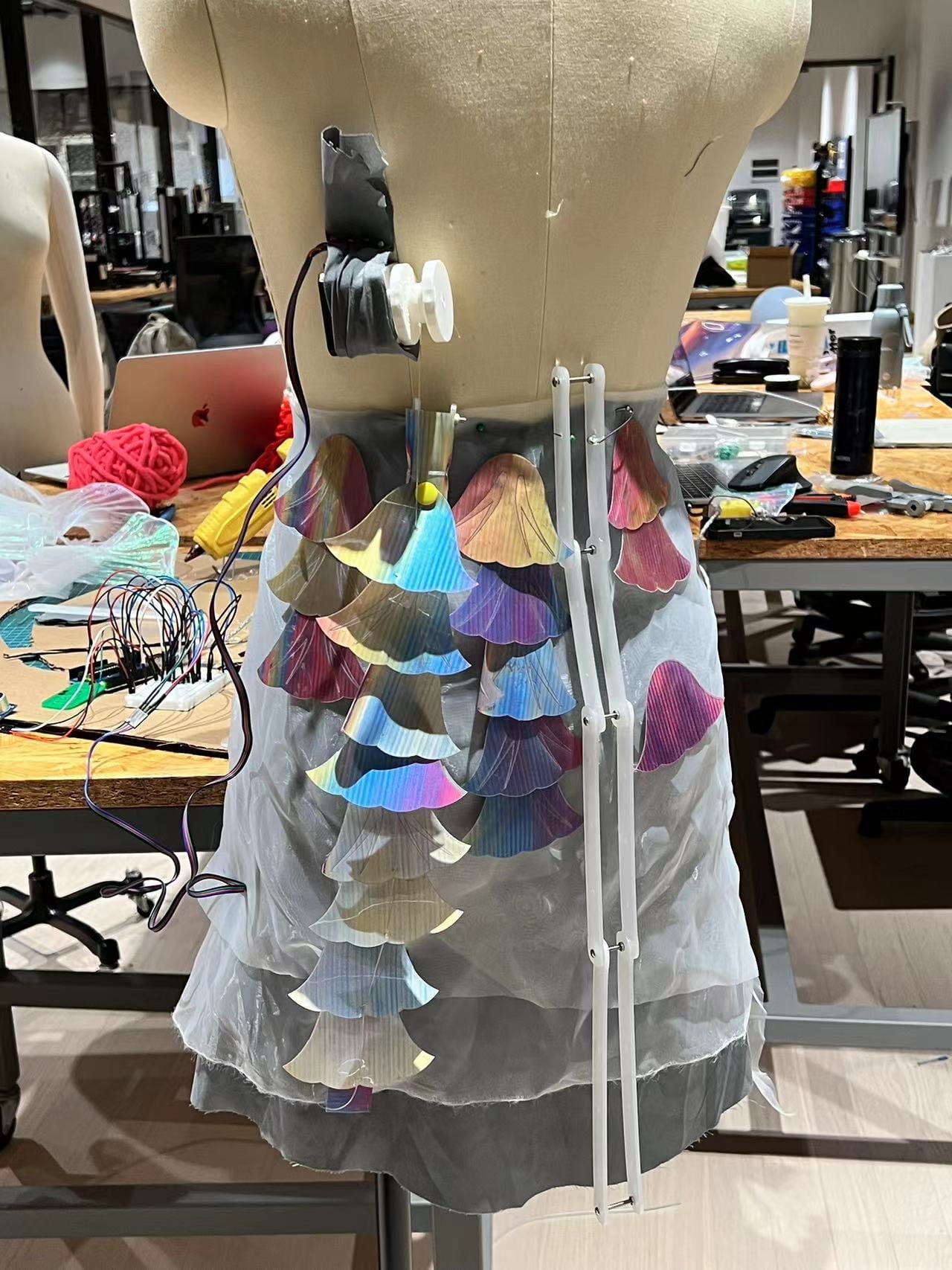
Therefore, the major part of this project is to experiment with mechanism and and materials to mimic the fishing scales movements. We plan to place such scales on the lower half of the body. Instead of making every scales move, we decided to separate scales into two parts, the positively moving ones, and the negatively moving ones. We design to have strings on one fraction of the scales that would move when pulling the strings. Other scales are not connected to the string and motor, but would be overlapped with those positively moving ones, so that when those scales unfold, these negatively moving scales would also move, not due to the string and motor, but due to the movements of surrounding scales. In this way, we could greatly reduced the number of motors used, and having different movements for scales in different positions, making the whole movement more dynamic.
One other movement was to have the dress itself moving, with the “bones” of the structure lifting up and down, the whole dress would move upwards and downwards. Such behavior resembles the movement of jellyfish and other soft tissue creatures.
(See detailed designs and concepts in Rainee’s Post)
Mechanism & Materials
Fishing Scales
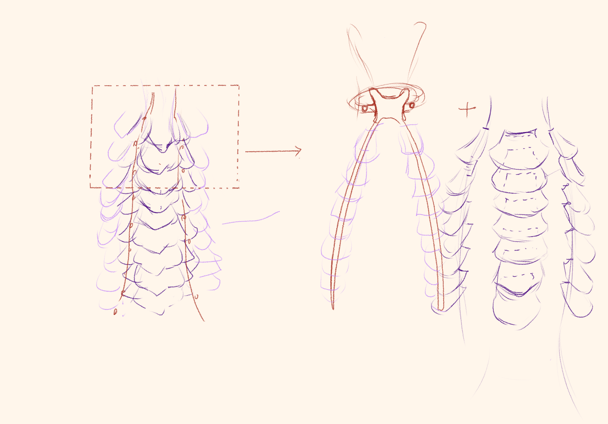
Continued upon assignment 7, we continued to explore both the mechanism and materials for the fishing scales. We decided to use the mechanism of jointing every scale to one string, so that when the string is pulled, every scale would move at the same time to mimic the movements of scales unfolding. Several major tasks to solve are 1. explore the joining position of fishing scales to the string, 2. the attachment of scales to the base clothes, 3. the material of fishing scales, and 4. the motors used for the movements.
In previous prototypes, we tried to make holes both at the bottom and at the top edge of the scales. When string holes were at bottom, pulling a shorter distance could lift the scale up, but at the cost of requiring more strength. Having holes at the top edge is the opposite situation, when longer string needs to be pulled, with relatively less strength. We first tried all holes at bottom or at top, finding that neither strategy worked very well. They all faced the problem that the first few scales would unfold greatly, but the scales at bottom would have much less movements.
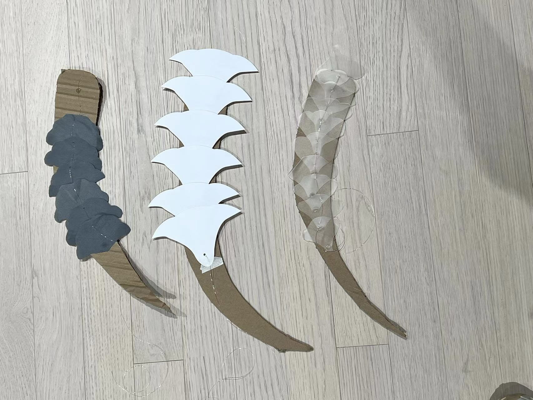
After finishing the kinetic prototype, I explored again with the position of holes. This time, I first made all the holes at bottom and then tried to make them all at the very edge of the scales. I found out the main reason for the latter scales to have little movement was the movement of the base. If all strings are secured and the base move no more after fixing everything, the scales could move just fine. However, once the base moved a little bit, so that the string between two or more scales could become either too tight or too loose. In this situation, the scales would have movements to different extents.
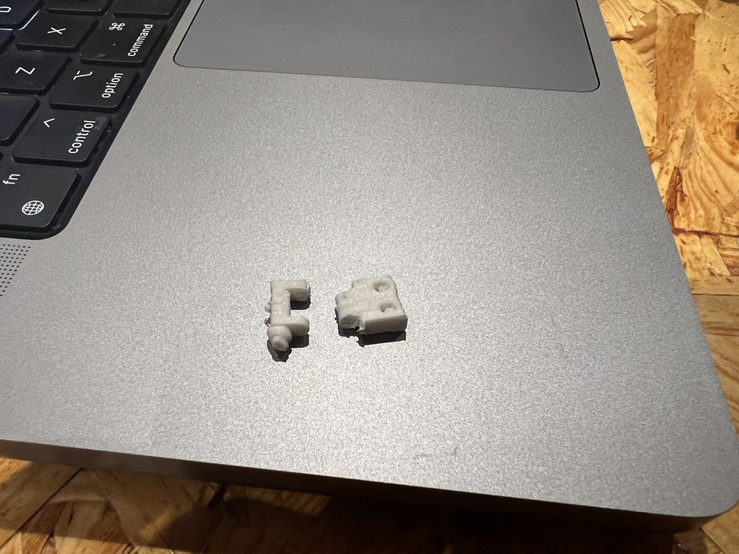
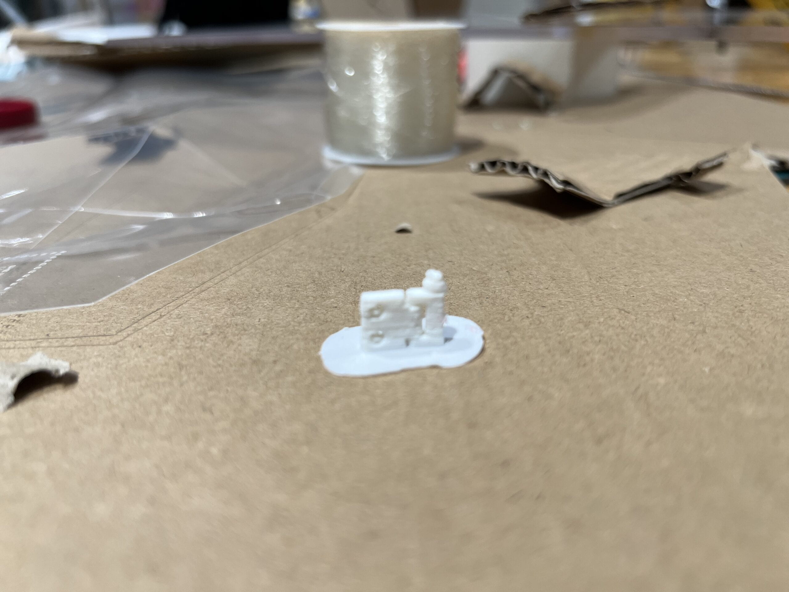
As for the attachments to the base clothes, we designed several different ways. Initially we had the idea of using acrylic as scales, so the scales could not be simply glued or sewed to the base, and we designed to use hinge joints to connect the acrylic scale with the base. We used 3D printing to build the hinge joints. The first one printed was too small that the inner structure was not clearly printed, and it easily broke from the middle. Then we tried a bigger second one, however it also did not function as desired. We hope the hinge joint to have a hollow gap so that it could rotate freely, however with the given size, 3D printer could not accurately print the structure. Along with other reasons such as the long printing time and probabilities of failing, we decided to not continue with 3D printing. Therefore, we gave up the idea of using hard materials for scales, and turned to soft materials such as paper and TPU.
When using soft materials, we no longer need to use hinge joints. Professor Marcela provided us with buttons that could be easily installed to join the scale and the base clothes together. And we used these buttons for this project. One minor problem is that such buttons are too large, as the fishing scales are rather small. The buttons do not look so good on the scales and would prevent us from making holes at the very bottom of the scales. Therefore, we might continue to try different joints for our final project.
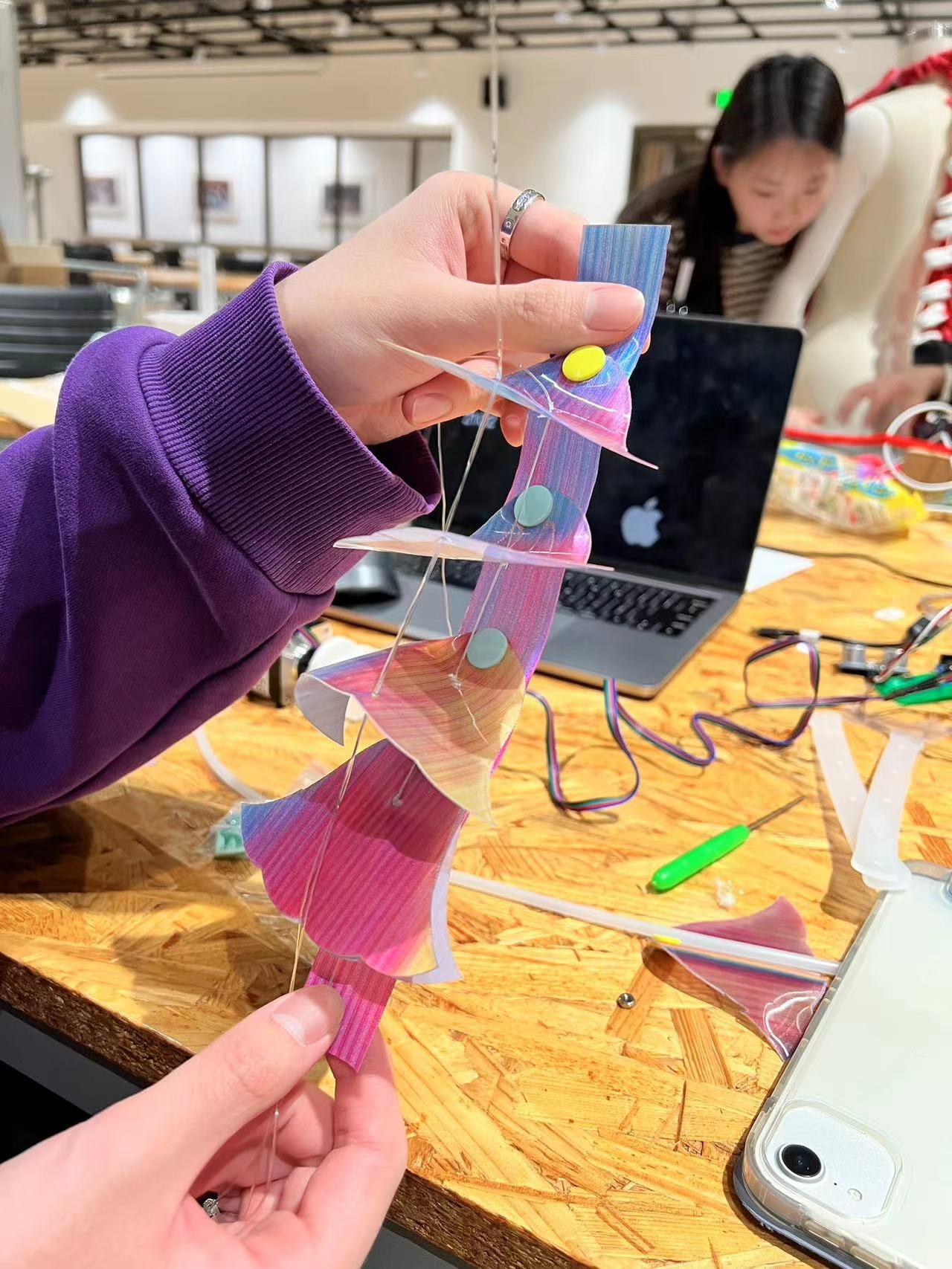
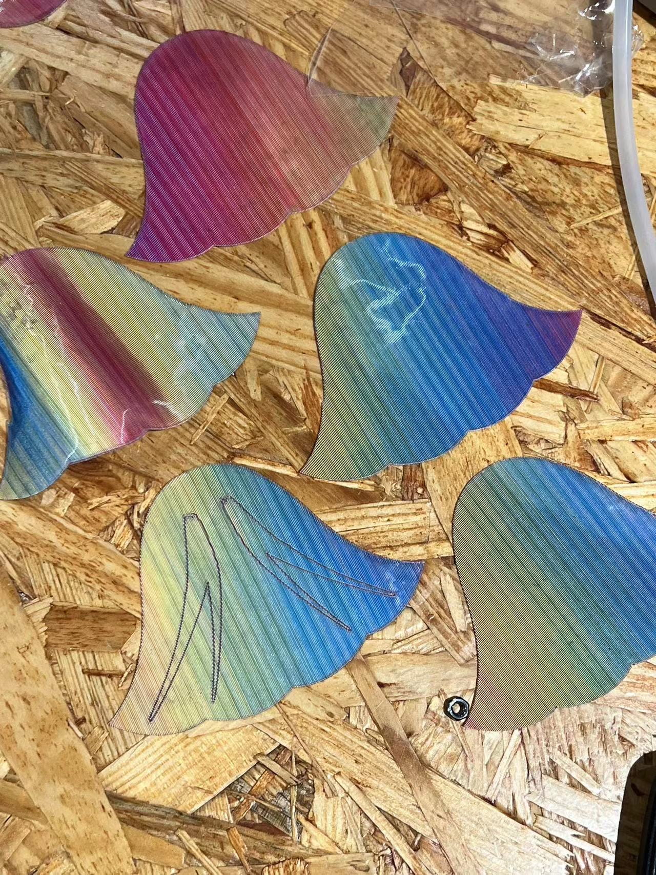
As mentioned above, we discarded the idea of using hard scales and turned to soft ones. The major problem was that most materials are too soft, so that when they were lifted up, the scales might not be able to lift other negatively moving scales. We tried to use TPU, but it was too soft to hold other scales. Thanks again to Professor Marcela, she gave us one kind of soft fabric that is strong enough to hold other scales, and at the same time very beautiful, which greatly resembles the real fishing scales.

Regarding the choice of motors, as documented in the previous blog, we tested the DIY actuator, which turned out to be not powerful enough. I then left with three choices, servo motor, DC motor, and stepper motor. I designed the way to use motors just like kites and fishing rods, where the motor rotates would prolong or shorten the wire. In this sense, I decided to not use the servo motor mainly because the servo motor is too small and could only rotate for 180 degrees. Therefore, it could not prolong enough length of wire to pull the scales up. I then quickly tried a small DC motor. The main reason for me to not use it was that I did not figure out the way to change its rotate speed through codes, but only through controlling the power adaptor. I would probably give DC motors another try in the future.
I used the stepper motor at last, because I could accurately control the angles of rotation and its speed, so that I could pull the string to the exact position I wanted. However, the downside was that the stepper motor is too heavy, it might be a problem if we want to use multiply motors in our final work.
Bone Structures
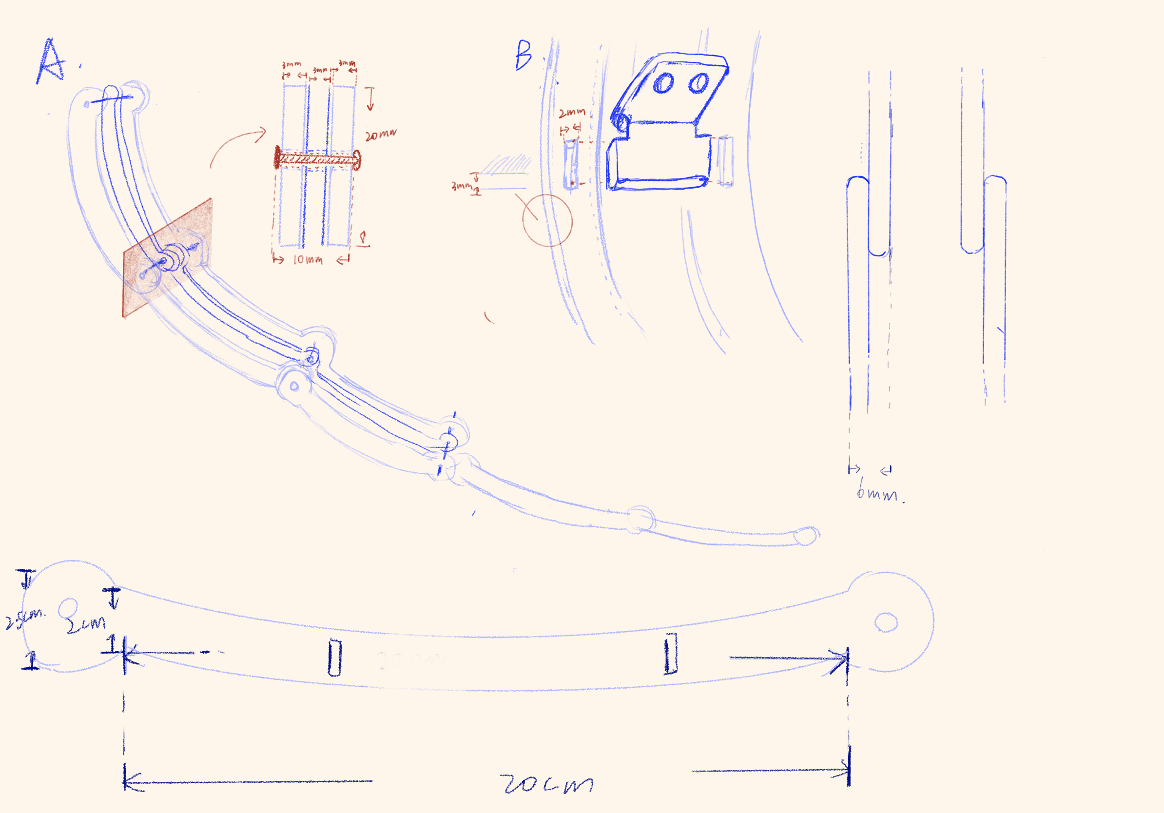
We designed the bon structure to also be controlled by strings, not using motors but using user’s own arms. I wanted to connect the bottom end of the structure to the user’s wrist. With the top end of the structure fixed on the dress, once the user lift its arm, the dress would also be lifted.
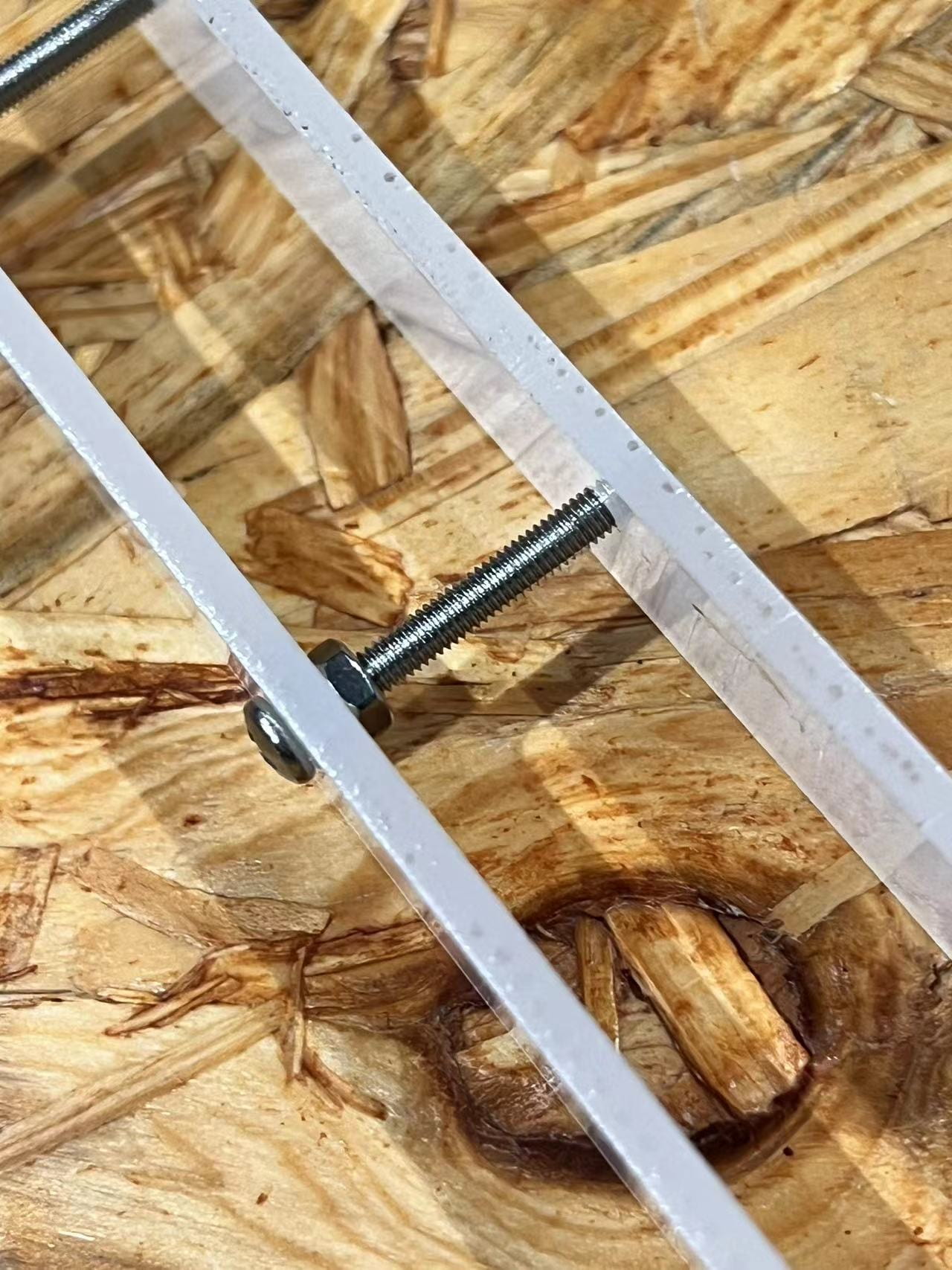
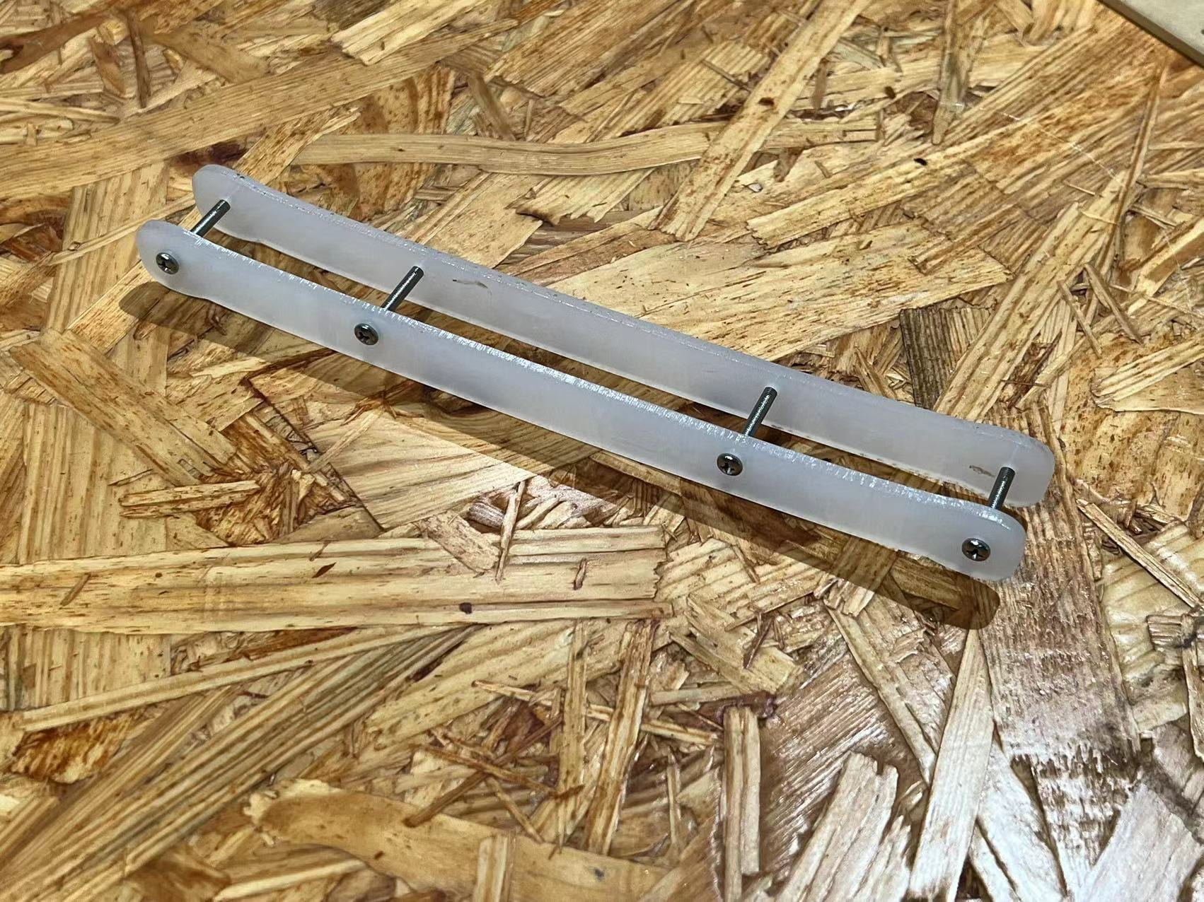
To achieve this effect, Rainee and I designed the joint that could rotate, and utilized laser cut to create the structure. We cut acrylic boards into several strips with different length. By jointing these acrylic strips together, we obtained this structure that is strong enough to hold clothes and able to bend. After cutting these boards out, we found that we could actually narrow these strips further and shorten the length of each one, so that the angles of bending could increase.
Since this mechanism does not involve motors and is much intuitive than the scales one, we did not meet much trouble in creating the prototypes.
Circuit & Code
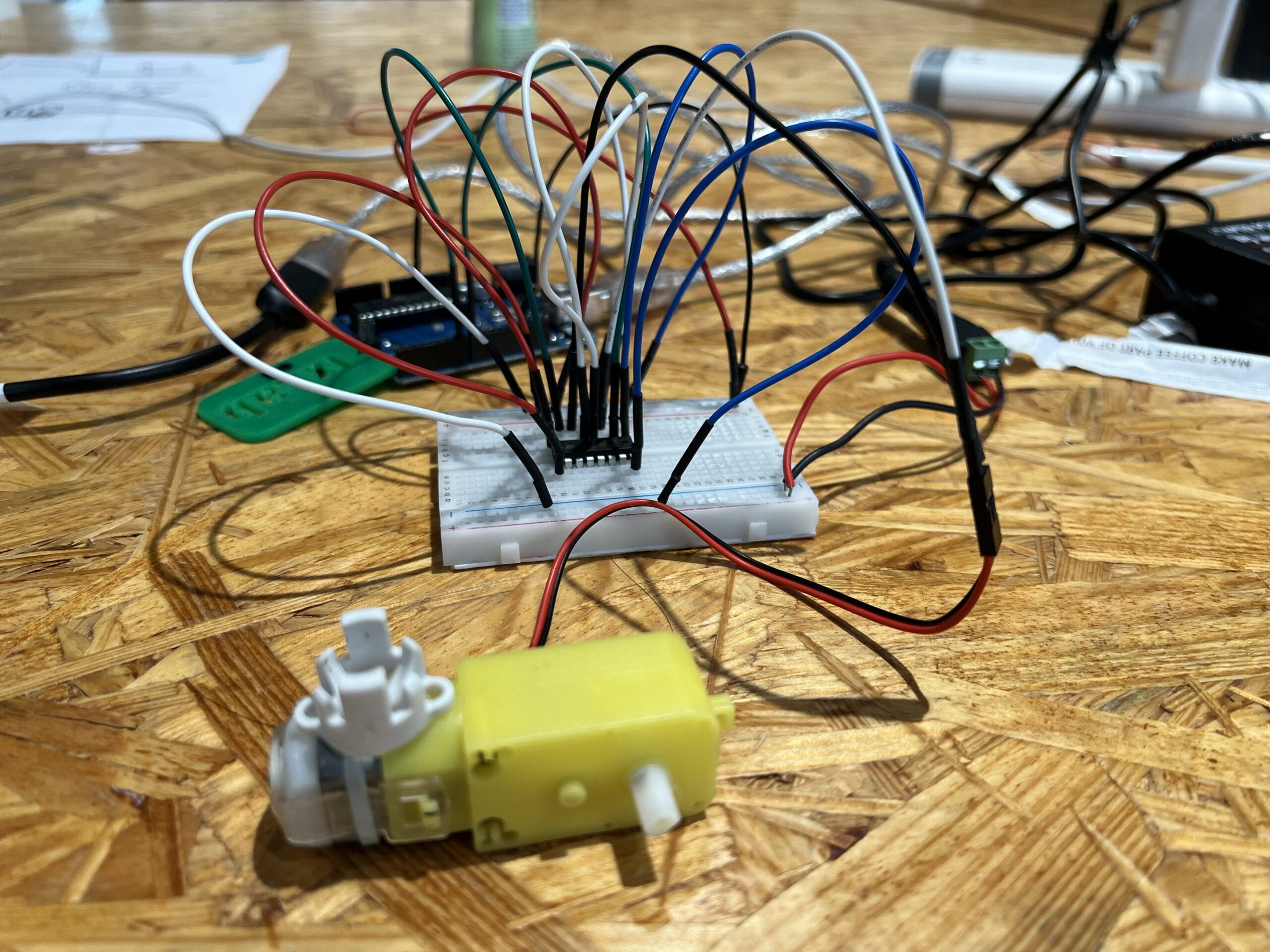
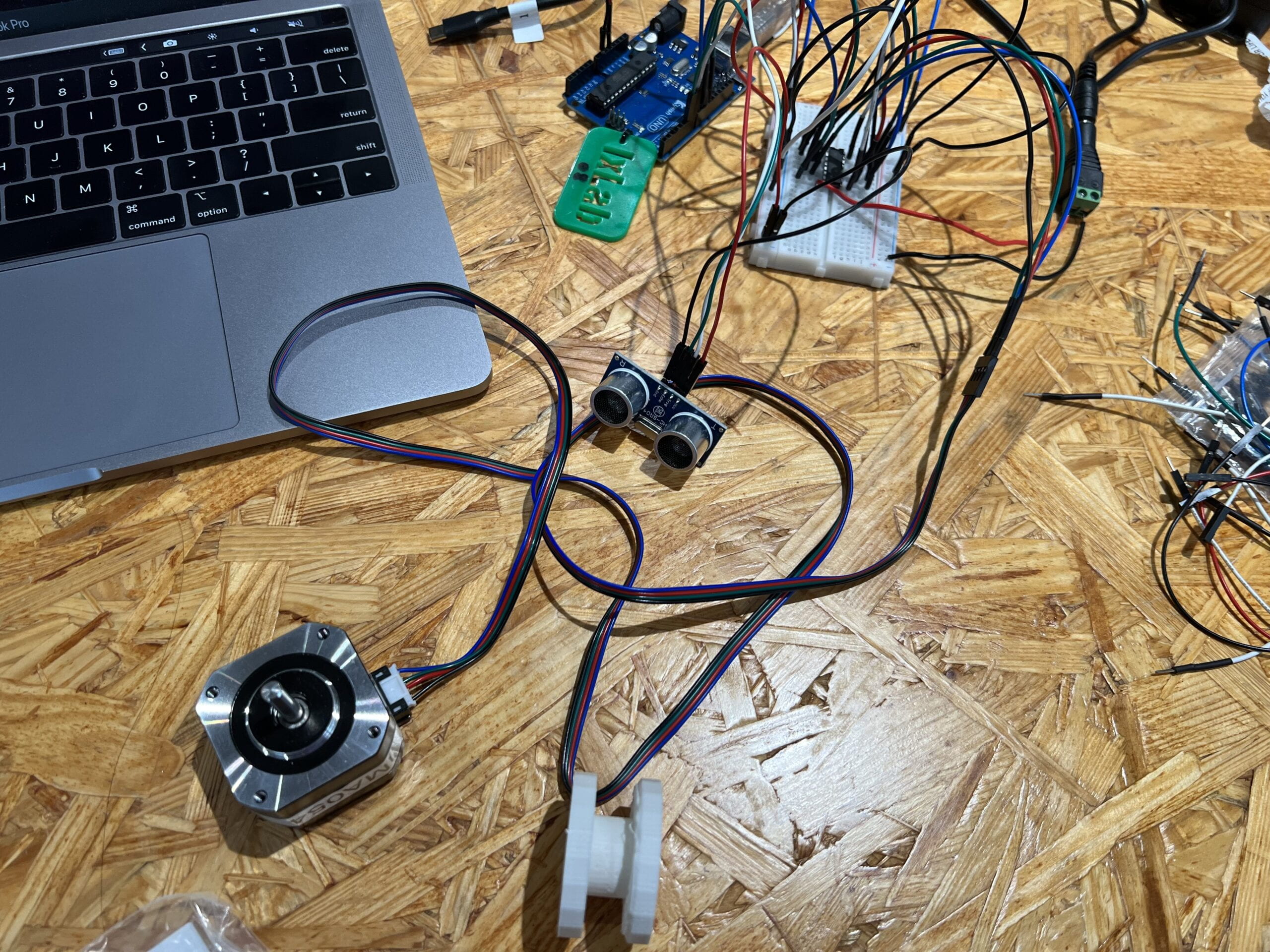
The circuits and codes are used to control the stepper motor and the distance sensor on the scales mechanism. The overall building process was not so difficult.
Just as mentioned before, we decided to use the stepper motor for this prototype. The circuit is relatively complex, but not difficult to build. One H bridge is used to control the stepper motor, just like the circuits in previous weeks.
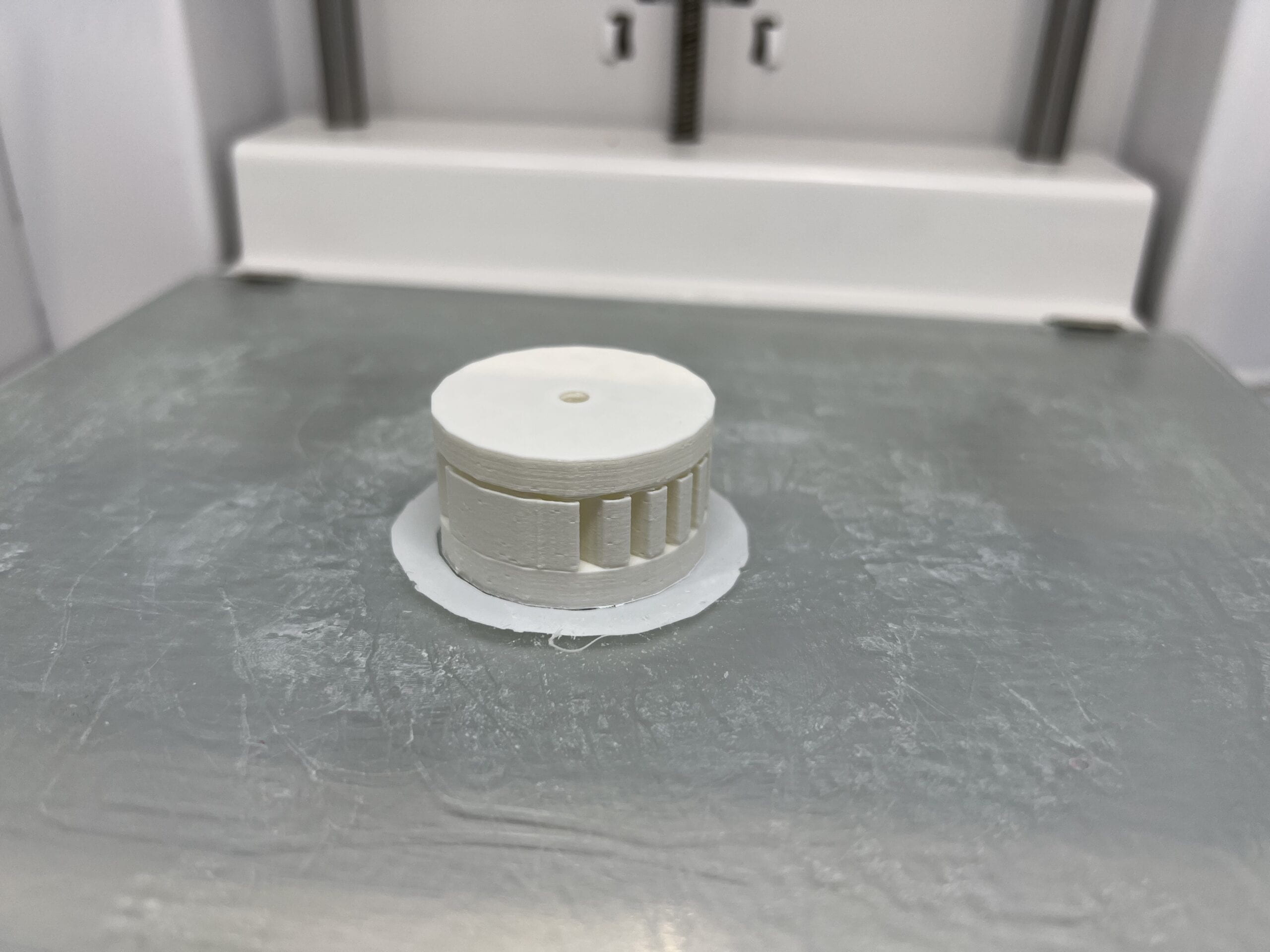
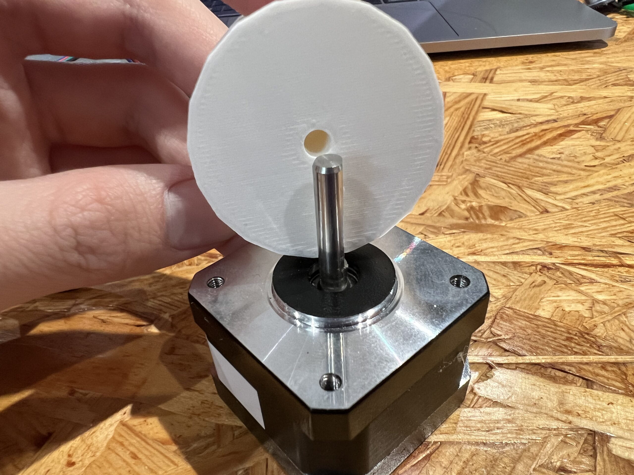
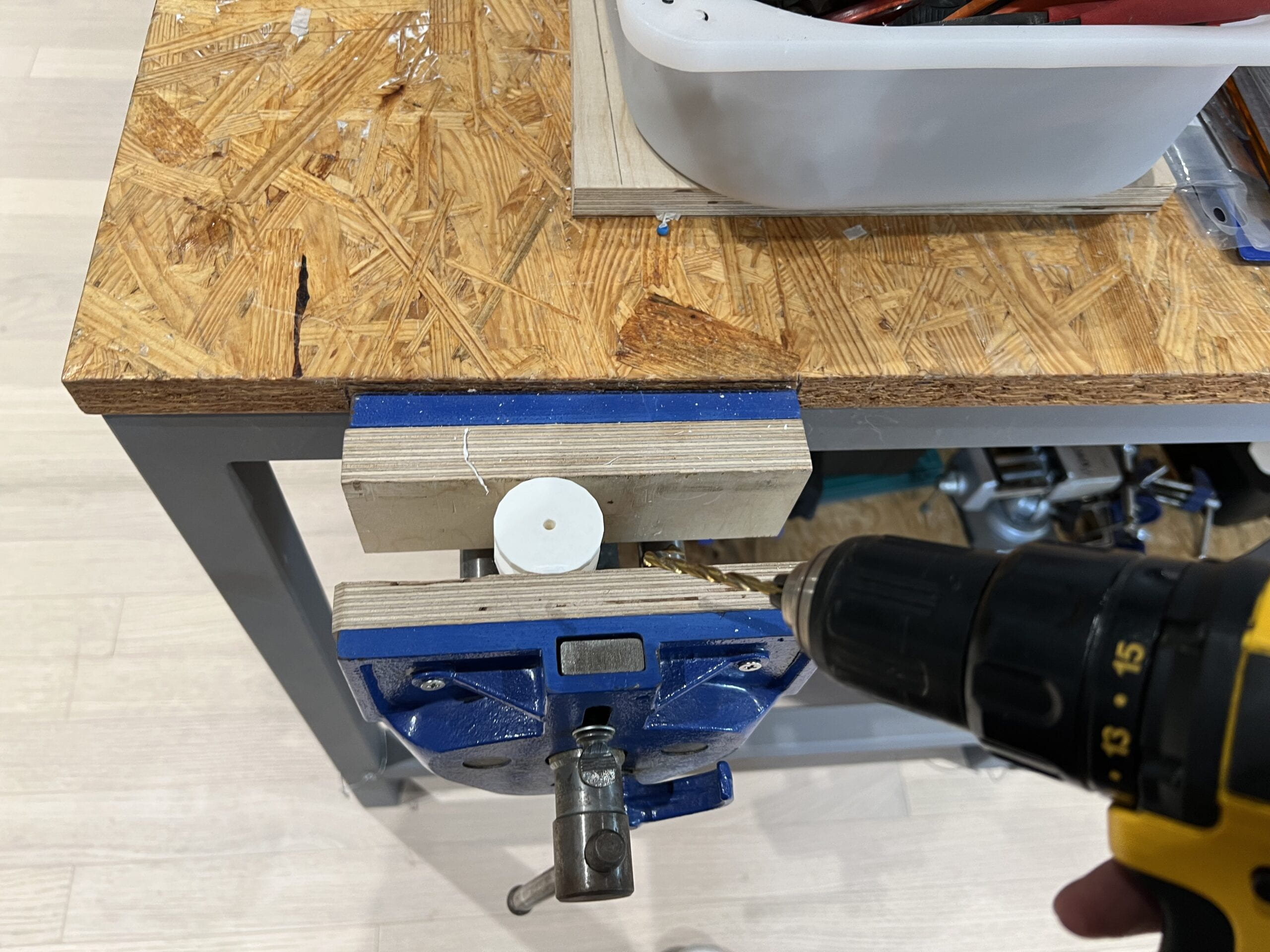
In order to have the stepper motor works like fishing rods, I need one wheel that has larger radius than the stepper motor itself, so that less rounds of rotation is required to pull up strings for the same distance. Thanks to Johnny who provided me with the digital model of wheel, I 3D printed the wheel that can be inserted into the motor. It turned out that the hole in the middle of the wheel was not big enough for motors, so I used a hand drill to enlarge the hole a little bit. The 3D printed wheel worked very well to hold the wires.
After measuring the distance required to pull the wire, I changed the codes so that the stepper motor would rotate the exact angles to pull up and release the wires, so that the scales would move up and down.
As for the distance sensor, I used one ultrasonic distance sensor that could detect the distance of any object facing it. I used the sample code to control the distance sensor and calculate the distance in centimeters.
int detect_distance() {
  digitalWrite(trigPin, LOW);
  delayMicroseconds(2);
  digitalWrite(trigPin, HIGH);
  delayMicroseconds(10);
  digitalWrite(trigPin, LOW);
  duration = pulseIn(echoPin, HIGH);

  distance = duration * 0.034 / 2;
  return distance;
}
The main difficulty in the codes part came when combining the sensor and the motor together. I planned to change the speed of motor when the distance changes. However, in the Arduino circuit, no distance would be detected when the motor is rotating, because the rotation command is in one line of code, and the software would not jump to the next line before the rotation is completed. Therefore, I could not detect the distance constantly and change the speed. I decided to have an average distance by taking ten distance sensor values in between every two circles of the motor movements. If the average distance is below a certain value, the motor would have higher rotation speed for the next circle.
void loop() {
  distance = average_distance();

  if (distance > 30){
    speeds = 30;}
  else {
    speeds = 60;}
  myStepper.setSpeed(speeds);
  myStepper.step(steps);
  myStepper.step(-steps);
}
The detailed codes are attached at the end of this post.
Further improvements
Generally speaking, our prototype met our expectations of exploring the material, circuits, and mechanisms. Some of the limitations and potential improvements are documented above. We would continue to explore the position of holes on the scale and try to find an optimal position so that each scale would move roughly the same distance. We would also try new attachments for securing the scales onto the base clothes, potentially smaller buttons or maybe sewing. As for the motors, I will try again the DC motors, especially the gear DC motors suggested by Professor Marcela, I will learn to control the speed and rotation of DC motors using only codes, but not the power adaptor.
For the circuit, I expect it to be even complex as we would probably use multiple motors, and such circuit needs to be wearable to some extent. I plan to try soft circuit with conductive wires, and see if that could help building the circuit neat and tide, while in a secure way that would not be easily damaged.
For the codes, the biggest limitation lies in the interaction between sensors and motors. Just as mentioned above, the codes right now could not read distance constantly, and such problem could not be easily solved, due to the nature of motors. I currently have to potential solutions, which I plan to try them out.
The first is to cut the rotation process into more periods. For now, the clockwise rotation and counter clockwise rotation are single movements. If I cut the rotation into ten pieces, then I am able to have the sensor return values in between each of these ten rotations, then I could have more distance values within the rotation process, and change the speed correspondingly. The downside of this approach is that the rotation process might look not continuous, as I have to stop and restart rotation many times, with the distance sensor working.
The second approach is to have two Arduino boards, one constantly reading distance values, and the other controlling the motor. In this way, I could have continuous distance inputs, and easier to calculate average distance. However, I still need to figure out how to change the motor speed when it is working. And the circuits would also be much complex if using two Arduino boards.
#include <Stepper.h>
const int stepsPerRevolution = 50;
int steps = 115;
int speeds= 40;
// initialize the stepper library on pins 8 through 11:
Stepper myStepper(stepsPerRevolution, 8, 9, 10, 11);

const int trigPin = 7;
const int echoPin = 6;
long duration;
int distance;
int sum_distance;

void setup() {
  pinMode(trigPin, OUTPUT); // Sets the trigPin as an Output
  pinMode(echoPin, INPUT); // Sets the echoPin as an Input
  // set the speed at 60 rpm:
  myStepper.setSpeed(speeds);

  Serial.begin(9600);
}

void loop() {
  distance = average_distance();
  Serial.println(distance);

  if (distance > 30){
    speeds = 30;
  }
  else {
    speeds = 60;
  }
  myStepper.setSpeed(speeds);
  myStepper.step(steps);
  myStepper.step(-steps);
}

int detect_distance() {
  digitalWrite(trigPin, LOW);
  delayMicroseconds(2);
  // Sets the trigPin on HIGH state for 10 micro seconds
  digitalWrite(trigPin, HIGH);
  delayMicroseconds(10);
  digitalWrite(trigPin, LOW);
  // Reads the echoPin, returns the sound wave travel time in microseconds
  duration = pulseIn(echoPin, HIGH);
  // Calculating the distance
  distance = duration * 0.034 / 2;
  return distance;
}

int average_distance () {
  sum_distance = 0;

   for (int i=0; i<10; i++) {
      sum_distance = sum_distance + detect_distance();
   }
   return (sum_distance)/10;
}