In-class Recitation
For more detailed documentation and code files, see the collaborative notion page.
Teamed with Mia, Freya, and Annika, we made a wireless circuit, taking advantages of the X-Bees. Besides the complex instruction and the fancy materials, the overall circuit was easier than I thought. We built a wireless circuit with two ends, one sending signals generated from one photoresistor, the other receiving the value and showing the transformed data in Processing.
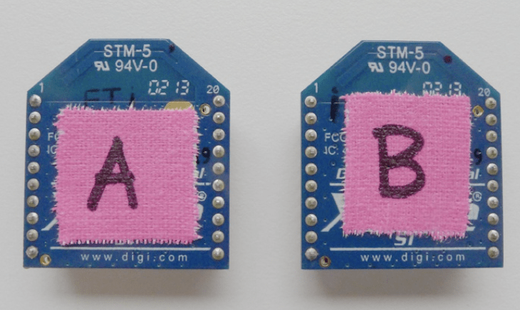
Annika and I mainly focused on the first X-Bee (and lilypad A), the one sending values from the brightness sensor. Before building the circuit, our first step was to match the two X-Bees together. Using the application XCTU, we matched the X-Bees with the same pin code and assigned the sending and receiving duties to them.
The next step was to connect the X-Bee to a normal Arduino circuit. We first built an simple Ardunio circuit with the photoresistor, such that the circuit takes an input from the brightness sensor, and the value varies when light is shed on the sensor. Then, we tried to add the X-Bee to the lilypad, so that the lilypad would output the brightness sensor’s value to the X-Bee.
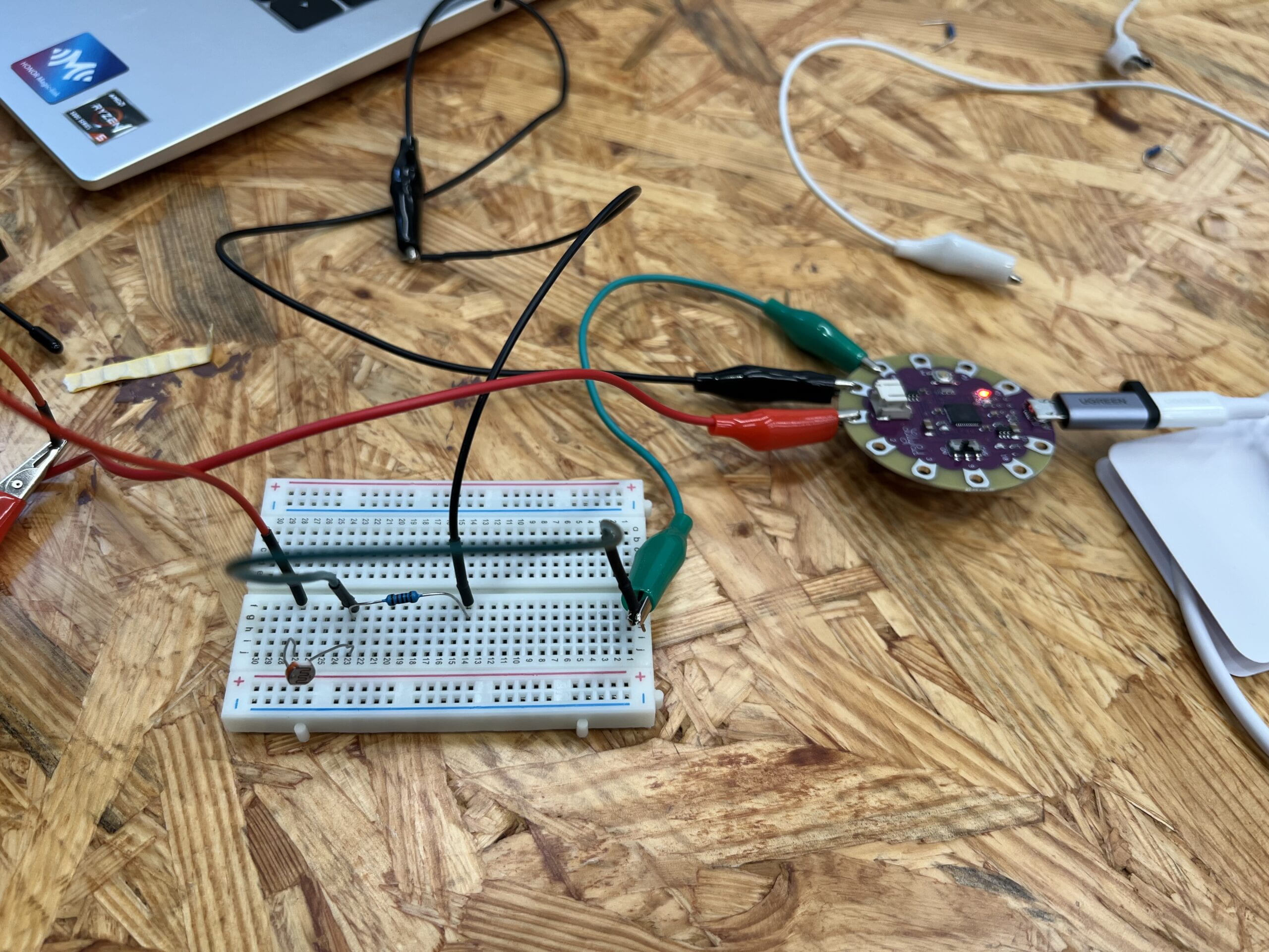
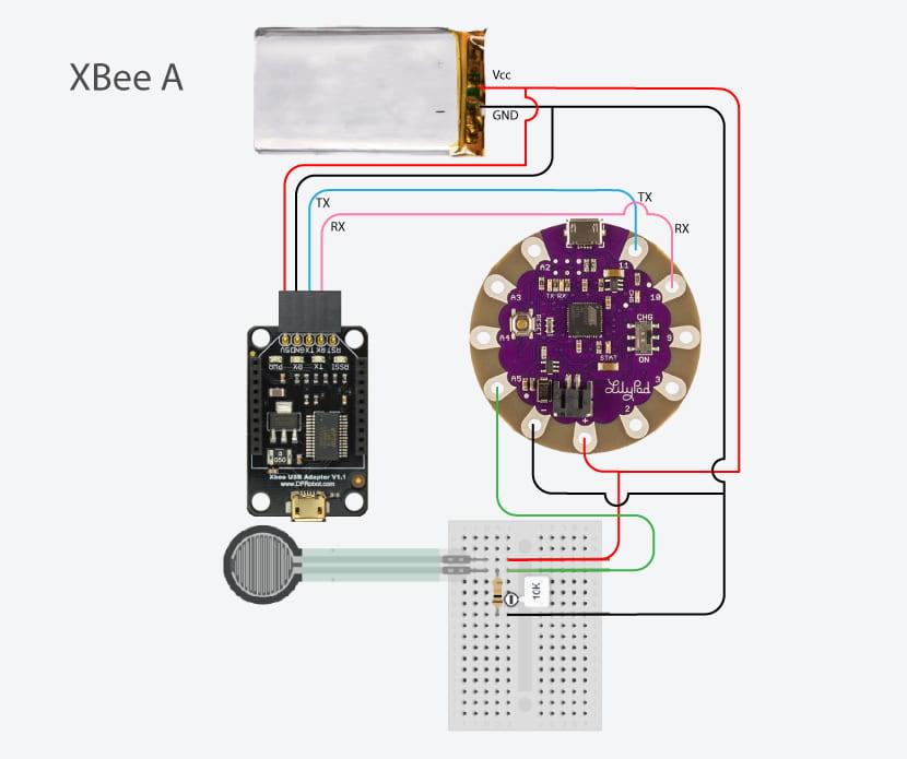
We met two major problems in this step, the first one is about connecting the circuit with the battery. The given circuit was to connect both the X-Bee and the lilypad to the 5V battery. However, we only have our laptops to battery them. After trying to use two laptops to charge each of them, we then figured out to just simply connect the lilypad to laptop, then use the 5V port on the lilypad to charge X-Bee. Our second problem was to test if the circuit was fully functioning. We tested before that the lilypad and the photoresistor were both working, but we were not sure if X-Bee is receiving the value from our circuit and successfully sending that value to the paired X-Bee. We tried to follow the instruction of changing the input and output pins and monitor the X-Bee values, but we failed to find that exact window monitor in the XCTU application.
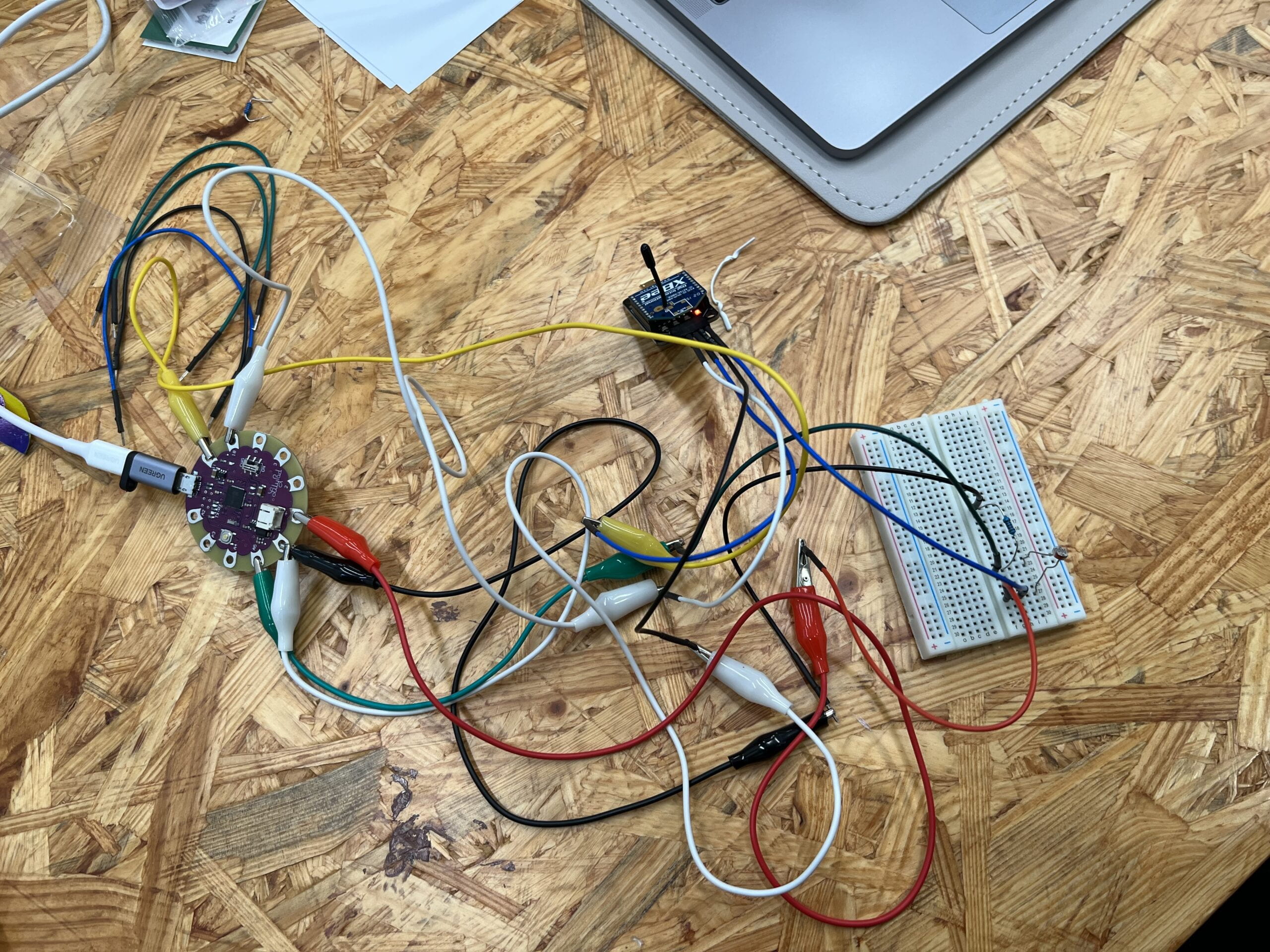
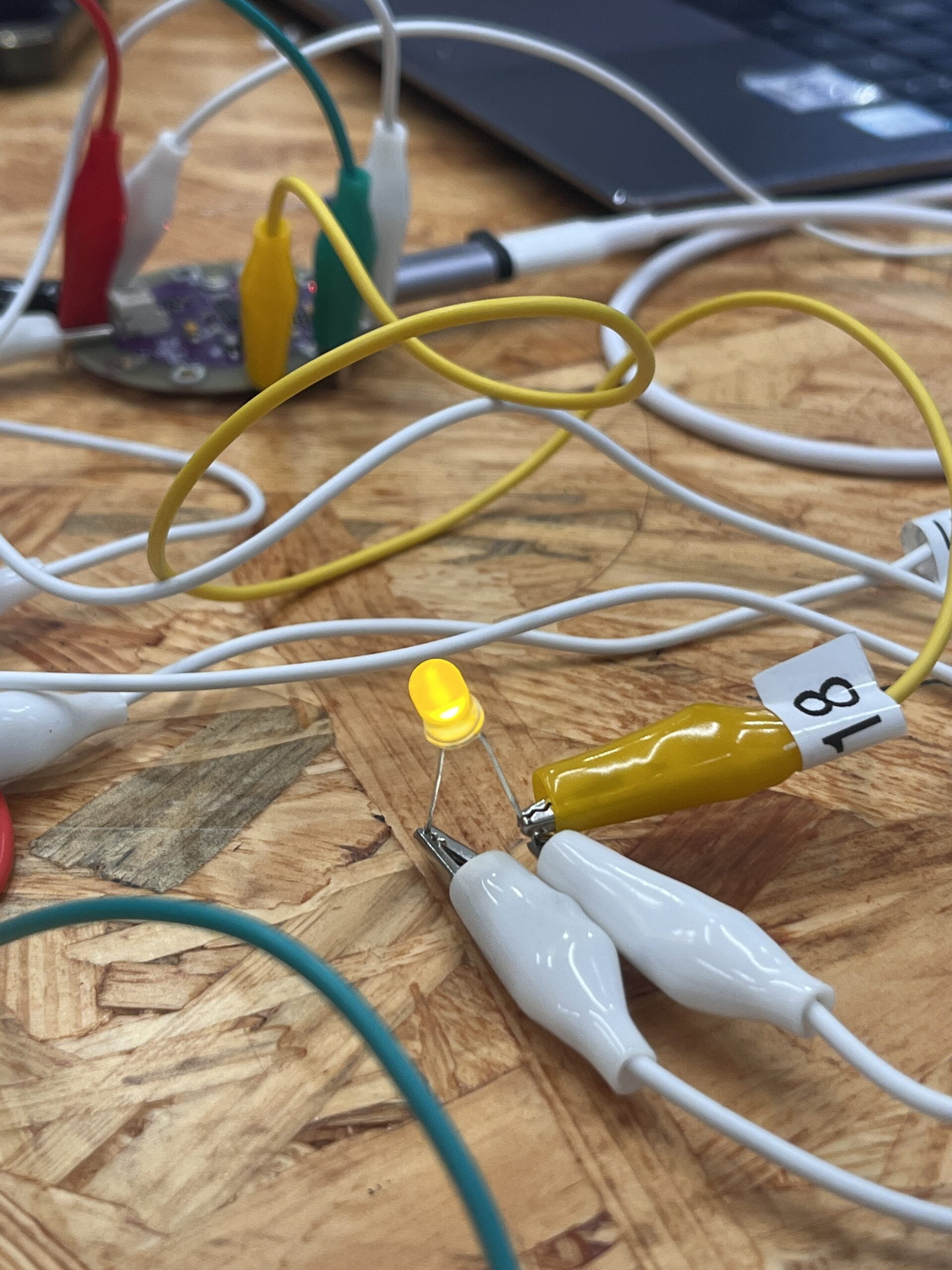
Although we did not succeeded in testing our part of the circuit, we saw the whole circuit working smoothly once Mia and Freya finished their part of the second X-Bee. The photoresistor sensor value was shown on their Arduino window monitor in real time. One minor problem we encountered at this stage was that in circuit X-Bee B, the received value was intended to control the brightness of one LED. However, though we succeeded in receiving the value, our LED never blinks or dims. Even after we finished the whole exercise (where the Processing was controlled by the photoresistor), the LED problem was unsolved. With help from the professor, we finally figured out that we accidentally gave to inputs and outputs to the LED, saying that we have one input controlled by the sensor, and one other input of constant 5V. Therefore, the LED was always reacting to the 5V input and had a constant brightness.
Our next step was to create a simple Processing animation so that the brightness sensor value could control the radius of a circle on the screen. The processing part was also not difficult, and we finished it pretty smoothly.
We then spent the rest time of the class exploring the neopixel stripe, one stripe that has around 50 to 60 LED on it. However, we did not really figured out the neopixel stripe FastLED library in Ardunio to control all LEDs at the same time. Therefore, we did not add the colorful stripe to our circuit at last.
After-class Questions
How do you imagine you could use what you learned today for a wearable?
What I learned today is basically wireless circuits, where different parts of the circuit does not need to be physically connected through wires. So inputs (sensors) and outputs (LEDs) can be at different locations, and even multiple inputs or outputs can also be at different places. Such idea efficiently widen the potential for any circuits on wearable. Where the circuit is no longer fixed at one position, this creates millions of new potentials.
Some of the simple implication I could think of are that inputs and outputs can be at different locations of ones body, maybe the movement of head could control lights around your ankles. Another is to have wearables react to the environment, for example the input is controlled by some equipments away from the user, and the wearable could receive this long-distance signal and have reactions. One more exciting usage is that two wearables could interact with each other, maybe two people wearing these pair of wearables, and the movement of one people could have interactions on the wearable of the other.