Interactive Fashion | Final Project

Betta

—- by Alan Guo, Rainee Wang, Yasmin Pang

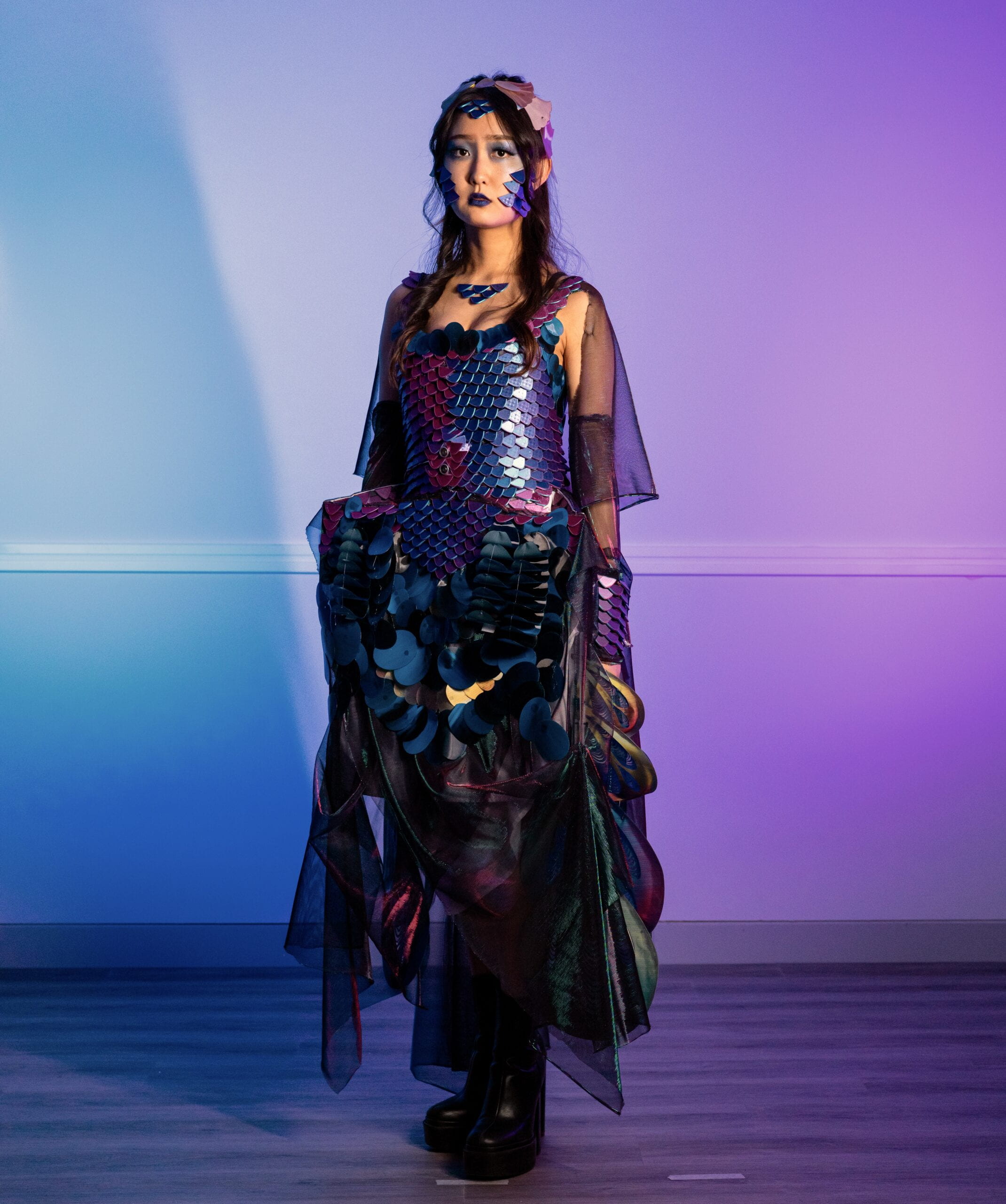
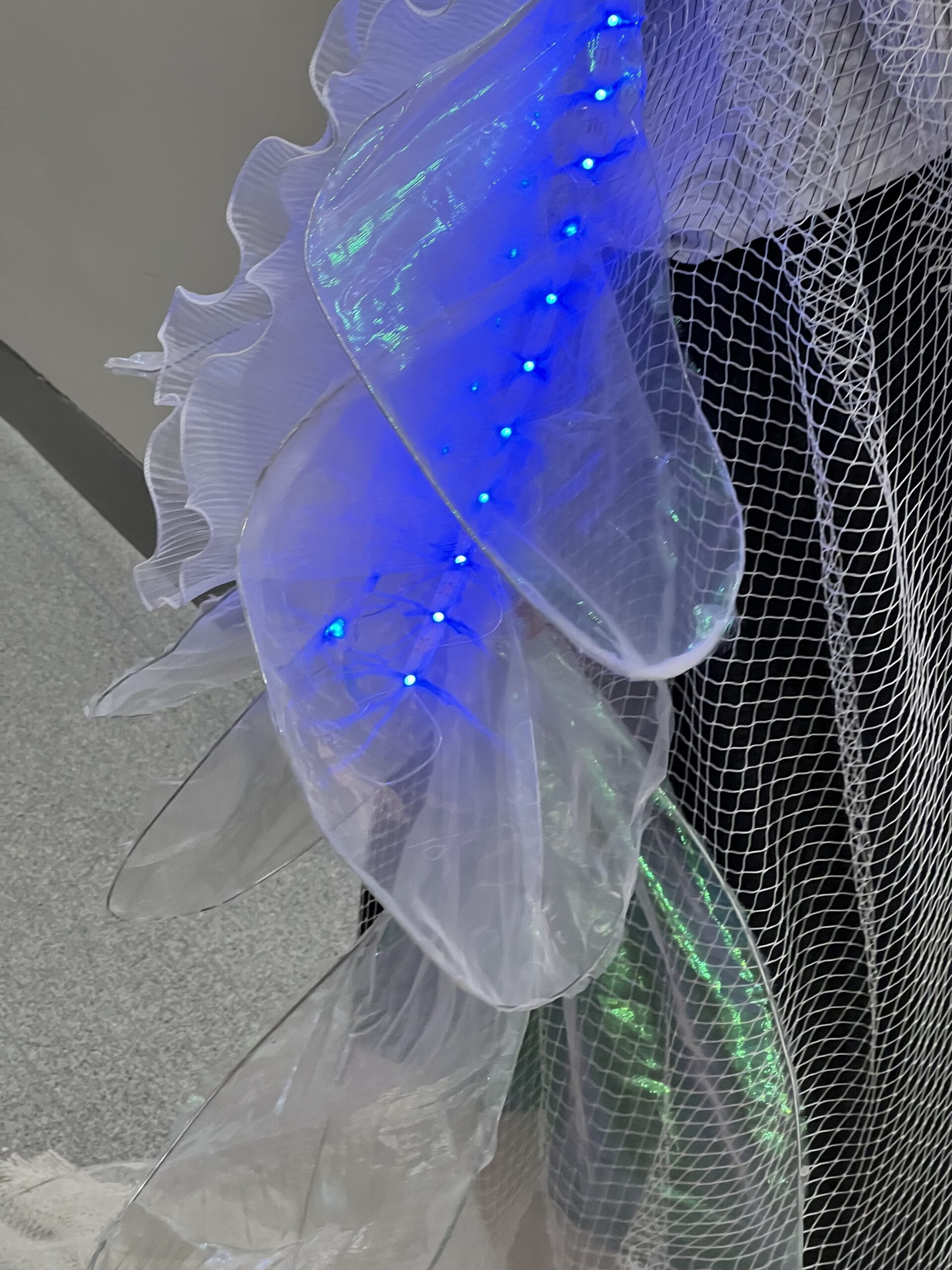
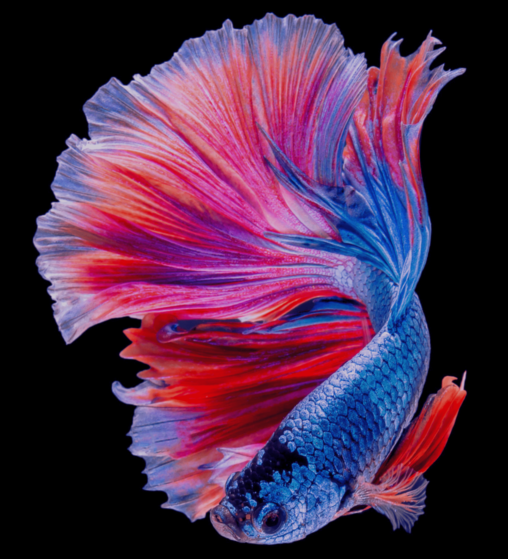
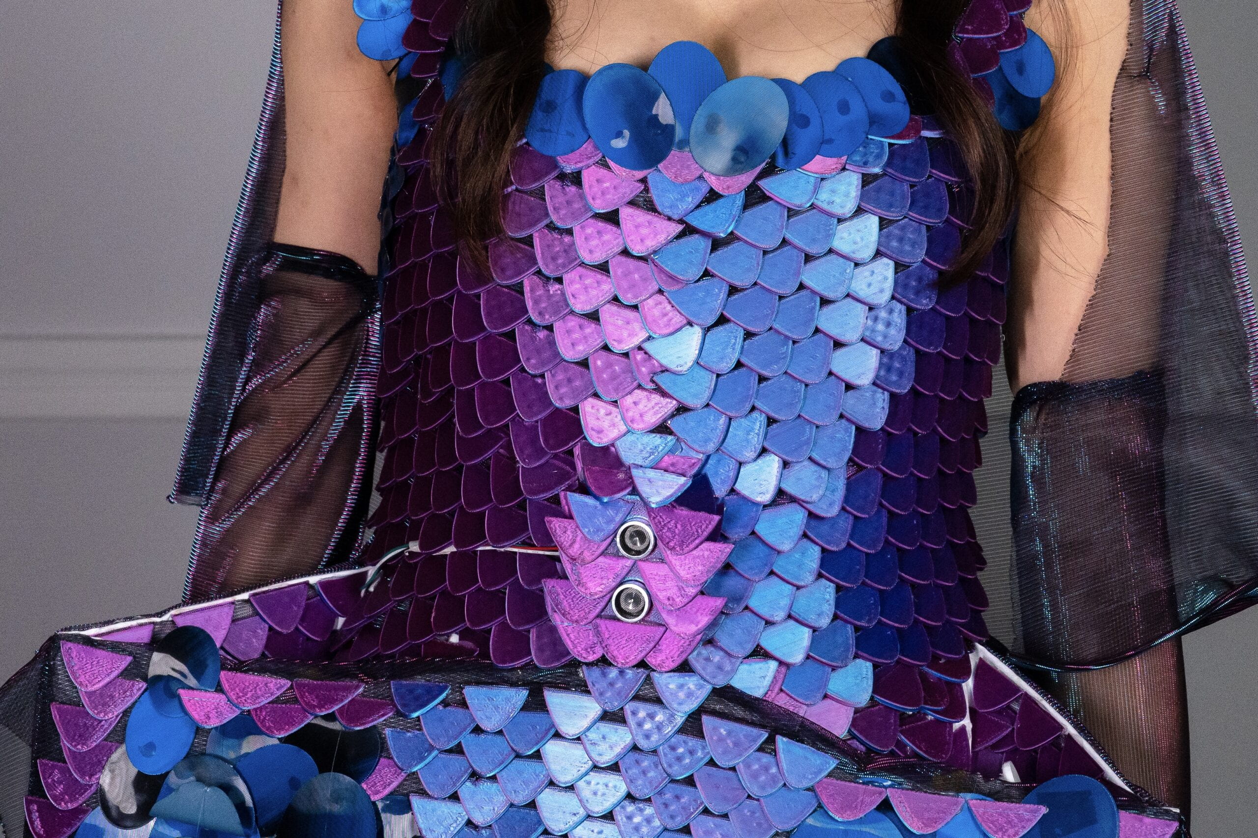
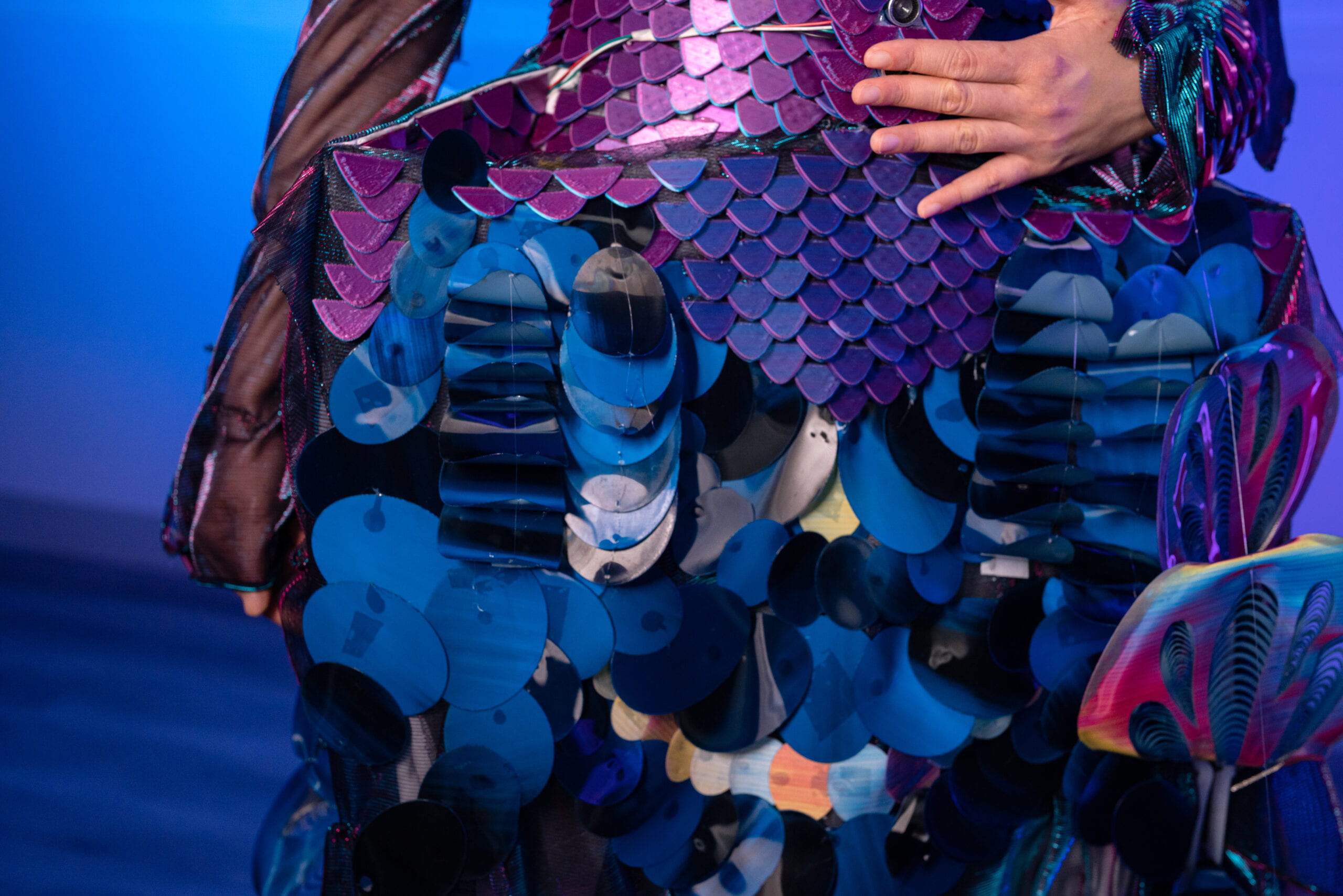
Betta is an interactive dress centered on the biomimicry of a fish-human hybrid. Created by Alan Guo, Rainee Wang, and Yasmin Pang, this dress mimics the appearance and habits of the betta (Siamese fighting fish), which reacts explicitly and violently to external threats when approached. When detecting the approach of objects, the dress scales will swing up and down to warn the intruder. In this way, Betta creates a hybridization of fish and human.

For this project, I mainly focused on designing 3D models and mechanisms, making 3D printing and laser cuts, building wearable circuits and codes, and assembling the scales and mechanisms. Rainee and Yasmin focused on developing concepts and overall dress looks, designing scale shapes, patterns and mechanisms, and sewing every element onto the dress. The overall working process follows that we brainstorm and design the overall dress, after that I manufacture items and elements, then Rainee and Yasmin build up the dress with fabric and scales. We also meet and discuss when problems are faced.

The following sections describe the detailed making process, with a special focus on parts that I am in charge of. As for the other parts, please learn about them from Rainee’s and Yasmin’s blog posts.

Concept & Design

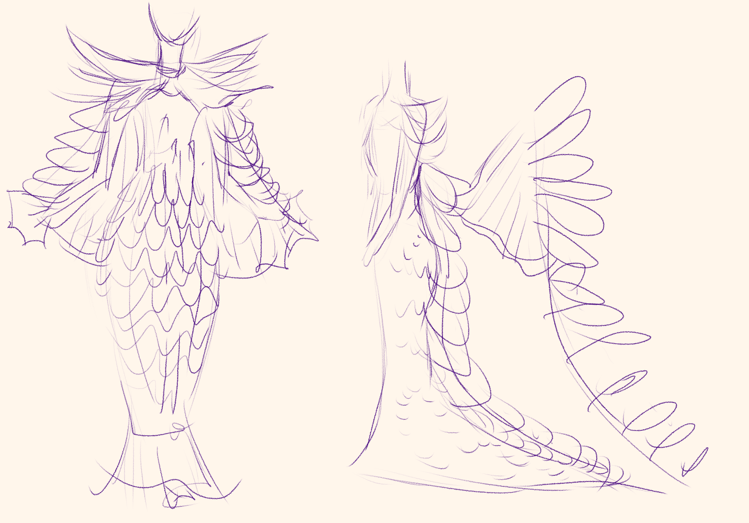
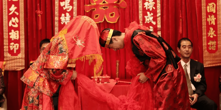
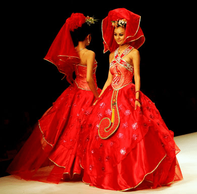
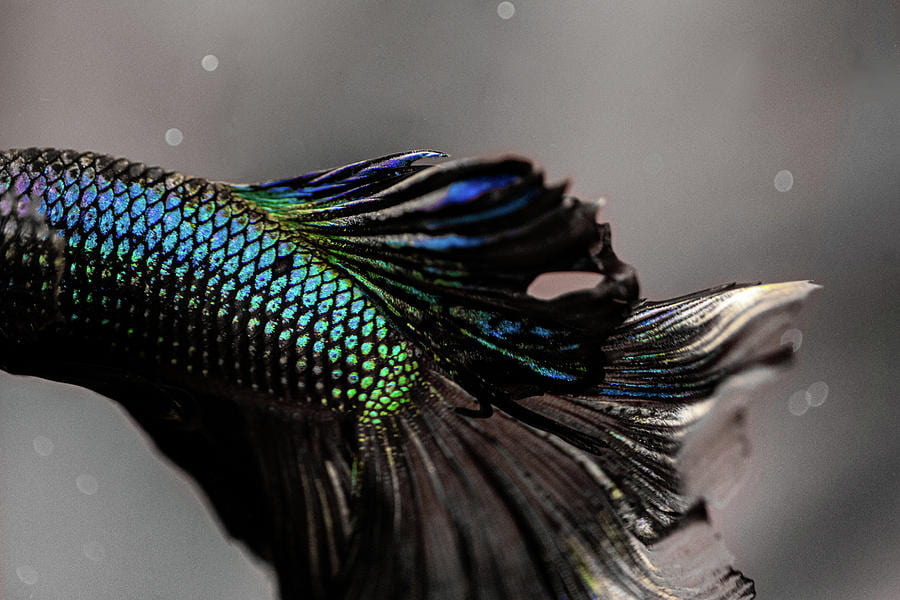
We generated our design from one kind of fish, betta (Siamese fighting fish), a normally dark blue and purple fish that will get into severe fight when other male fish come near to its own space. For detailed concepts, please see Rainee’s and Yasmin’s posts.

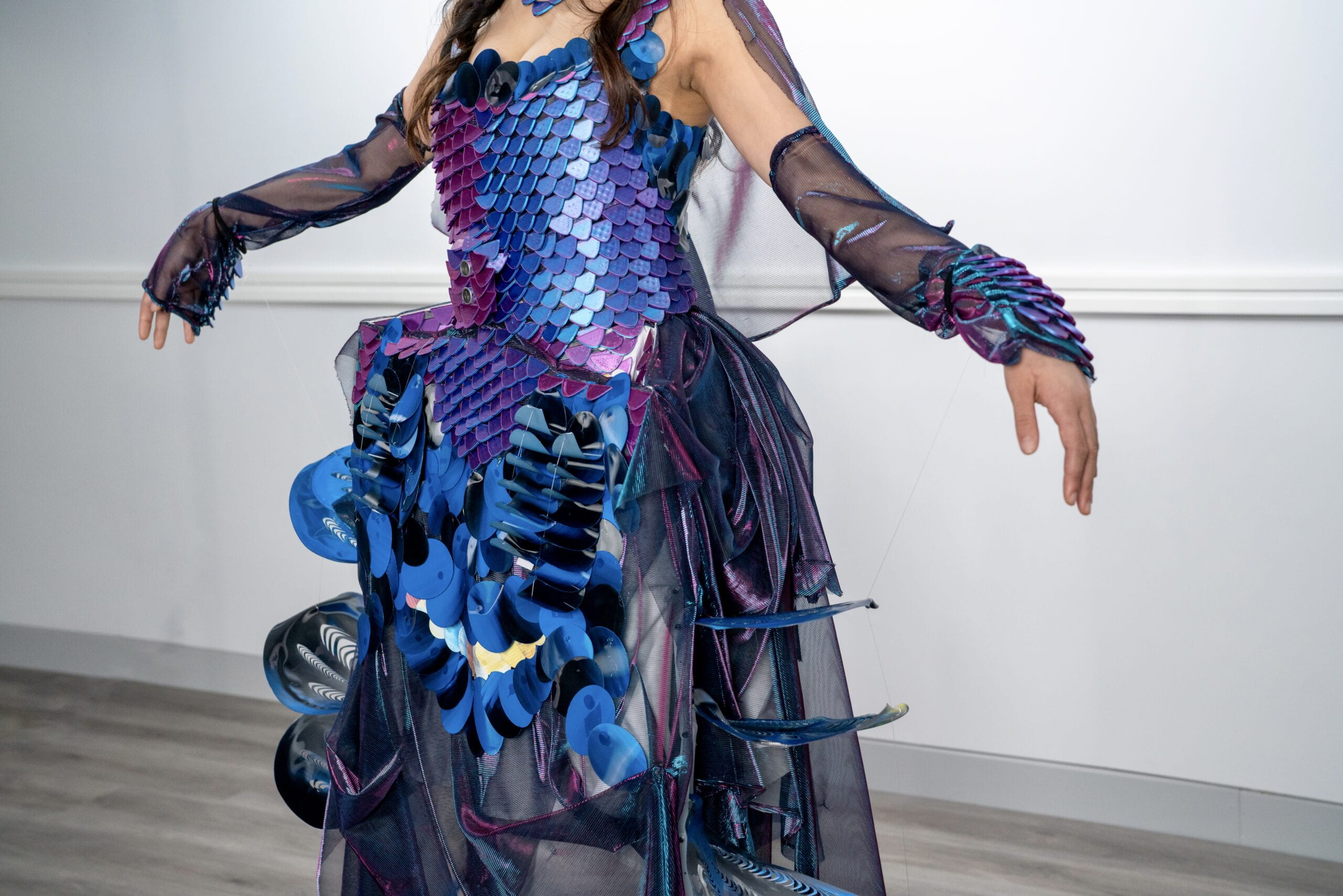
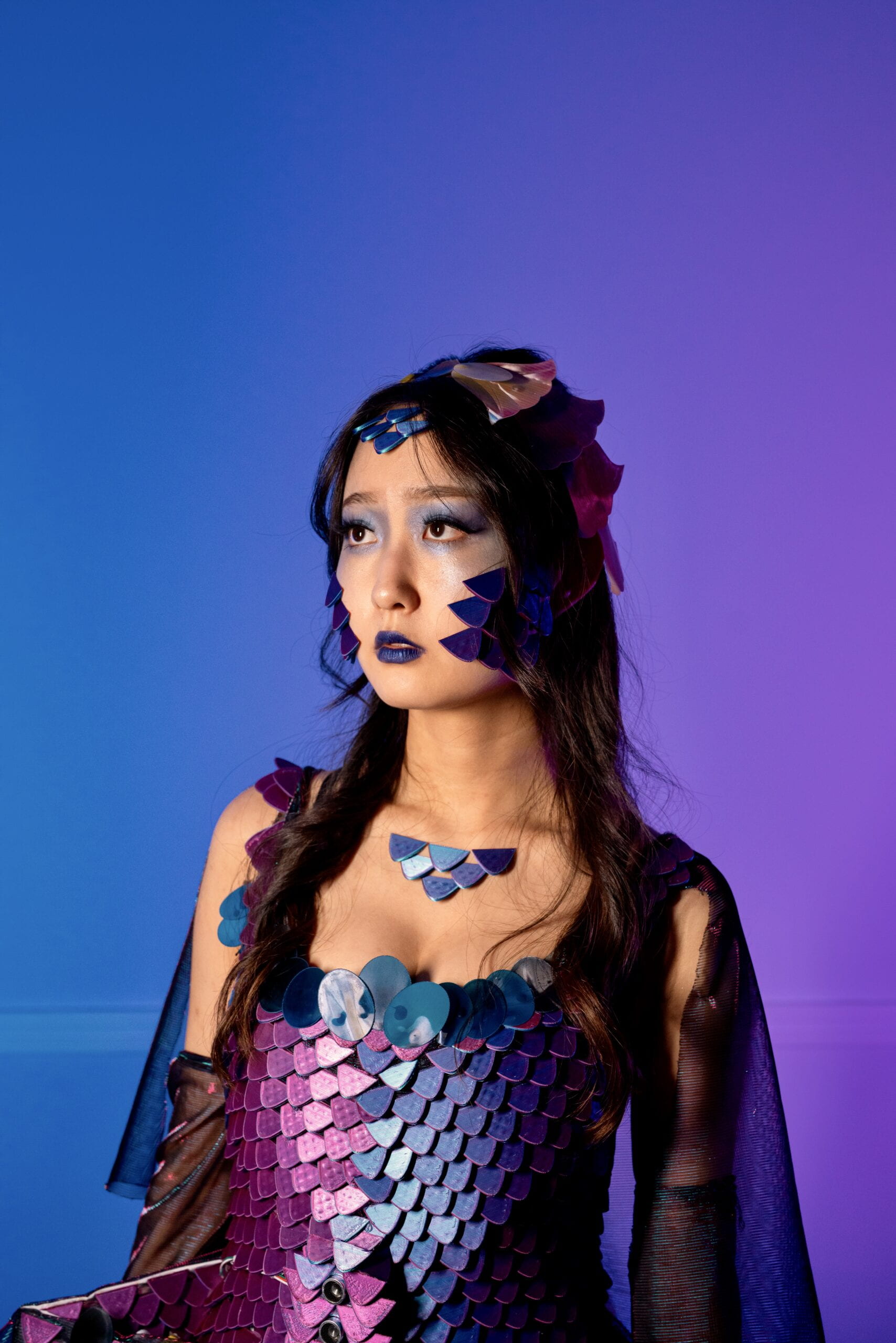
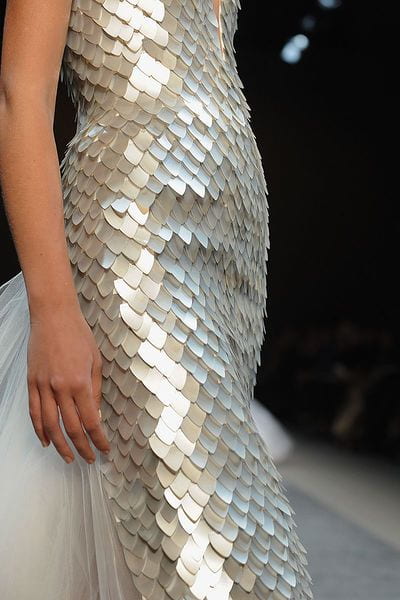
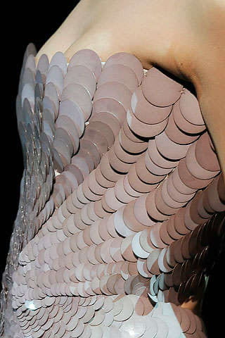
We designed to make a dress that mimic the color and habits of betta fish by utilizing distance sensors to detect the surrounding objects and use motors to role up strings that could pull up and down scales on the dress. We also designed big scales on the side of the body that would be pulled up by lifting the arms of model herself, regarding as an offensive warning of the approaching objects. The other parts of the dress are covered with fish-like scales made from 3D printings and laser cuts, along with blue and purple color fabric that mimic the fish body and swimming movements.

The following sections are mainly focusing on 1) the design and manufacture of dress elements, 2) the moving mechanisms and circuits.

3D Models

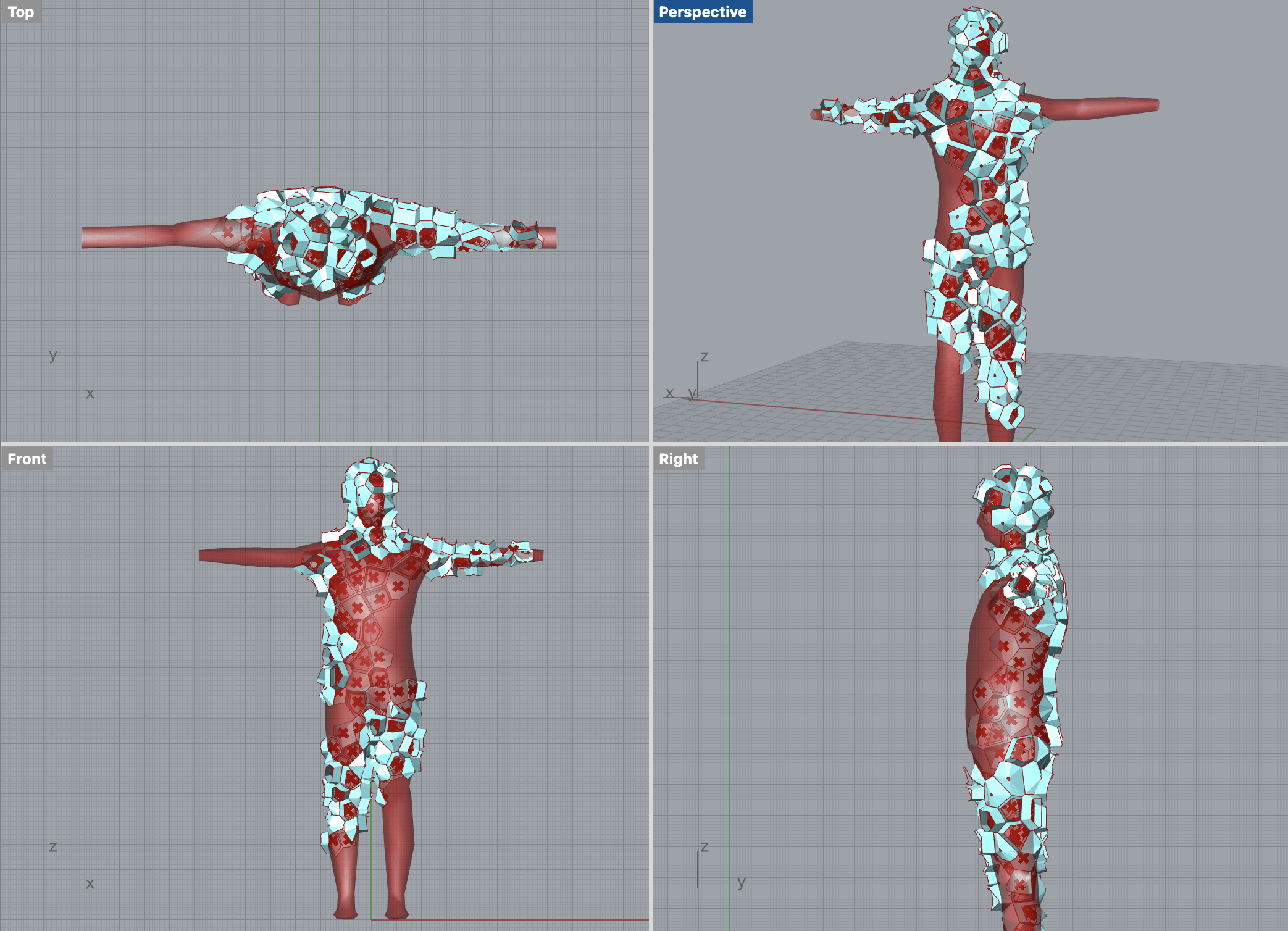
First, in order to make fish-like scales, we utilized both 3D printings and laser cuts. Different techniques and materials are used because that the mechanism uses laser cut TPU scales, however if covering the whole dress with only TPU would be too flat and simple, also not representing the fish scales enough as such 2D scale patterns are widely used besides mimicking fish scales. Therefore, we decided to also make 3D fishing scales and put them onto the dress.

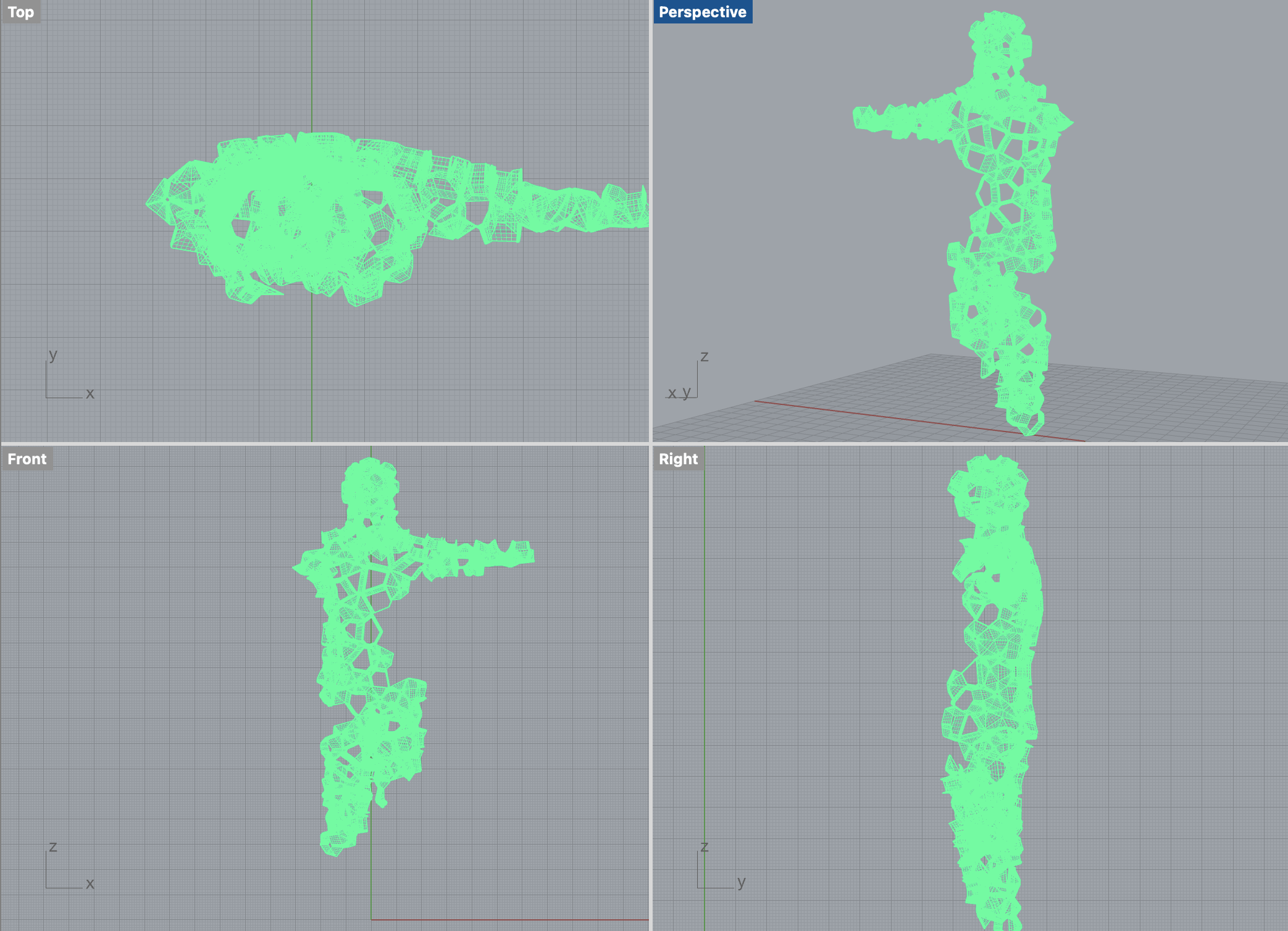
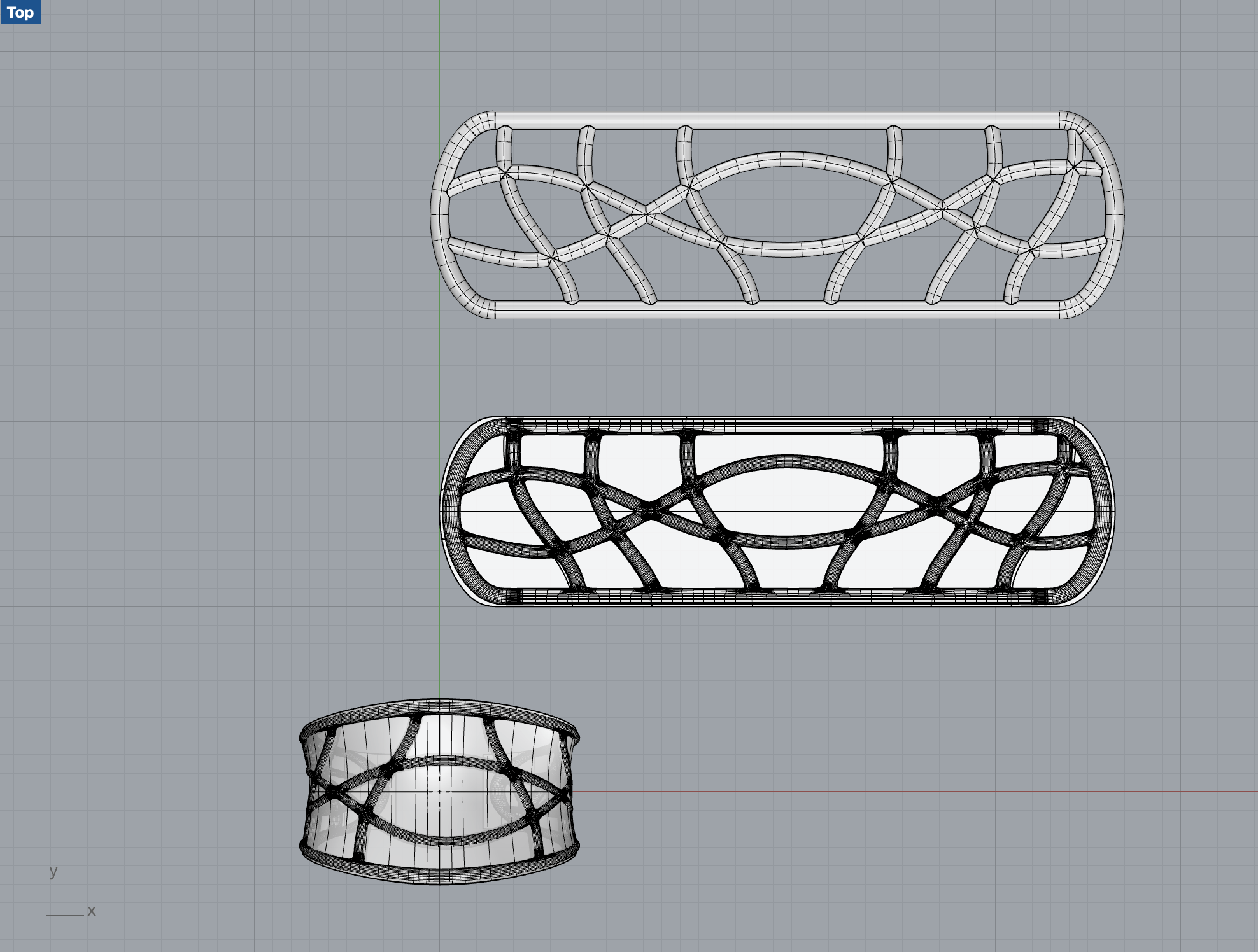
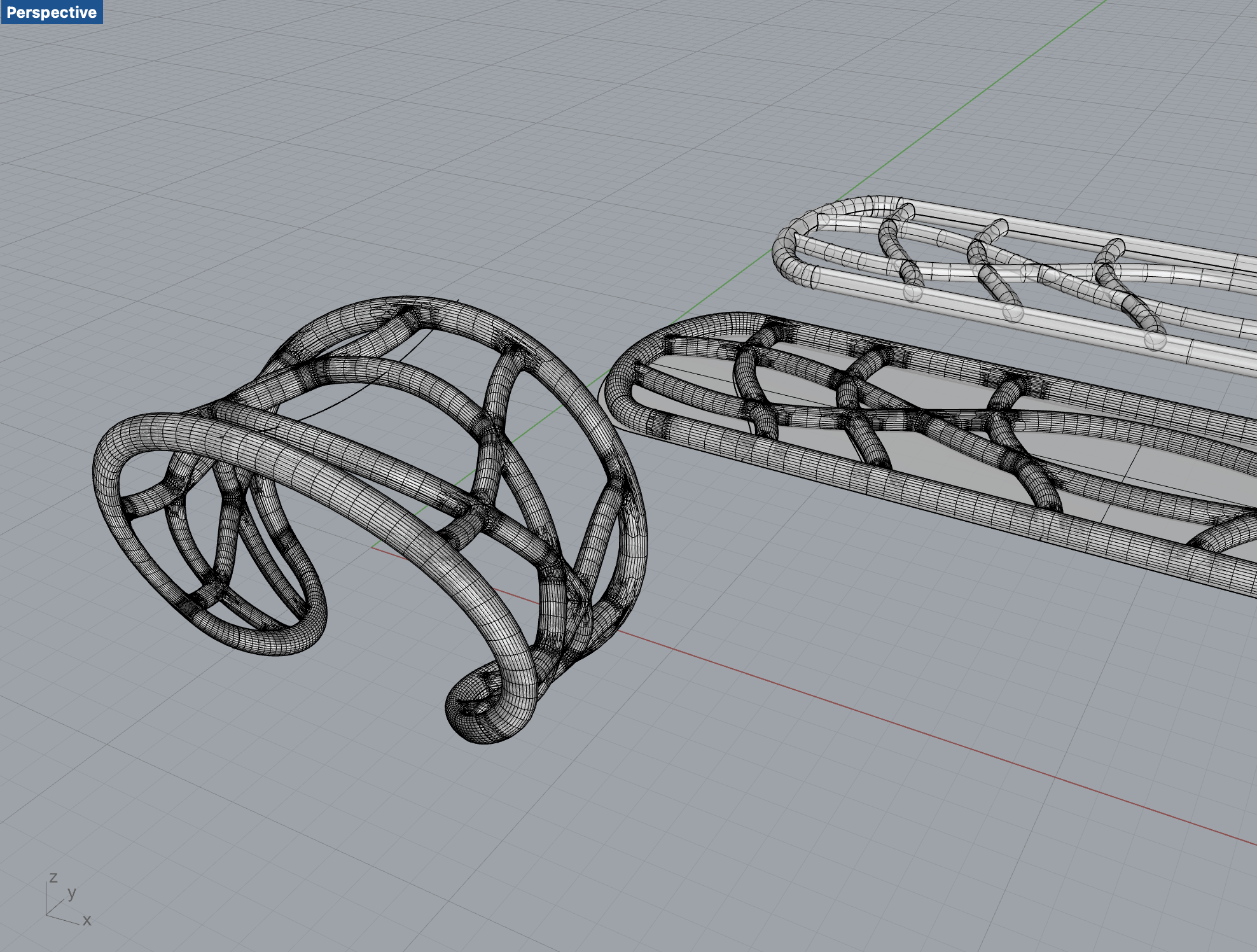
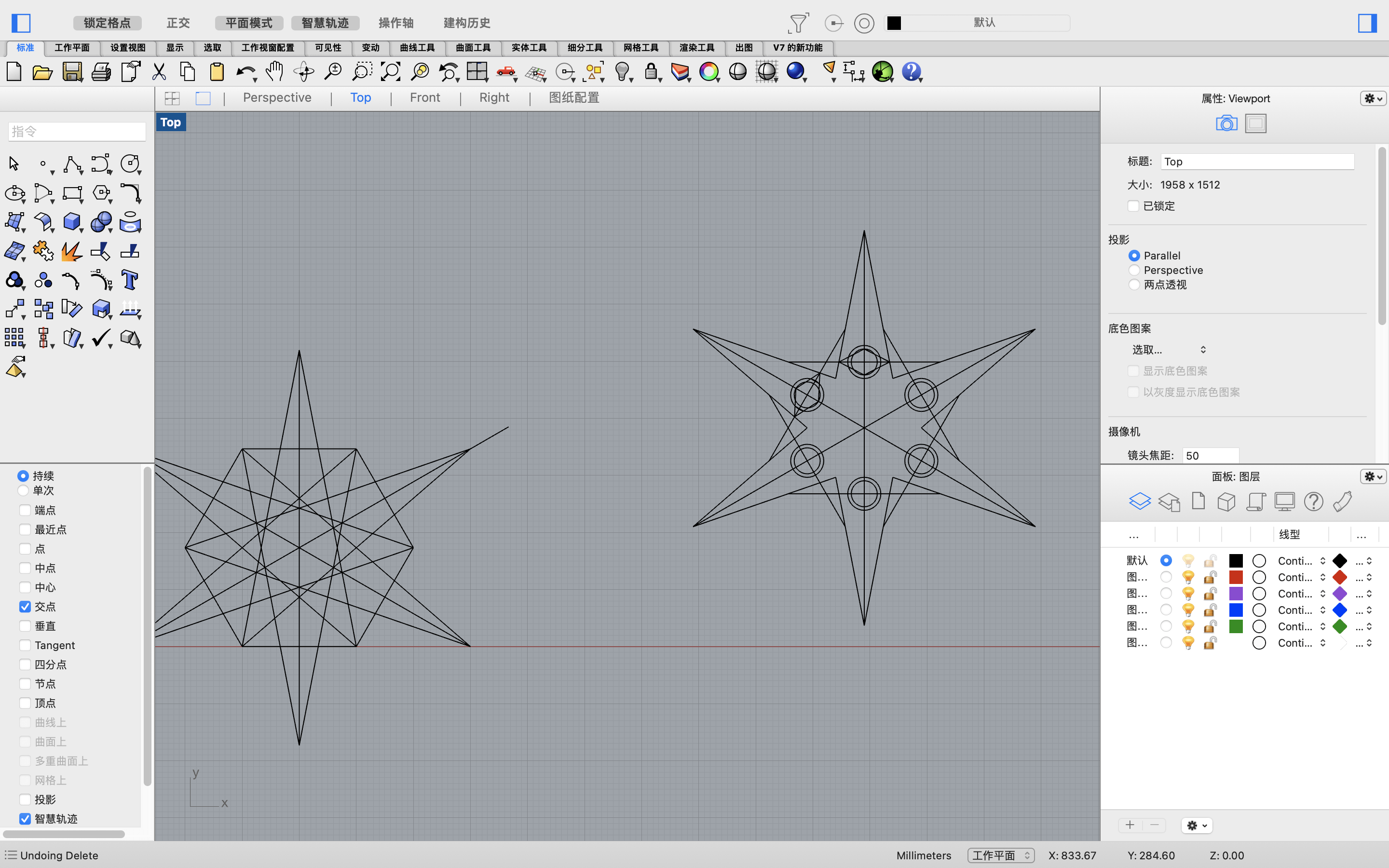
Continuing from what I did in the last assignment, I had two kinds of 3D models for scales, one is dragon scale and the other one is self-made hexagon based scales. However, neither of these two models resembles the real fish scales exactly. As fish scales are not so angular and sharp.

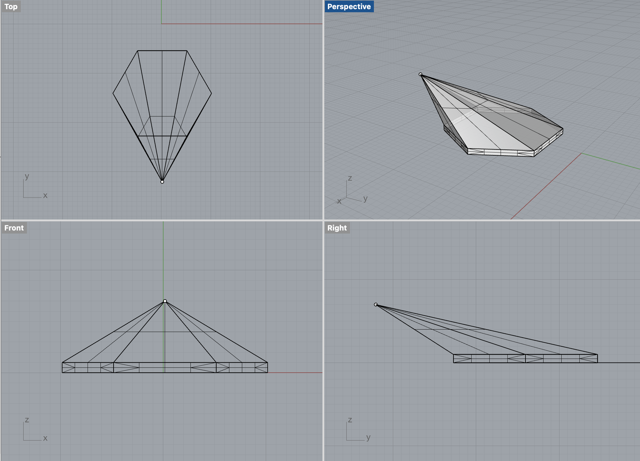
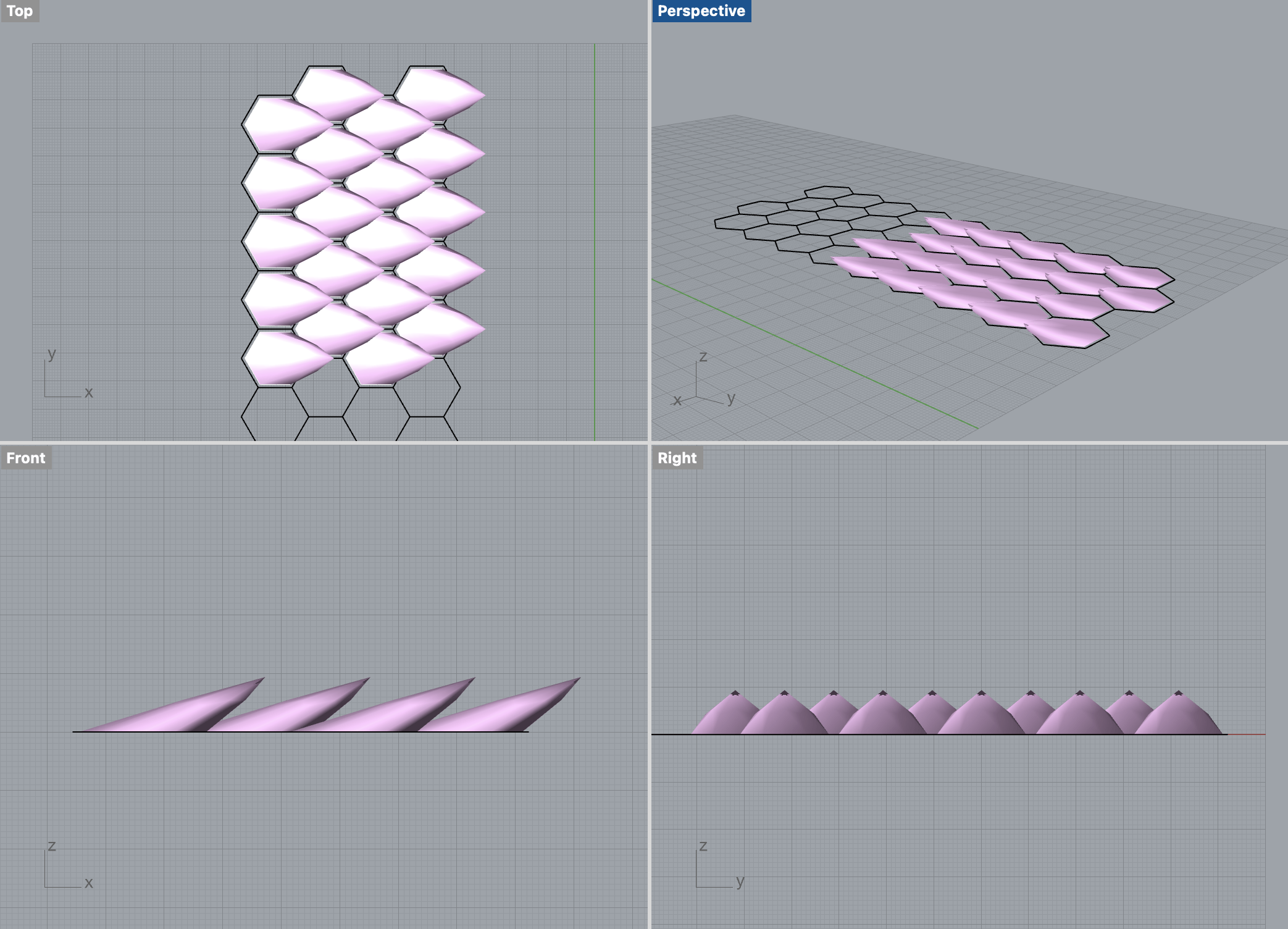
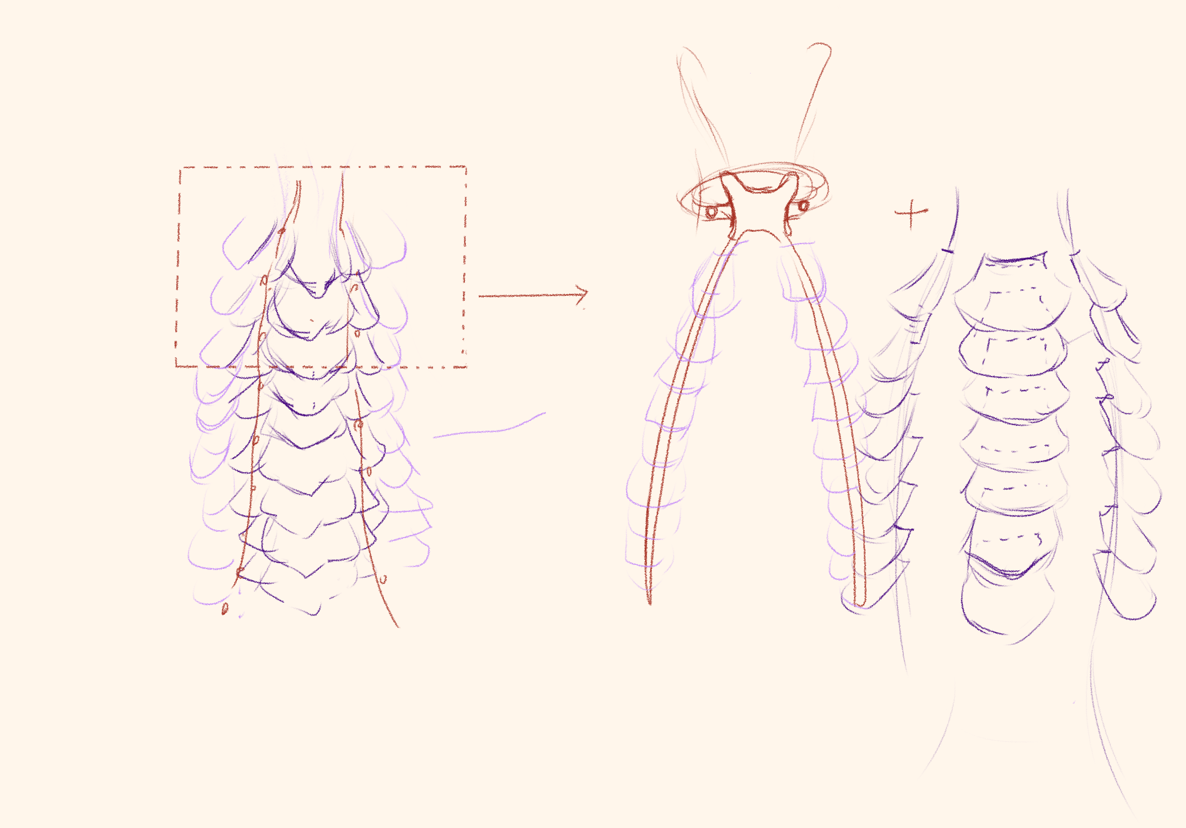
I first though about making the scale angles and edges softer, however, that method did not really work out as the outcome looks even less like scales. Then, after discussing with Professor Marcela, I found that semi-circular shape resembles fish scales more, and Professor told me that instead of making hexagon shaped base, I could use simpler block shaped base to line up the scales, as the base for semi-circular shape scales are merely triangles, which could be perfected alined with block shapes.

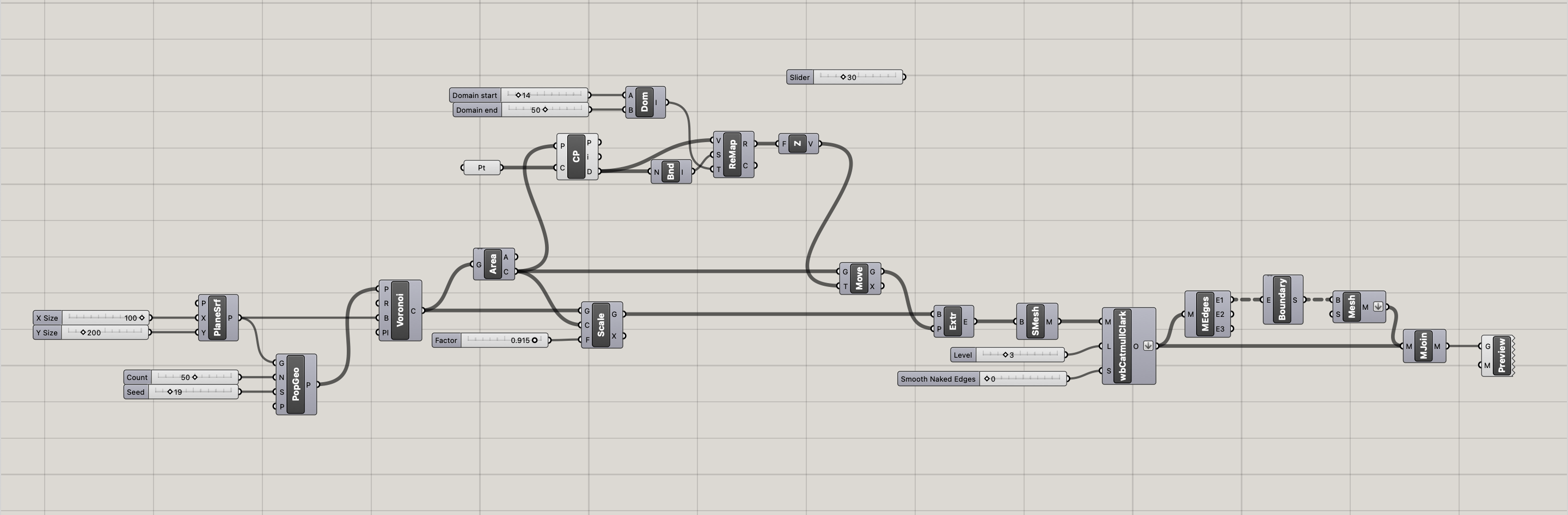
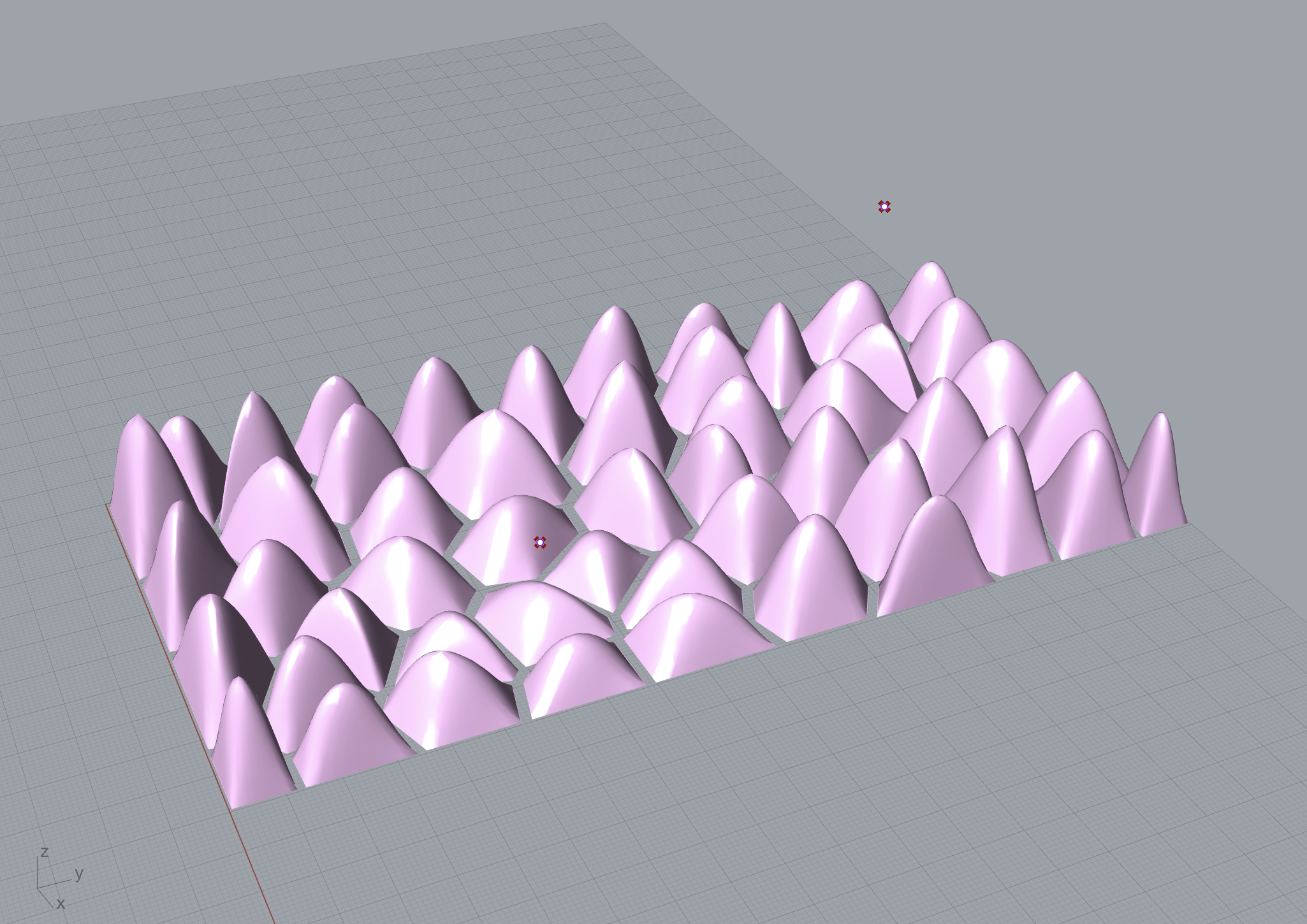
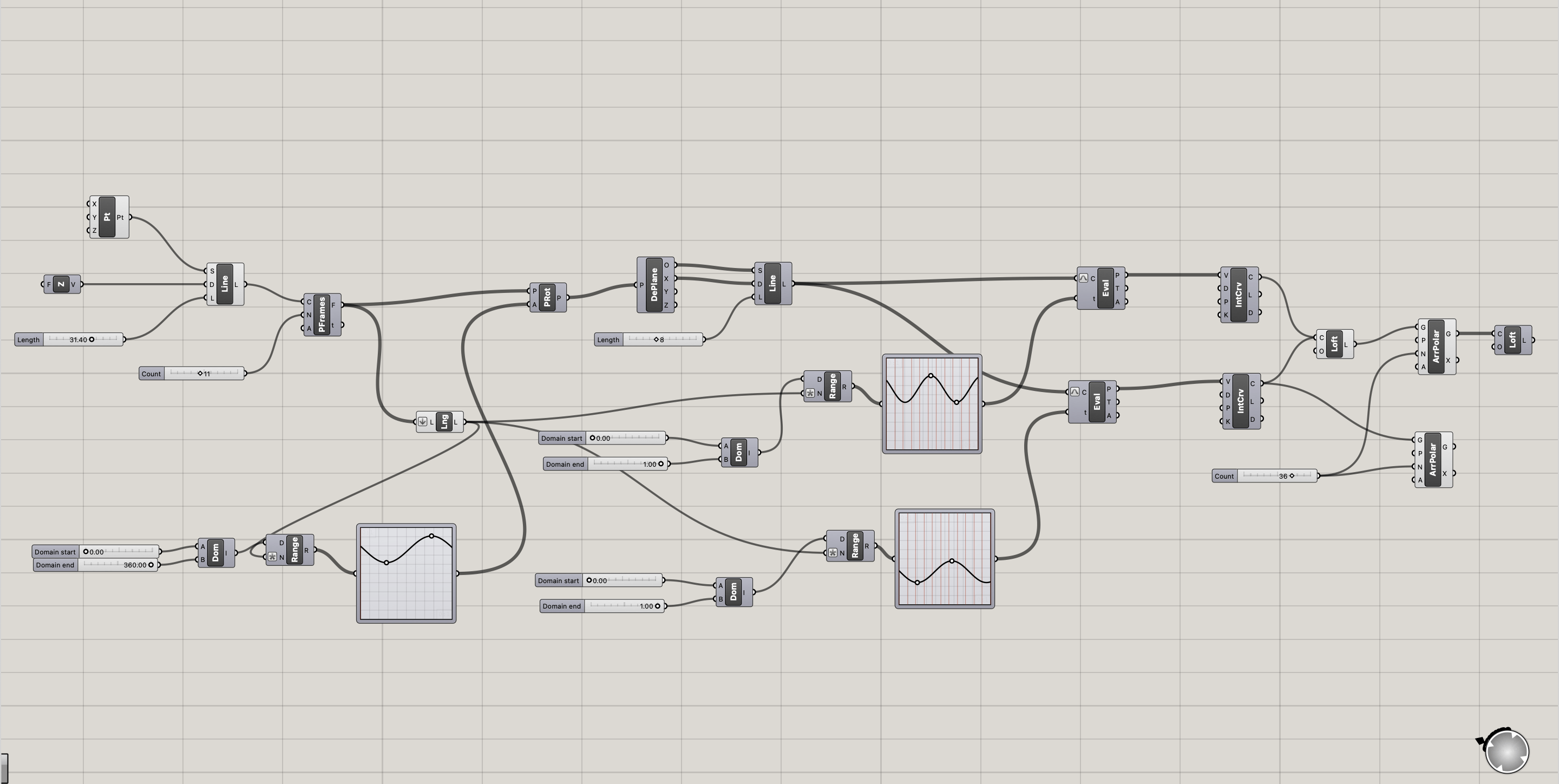
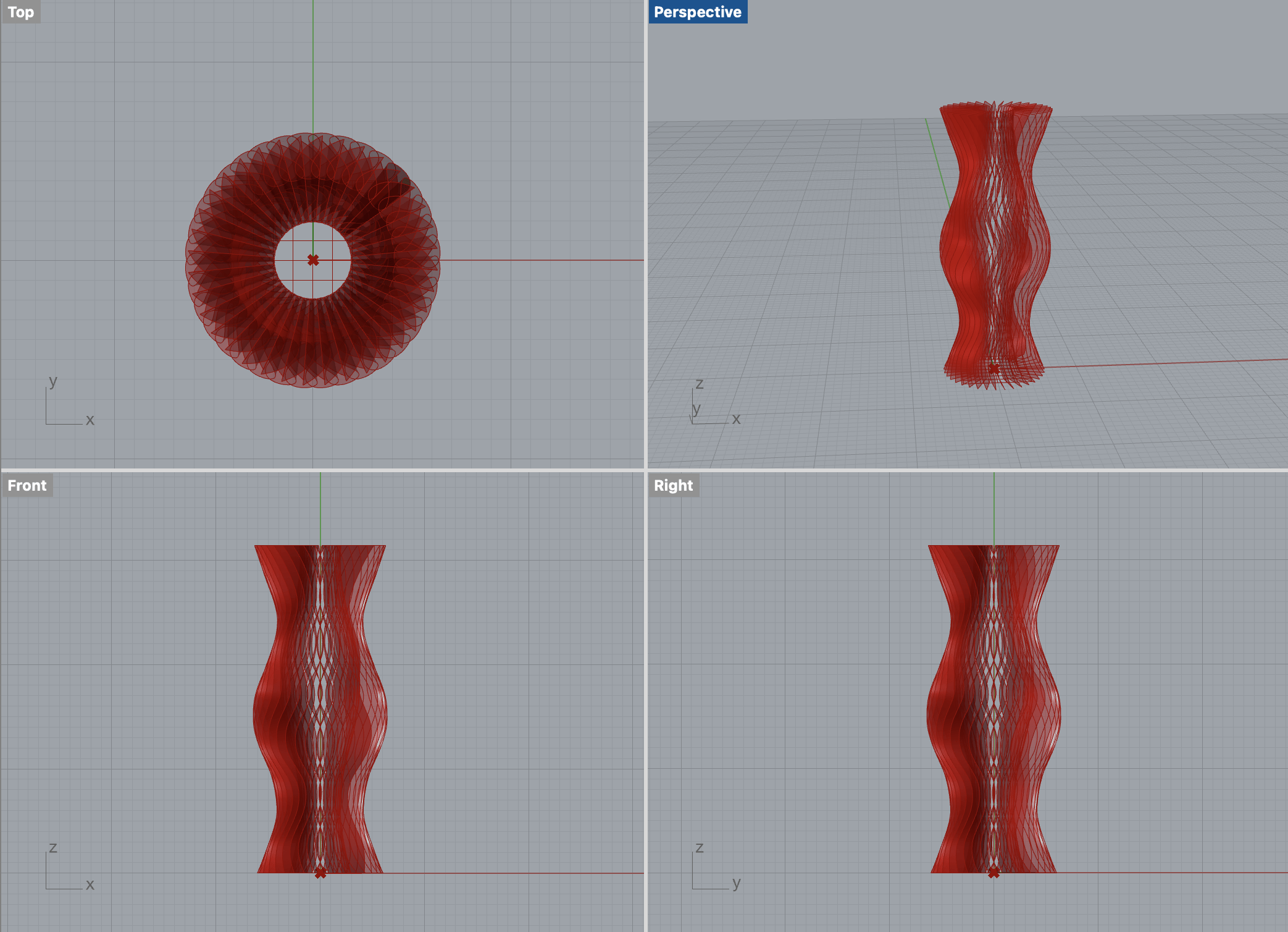
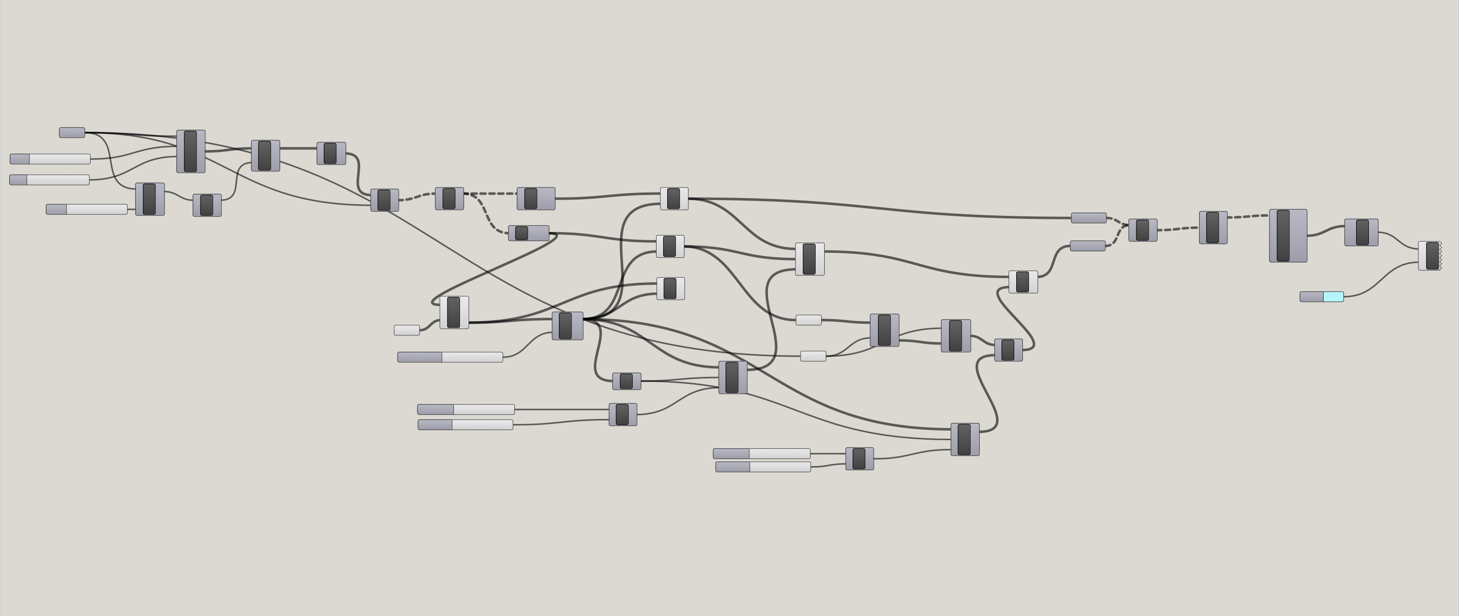
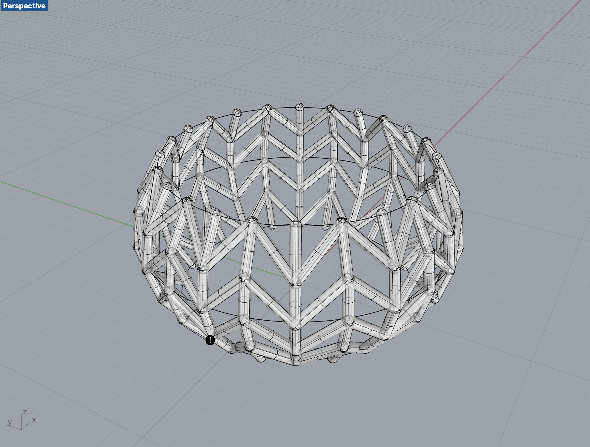
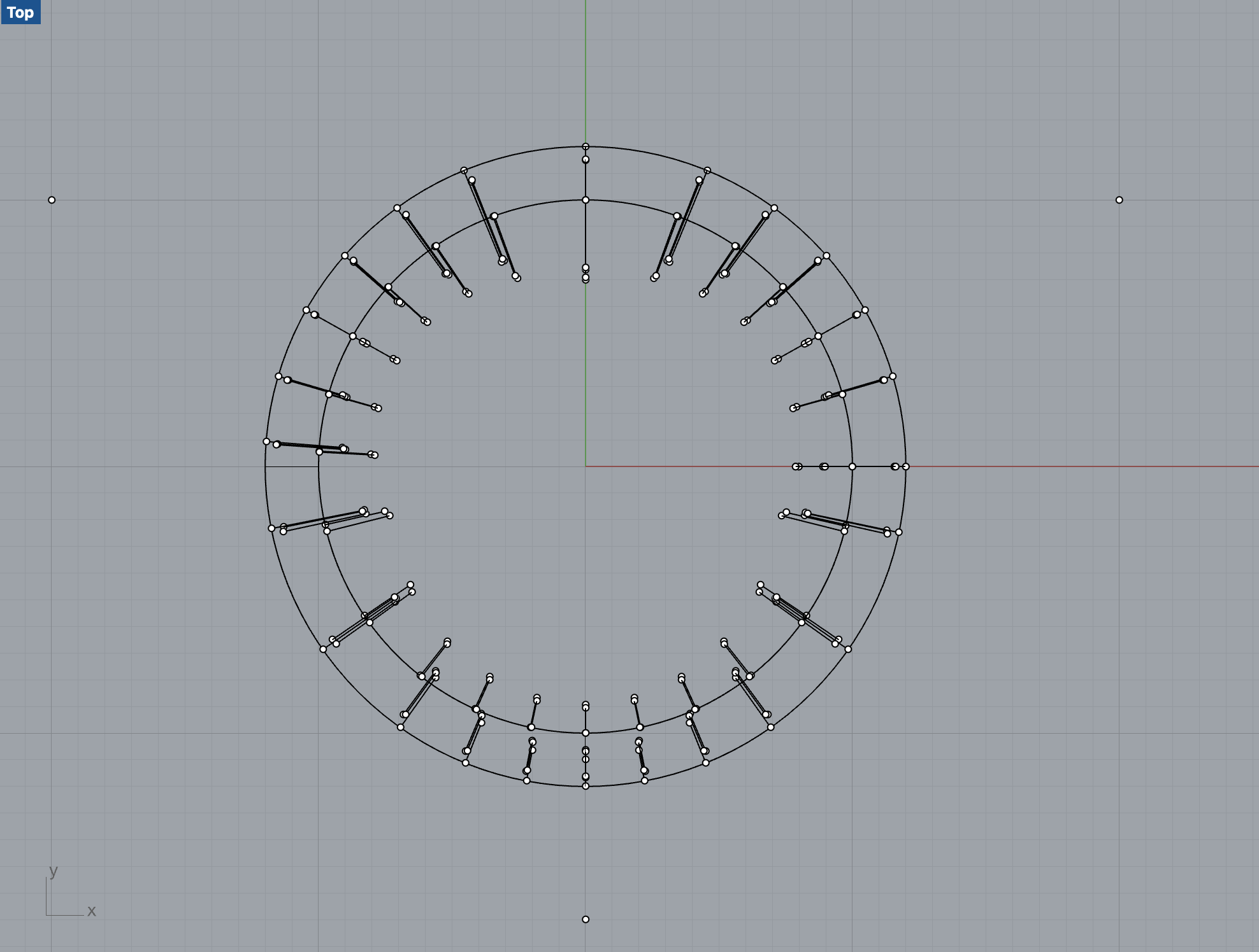
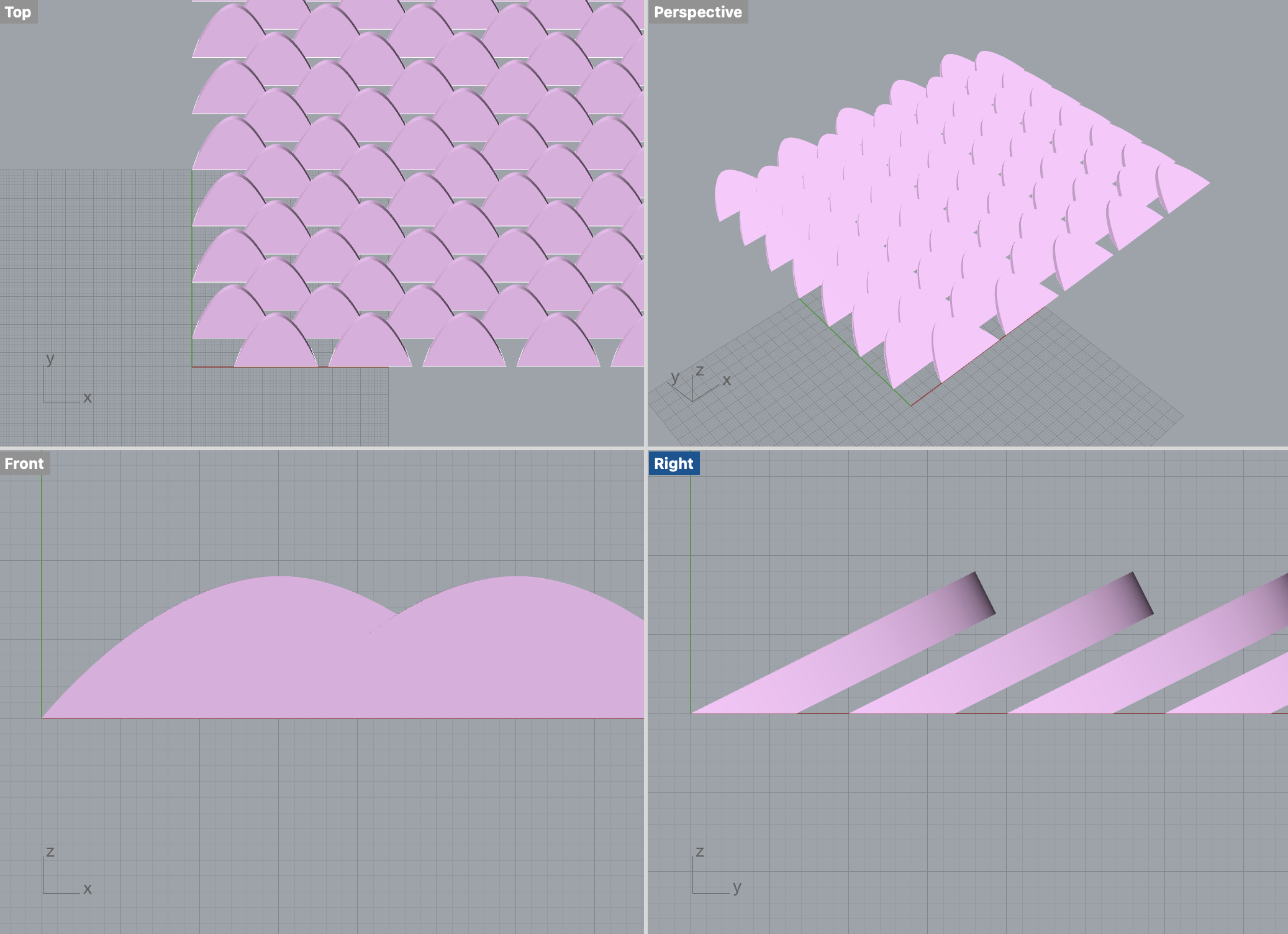
After figuring out the shape we want, I tired to create such model using Rhino, however, with my relatively poor knowledge with Grasshopper, I did not really figure out how to aline multiple scales together. And that’s when Professor Marcela provided me with a complete Grasshopper logic that models exactly the shape we want, along with parameters to change the size and distance.

Thank you Professor!

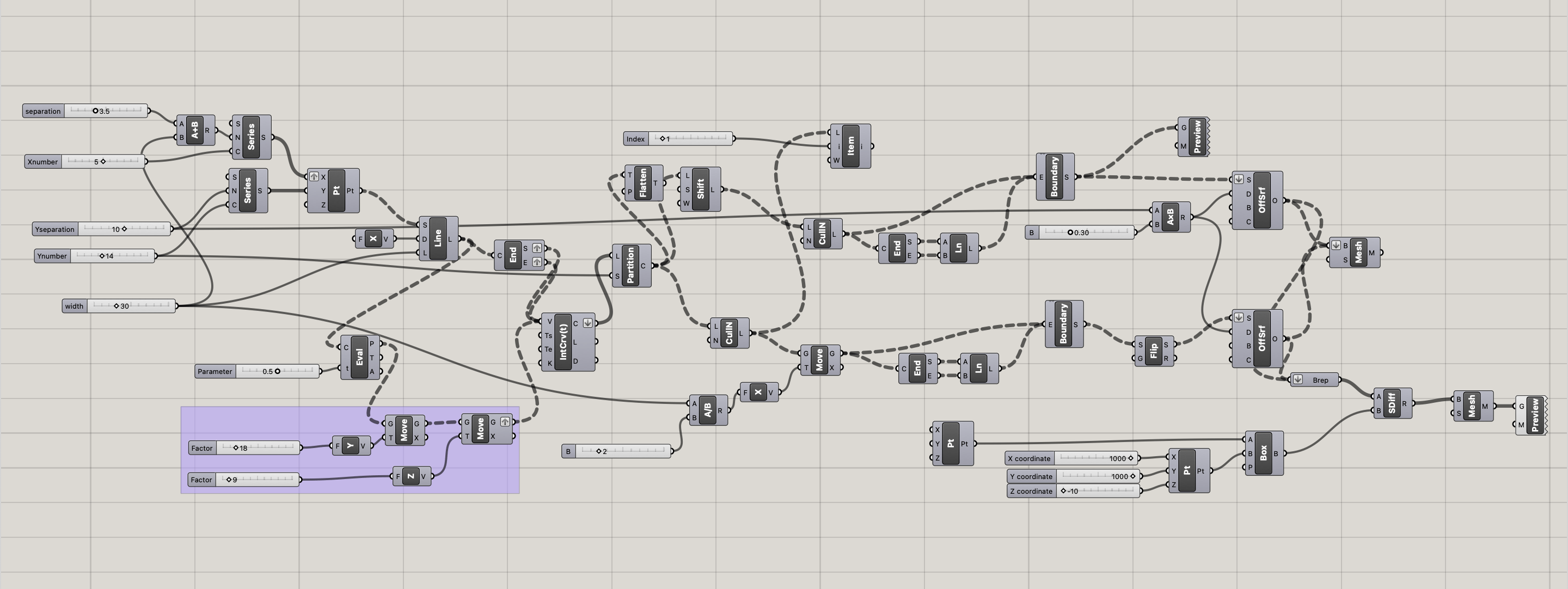
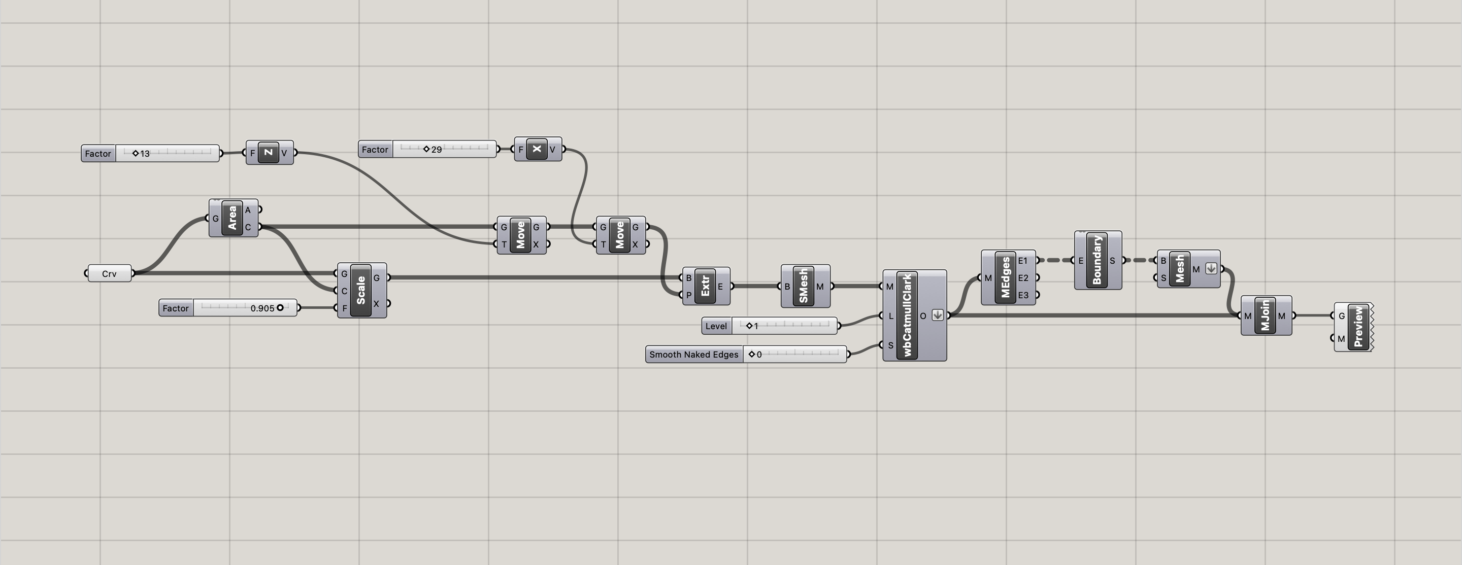
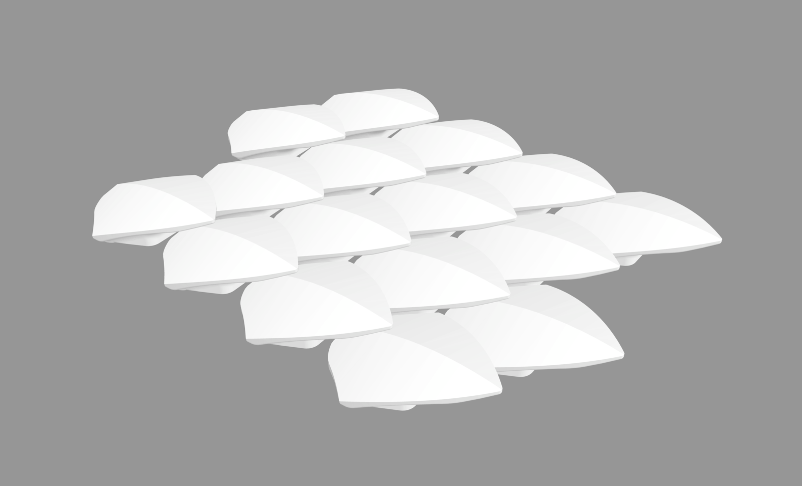
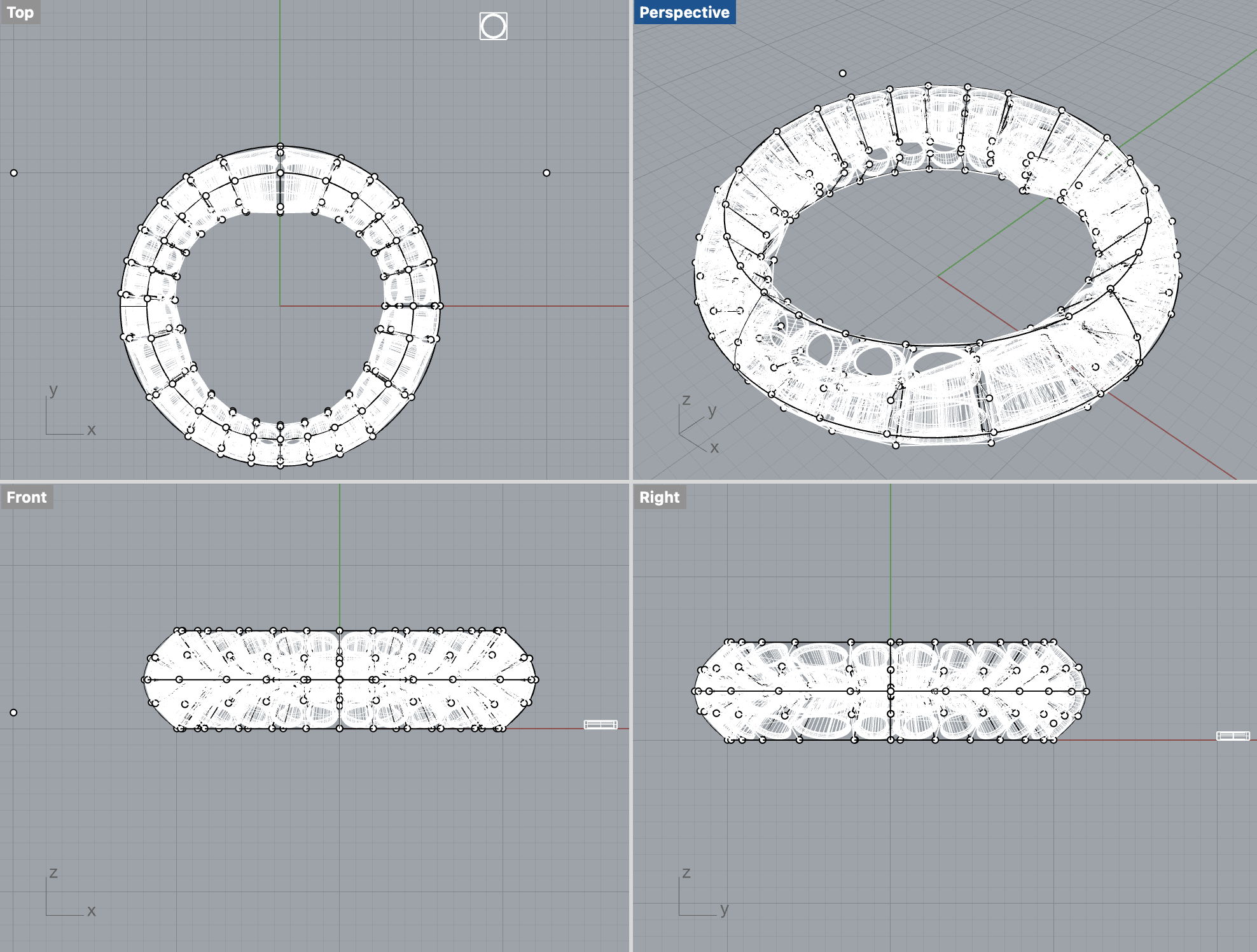
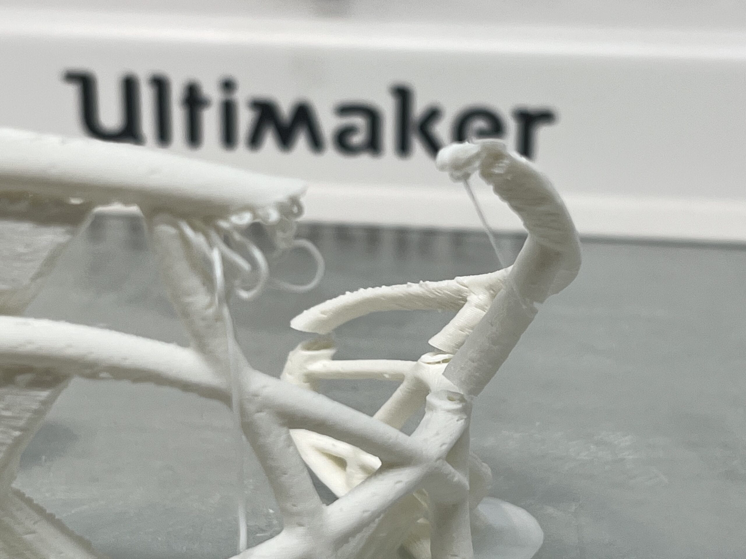
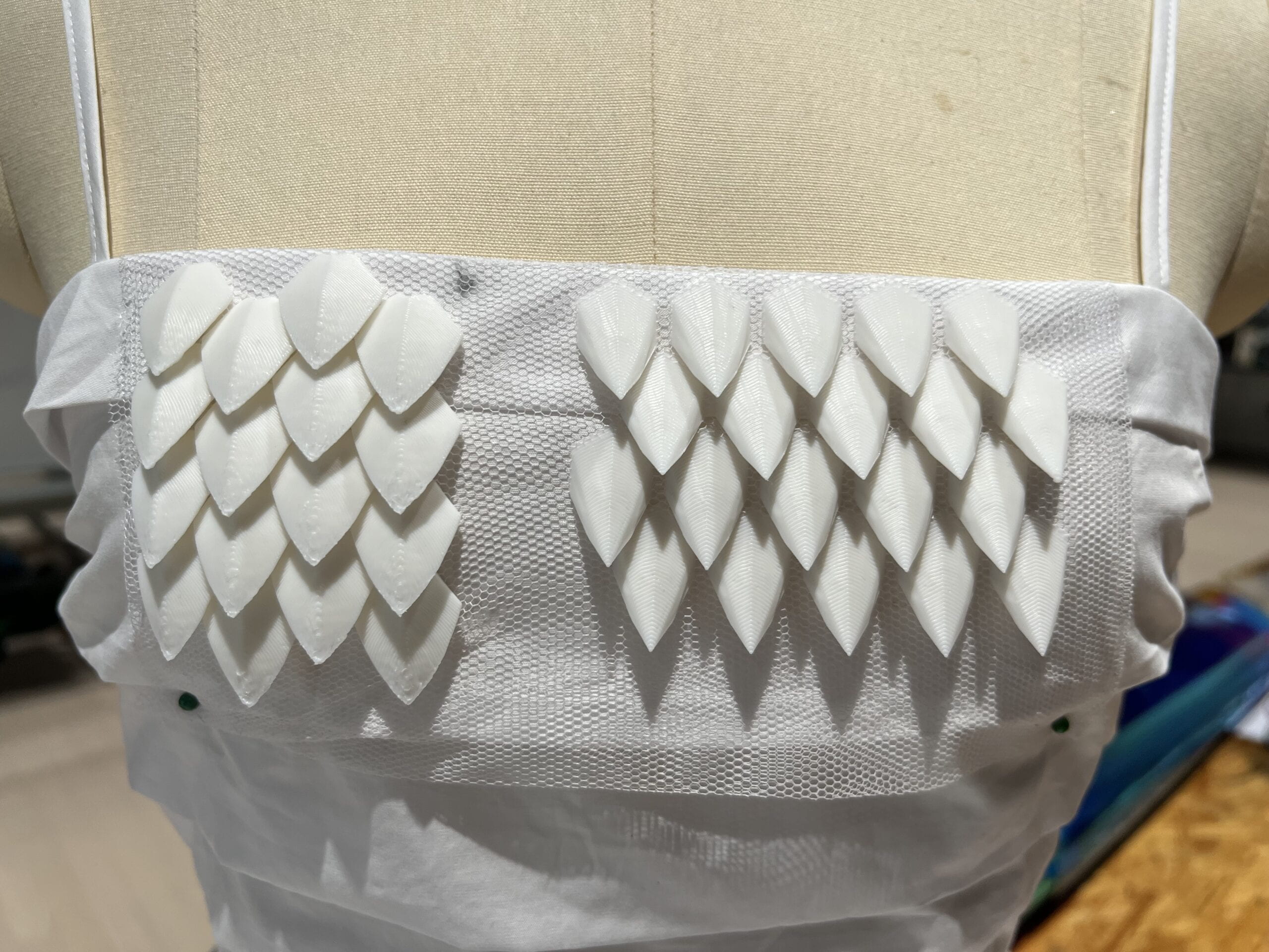
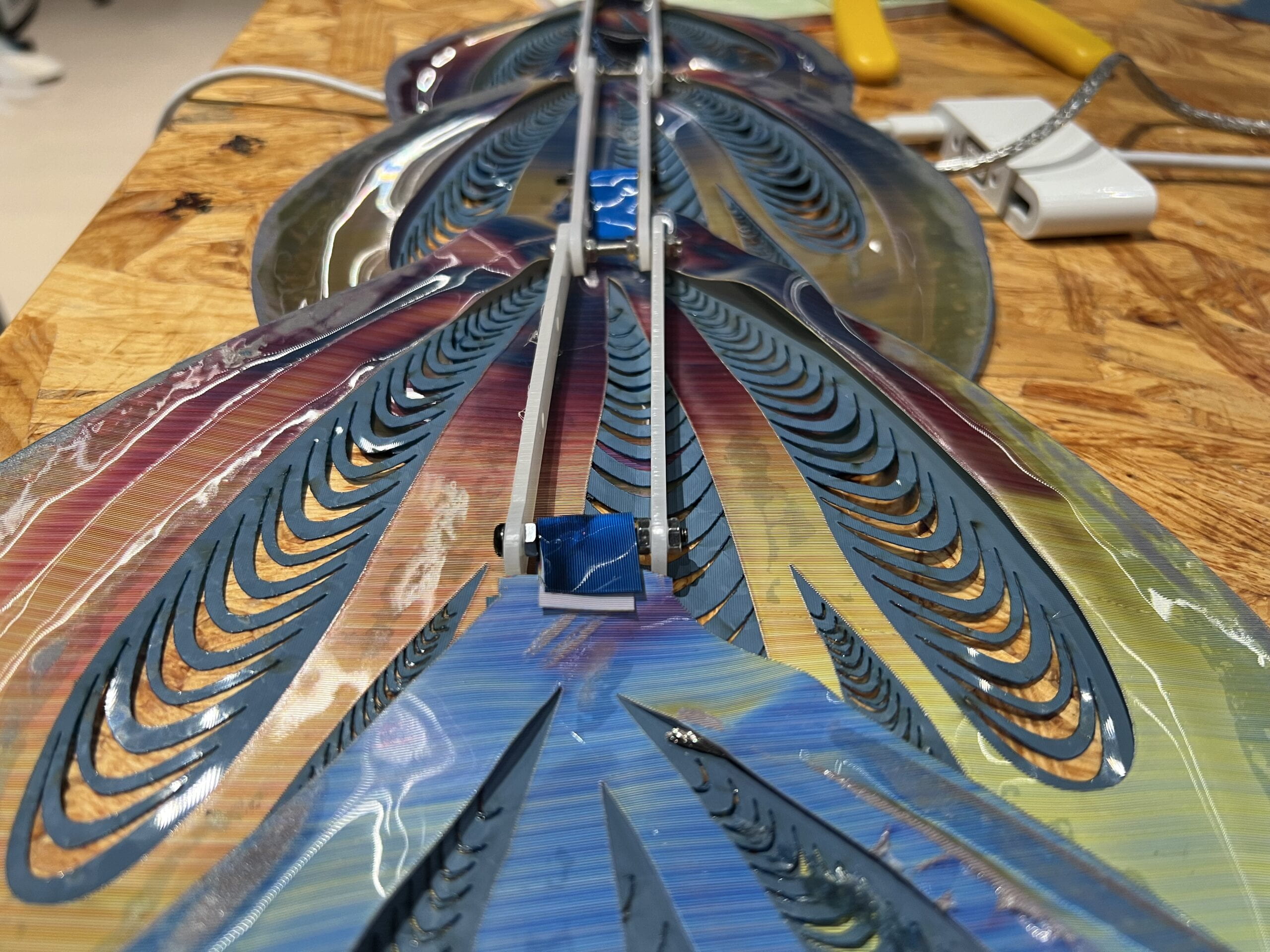
Then, I added the y-axis movement to have the semi-circular scales not pointing up but leans to a certain angle that overlaps a little bit. After that, I 3D printed the scales to test if it works. I also made some small adjustments on the parameters in later works to scale down the size and prolong the distances a bit so that the fishing scales look better and could be “twisted” with farbic.

3D printing

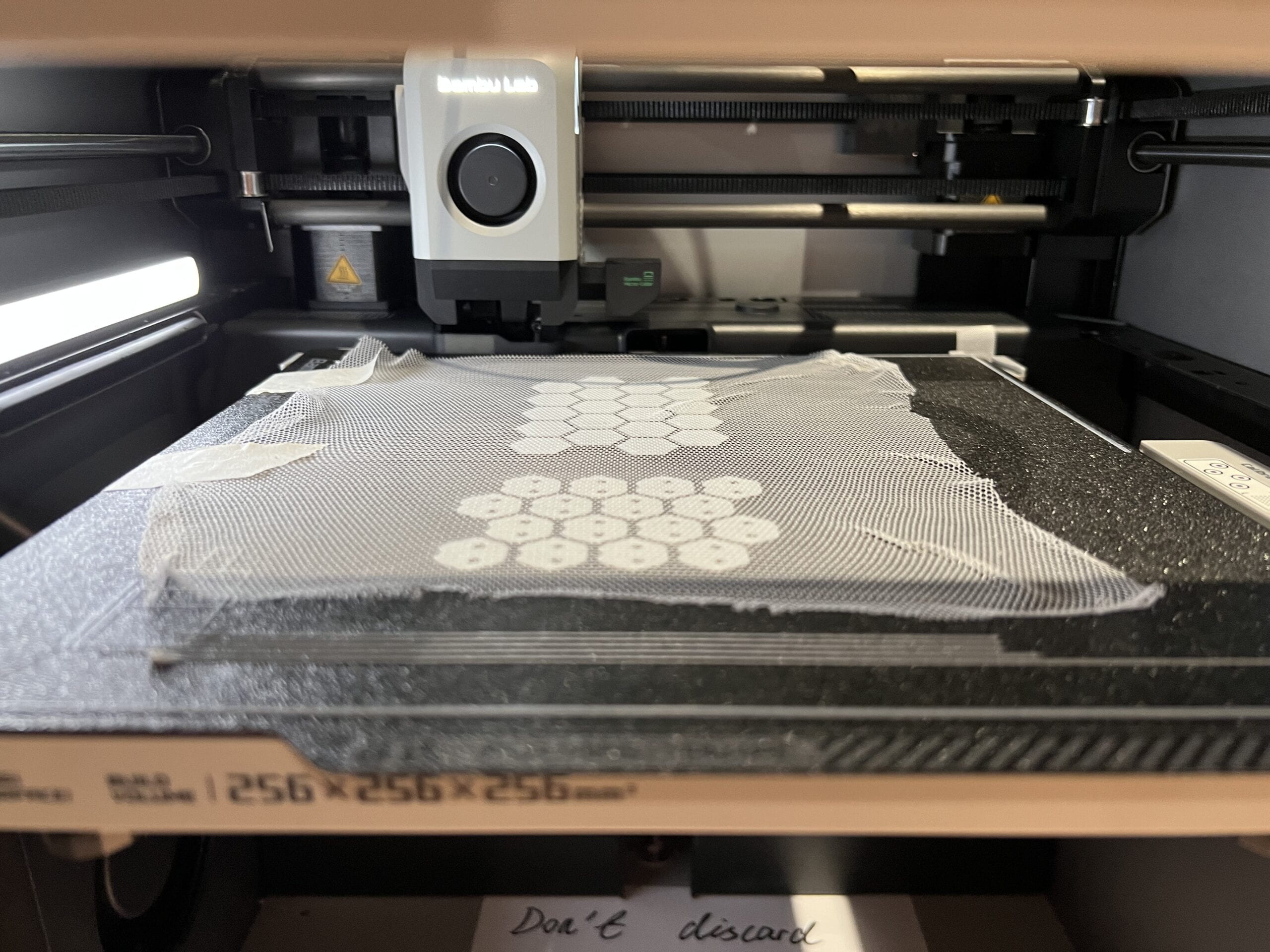
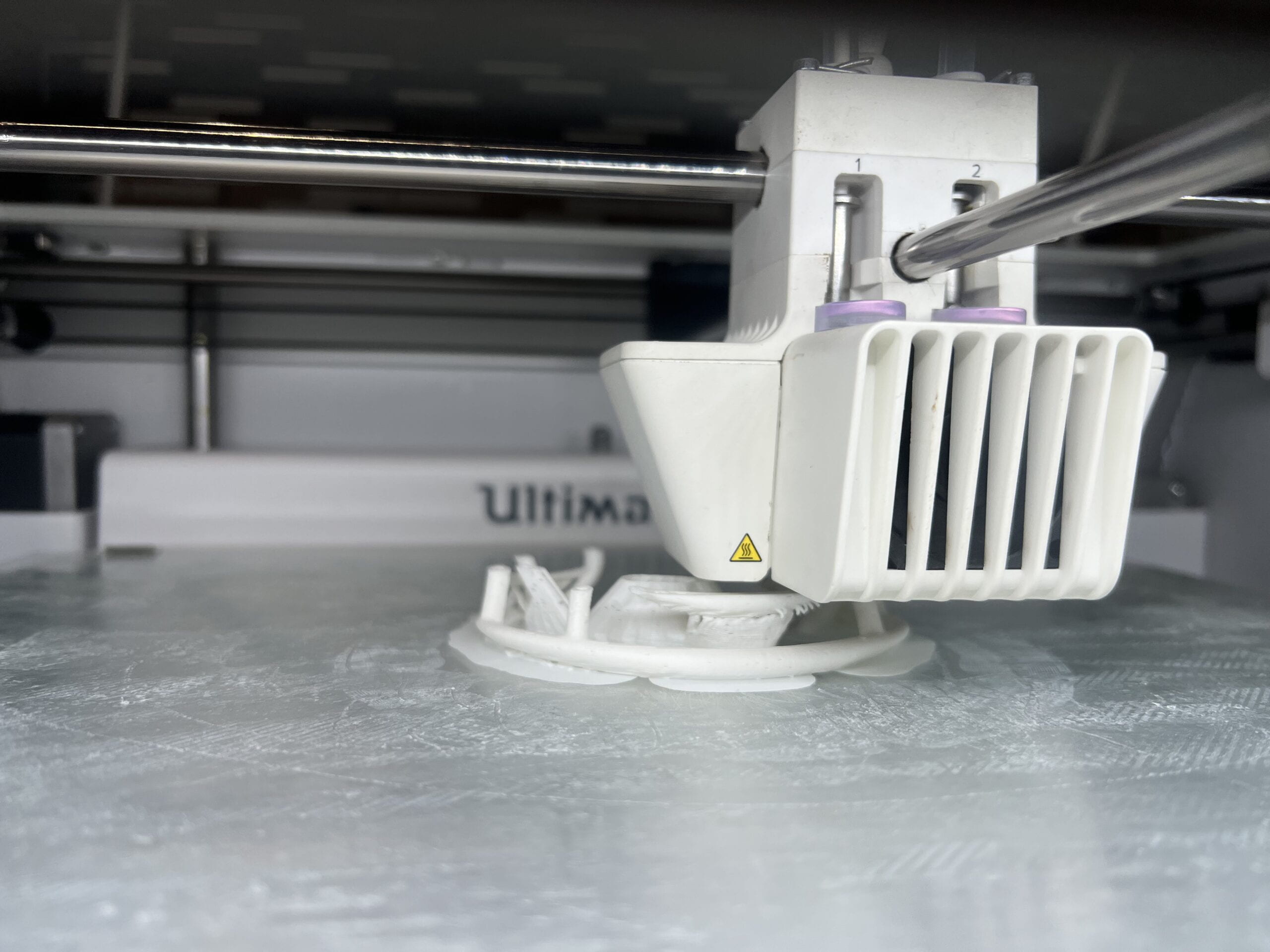
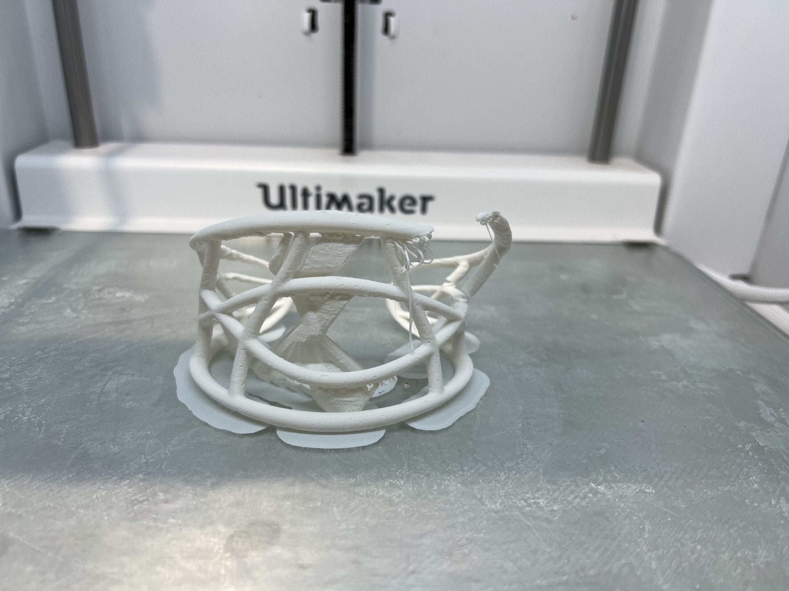
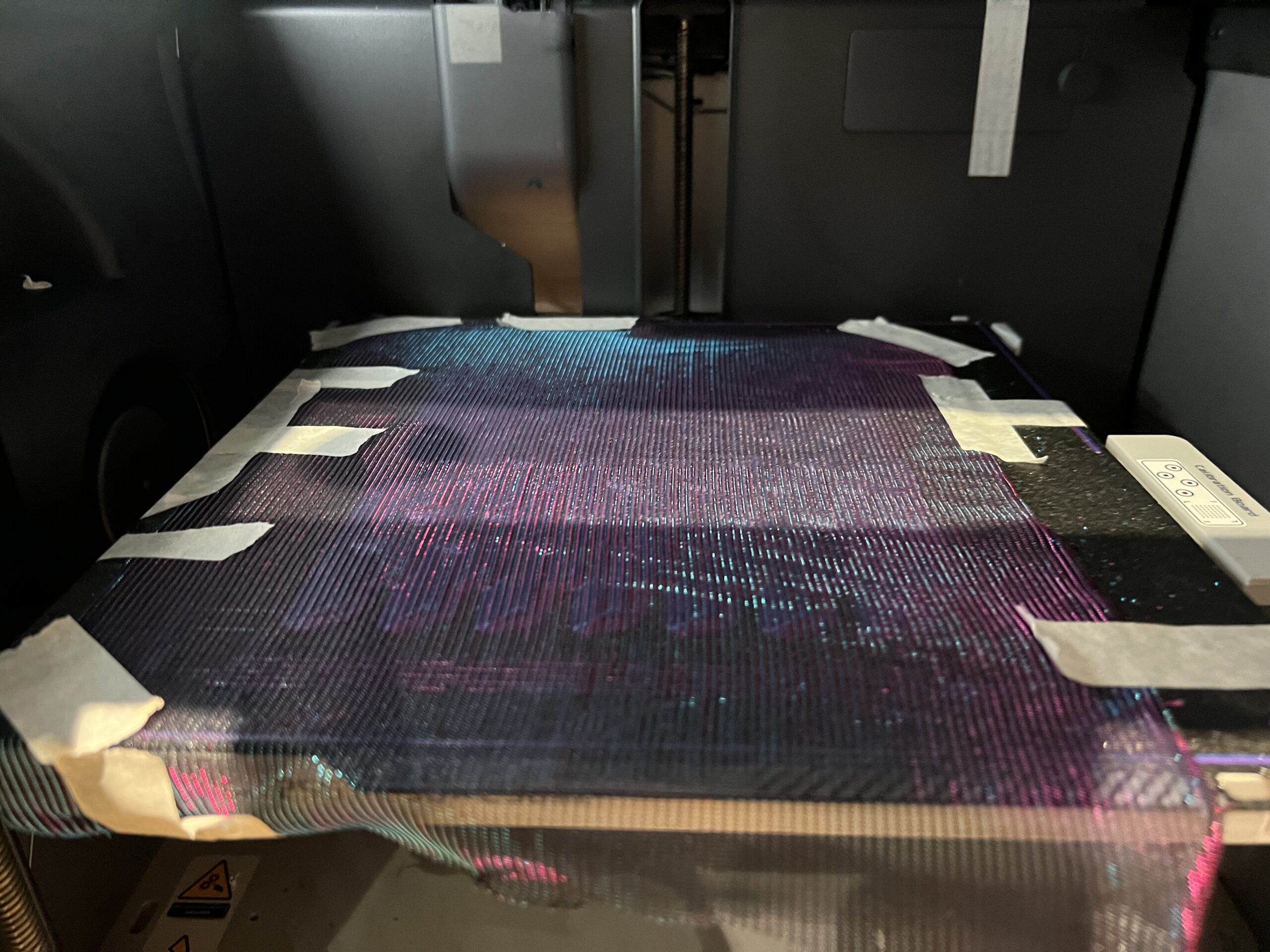
After getting the 3D models ready, I started printing them right away. I first did several test rounds to see if the shape can be printed without using supports and if can be printed on other fabrics (other than the transparent one provided by Professor, as we wish to have scales on the blue purple color fabrics).

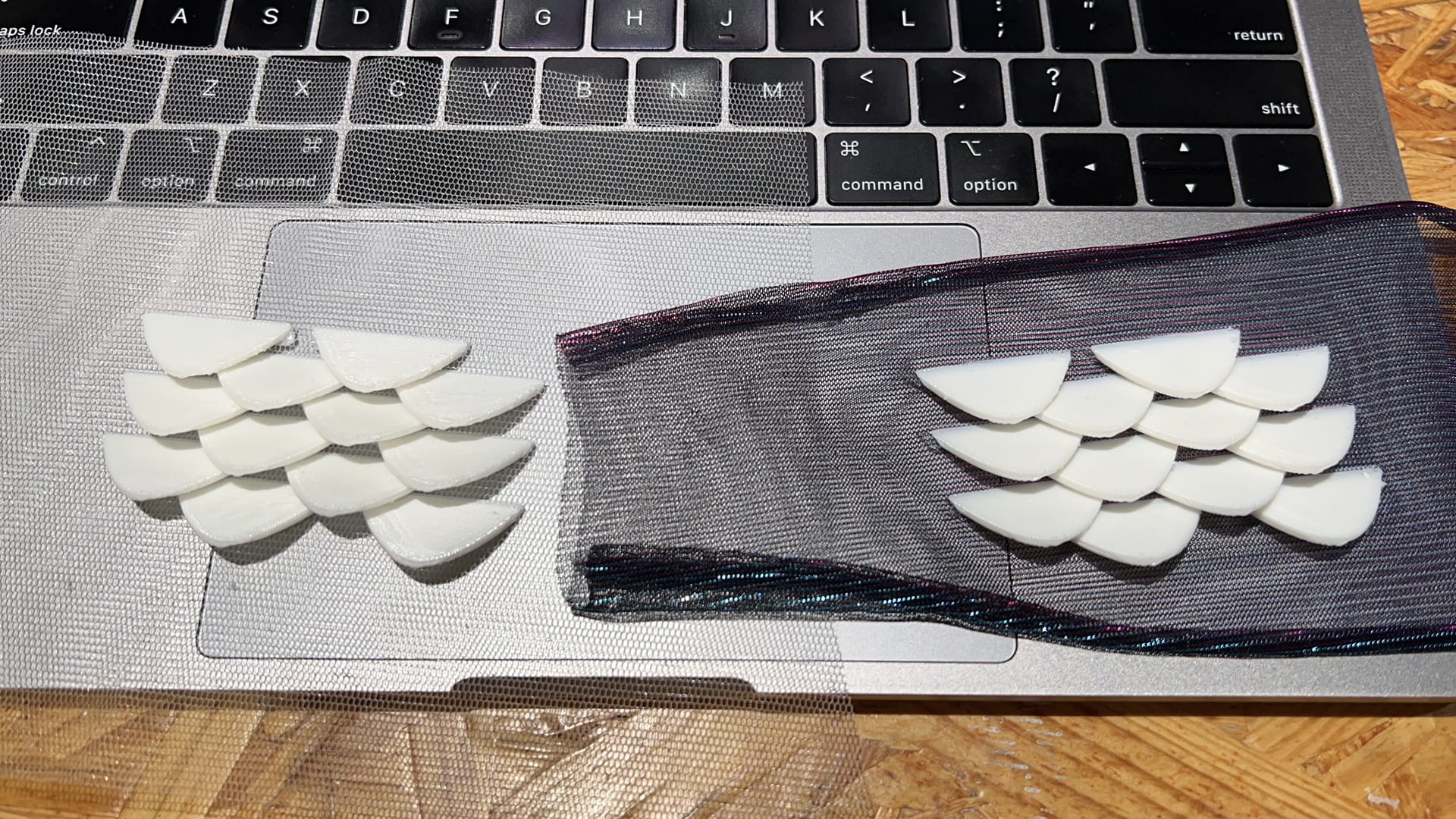
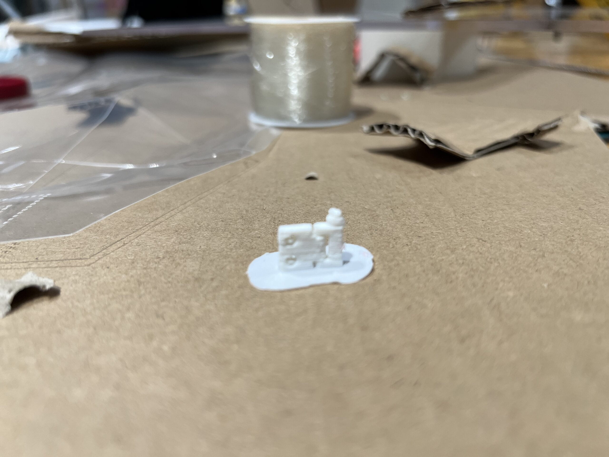
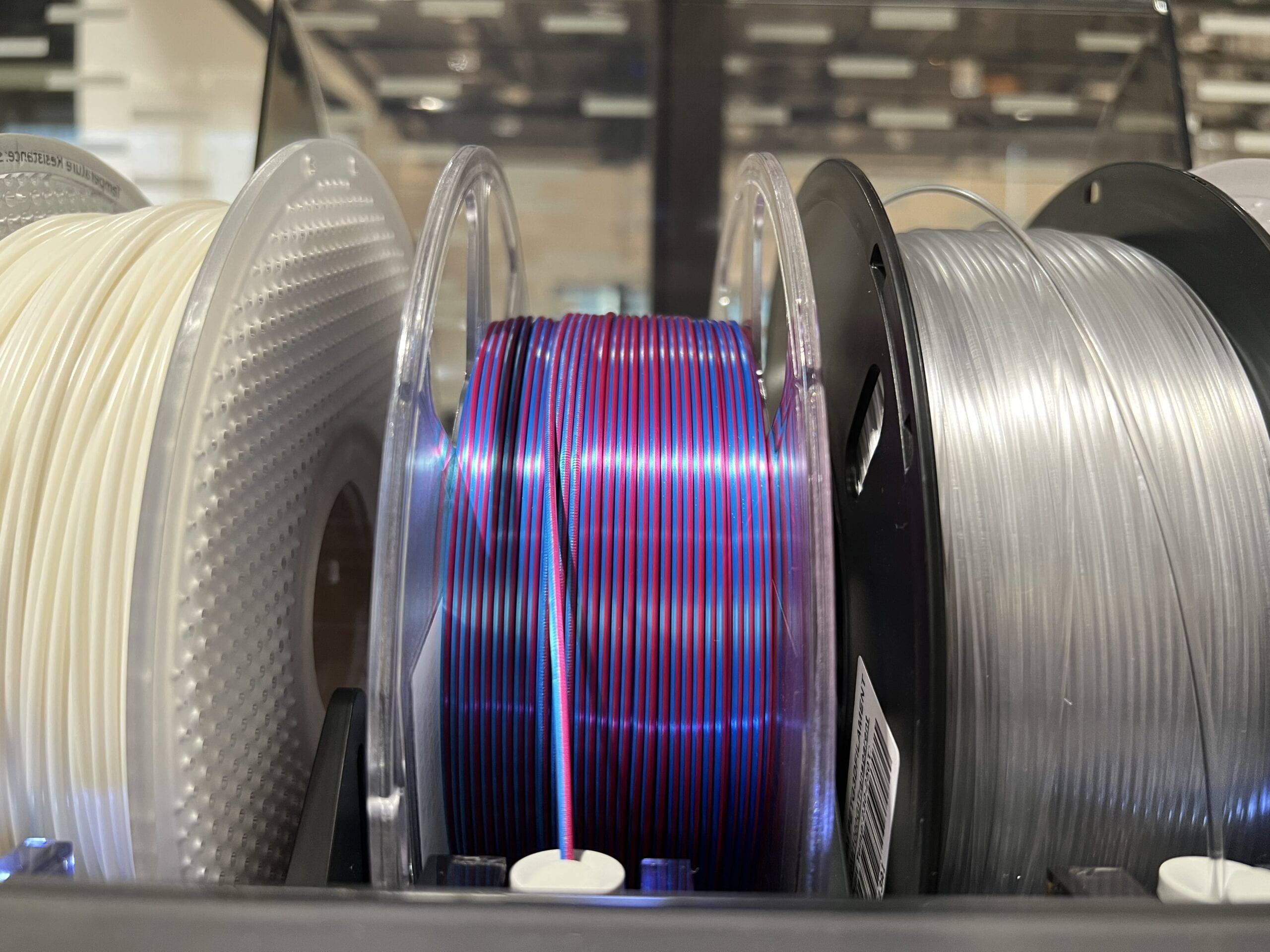
It turns out that both the model and the fabric worked really well. The next problem was with the color, as the 3D printing materials usually comes in white, black, grey or transparent. We thought about painting them into blue color. But Professor Marcela offered we a great solution, the gradient color PLA. Such PLA has a combined color of blue and purple, so that the printed objects would be in such beautiful color, even with gradient variant colors.

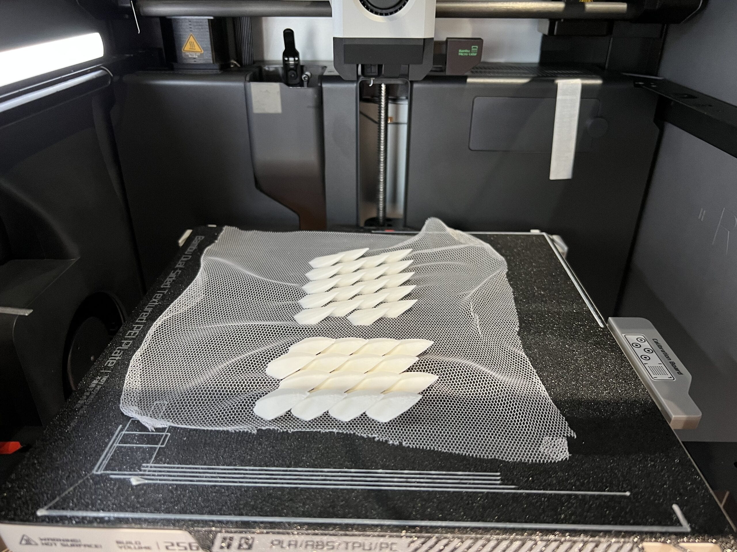
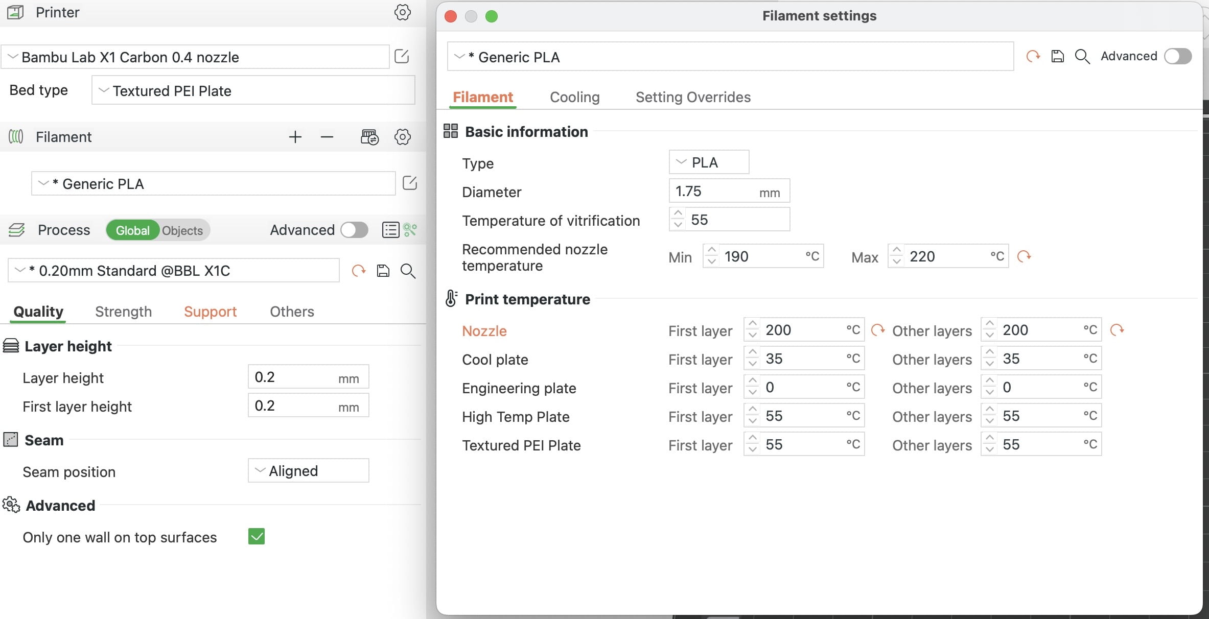
I then started to test with this color PLA and printing fish scales. In such process, there are several findings. First, this material works pretty well with the default Genetic PLA settings. But there are some small defects when using the default setting. As the best temperature for this material is 190-220, while the default setting uses 220 as the working temperature, I guessed that lower the temperature a bit could help. It turns out that when using 200 degrees, such defects are reduced greatly.


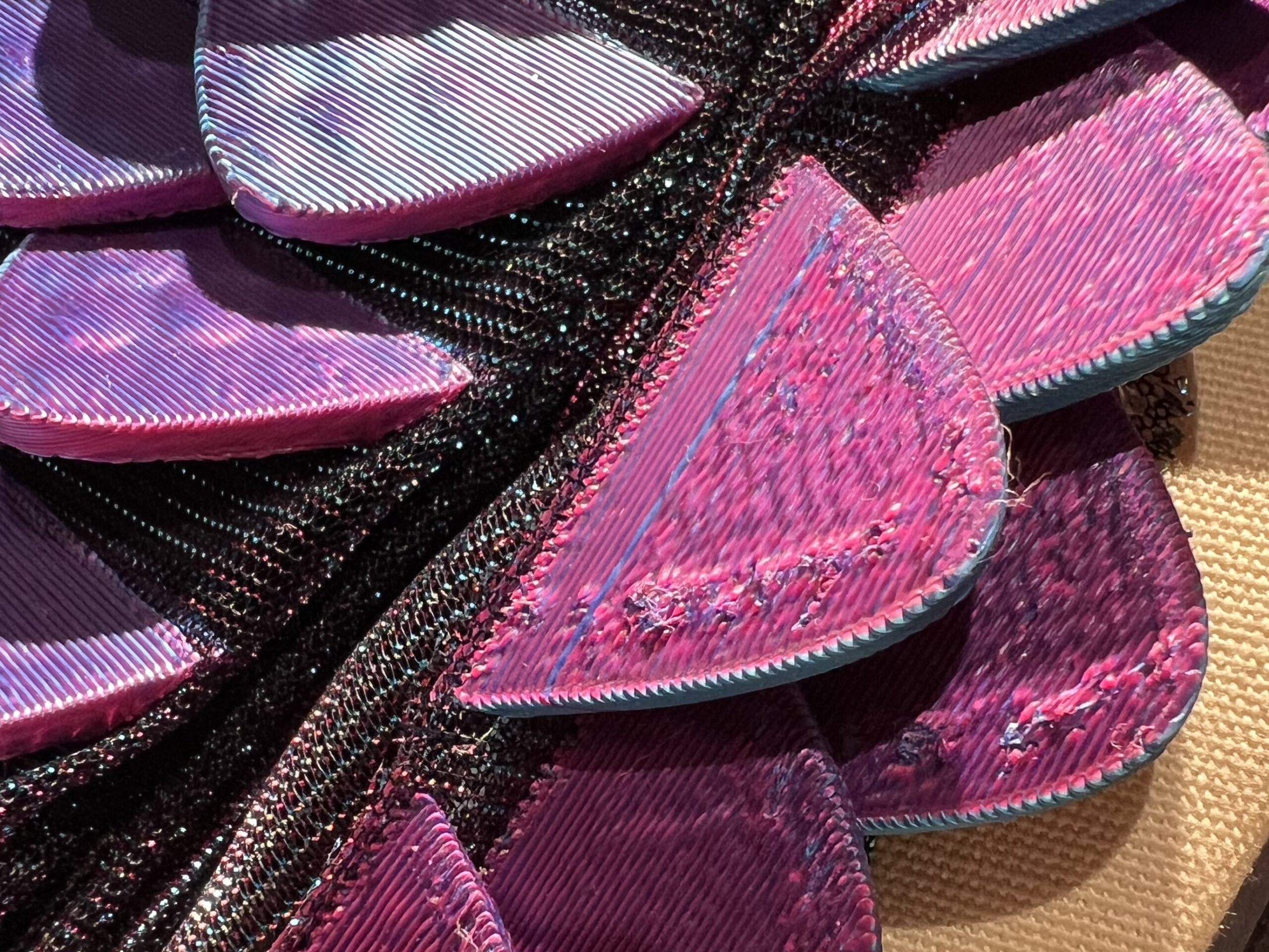
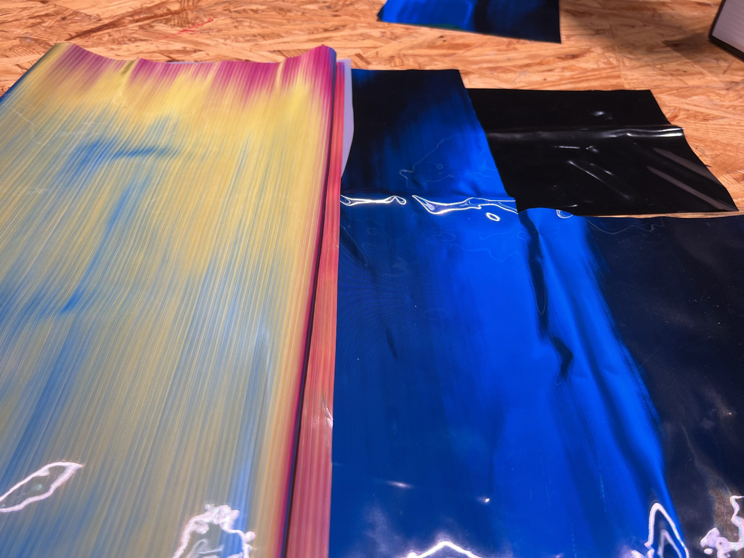
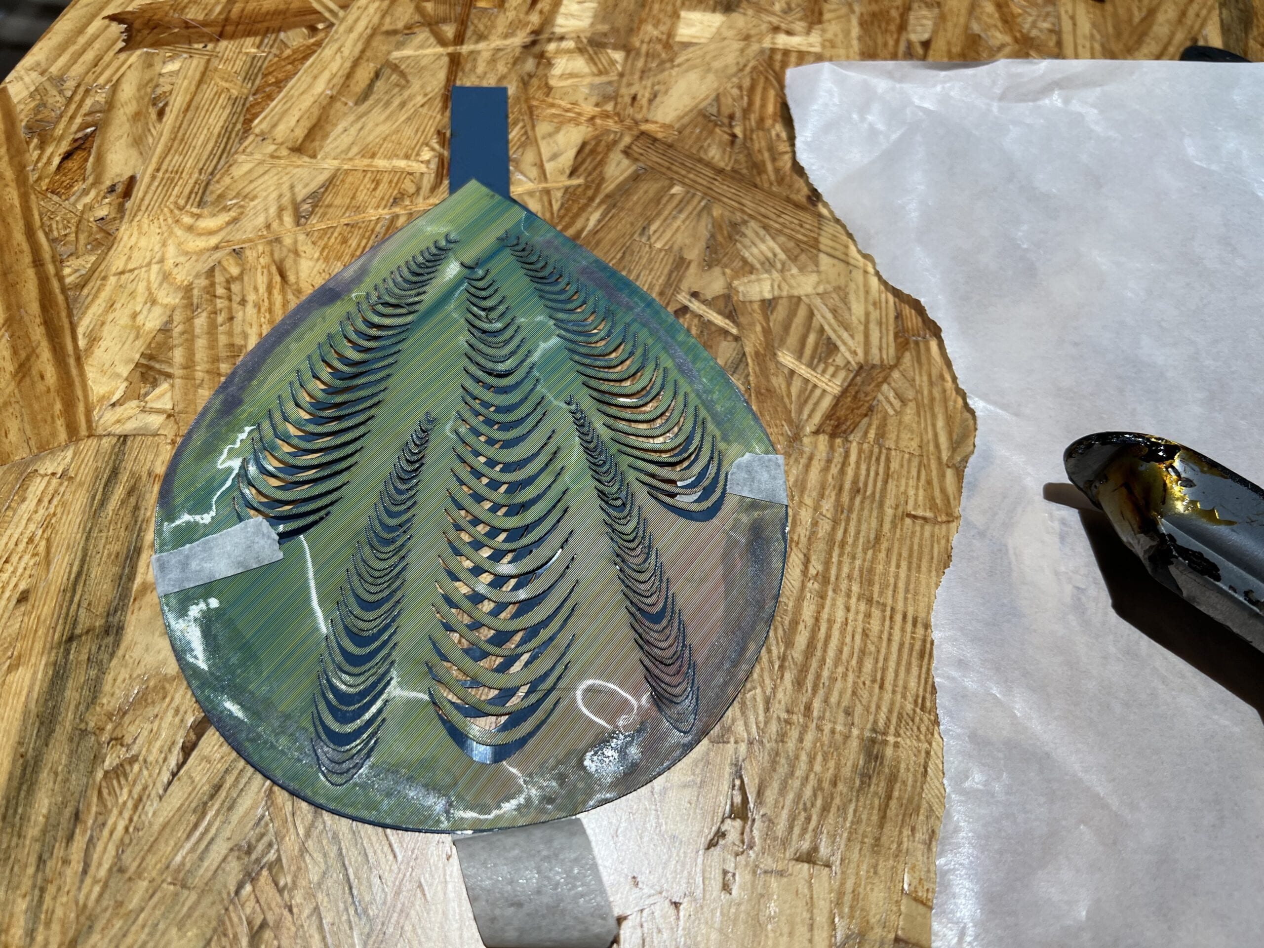
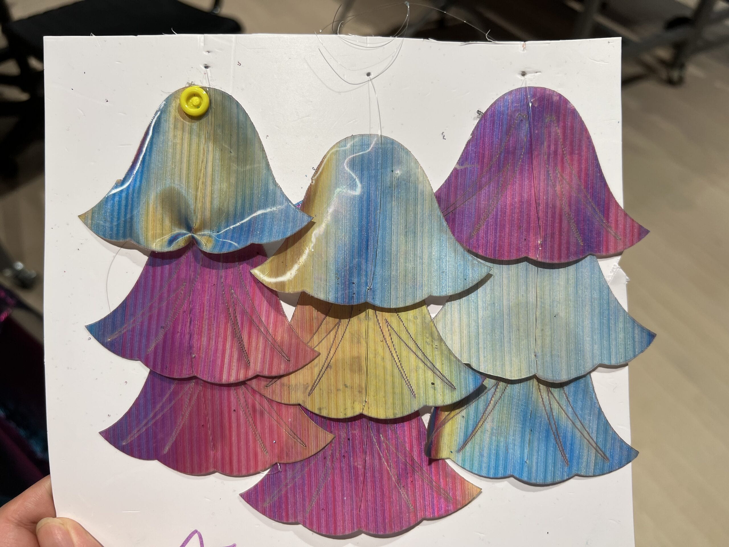
The second finding is that this material makes gradient color by having both red and blue color at the same time, to be specific, it has red color on the front side and blue color on the back side. Therefore, when printing anything with this PLA, the front of the object would be mostly red, the back blue, and the sides would have more pretty combined color (purple). To test its color, I printed scales by placing them differently in the printing machine, when placing scales forward into the machine, the front of scales would be red, and the back side (which cannot easily seen) is blue. However, when I rotate the scales by 90 degrees, it would have the gradient color shown, as such color variants from blue to purple when observing from different angles.


The third finding is that when applying fabric to the printing after first three layers, the step of putting glues onto the fabric is not necessary. Although the glue helps to hold the fabric in place, it is extremely hard to clean up the plate after using, and the fabric would be sticky for a very long time. Instead of applying glues, I found that using paper tapes at the edges of the fabric would also work. The fabric would not move around and mess the printing up.

After trying to produce them in large amount, I found that my scales are too close to each other, so that the base fabric cannot bend and twist freely, which means the scales can not be applied to the dress where bends are required (such as waist area). Therefore, I redesigned the models a bit and started mass production.

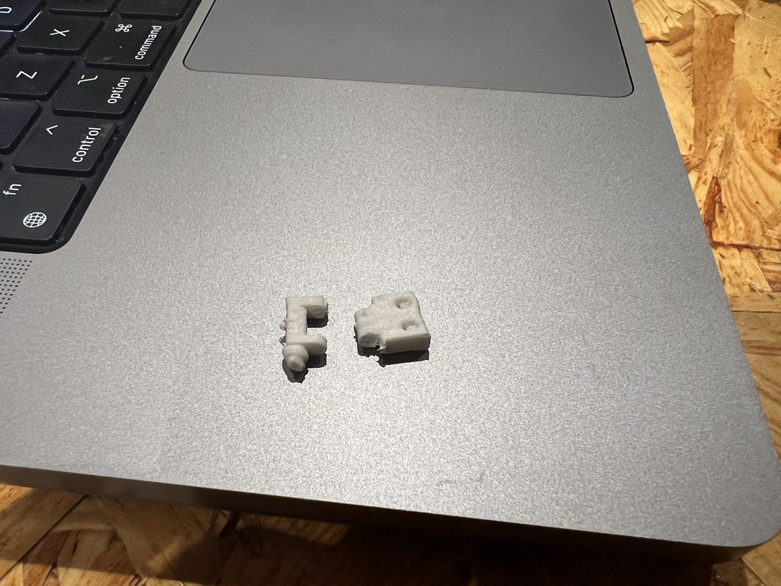
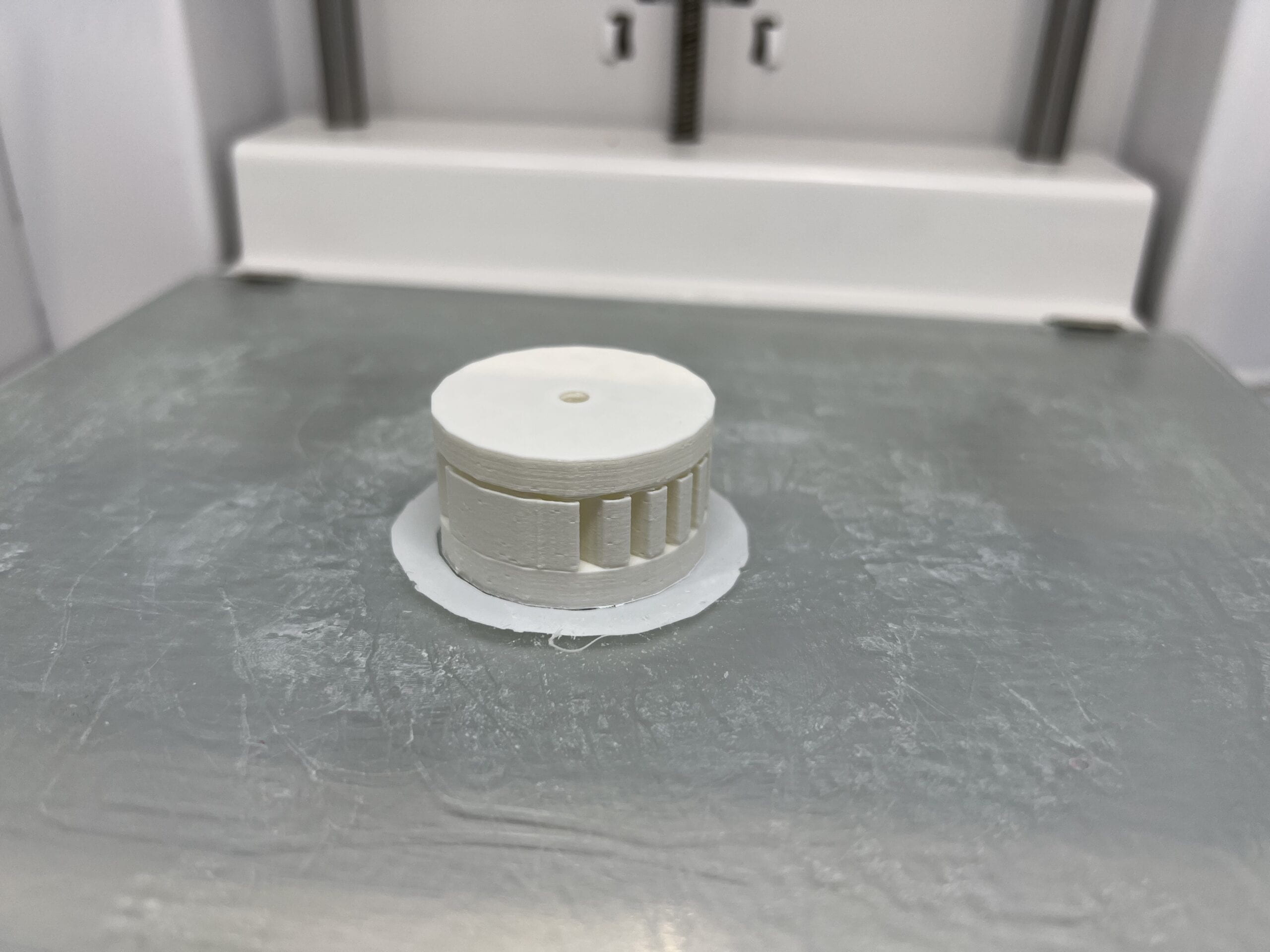
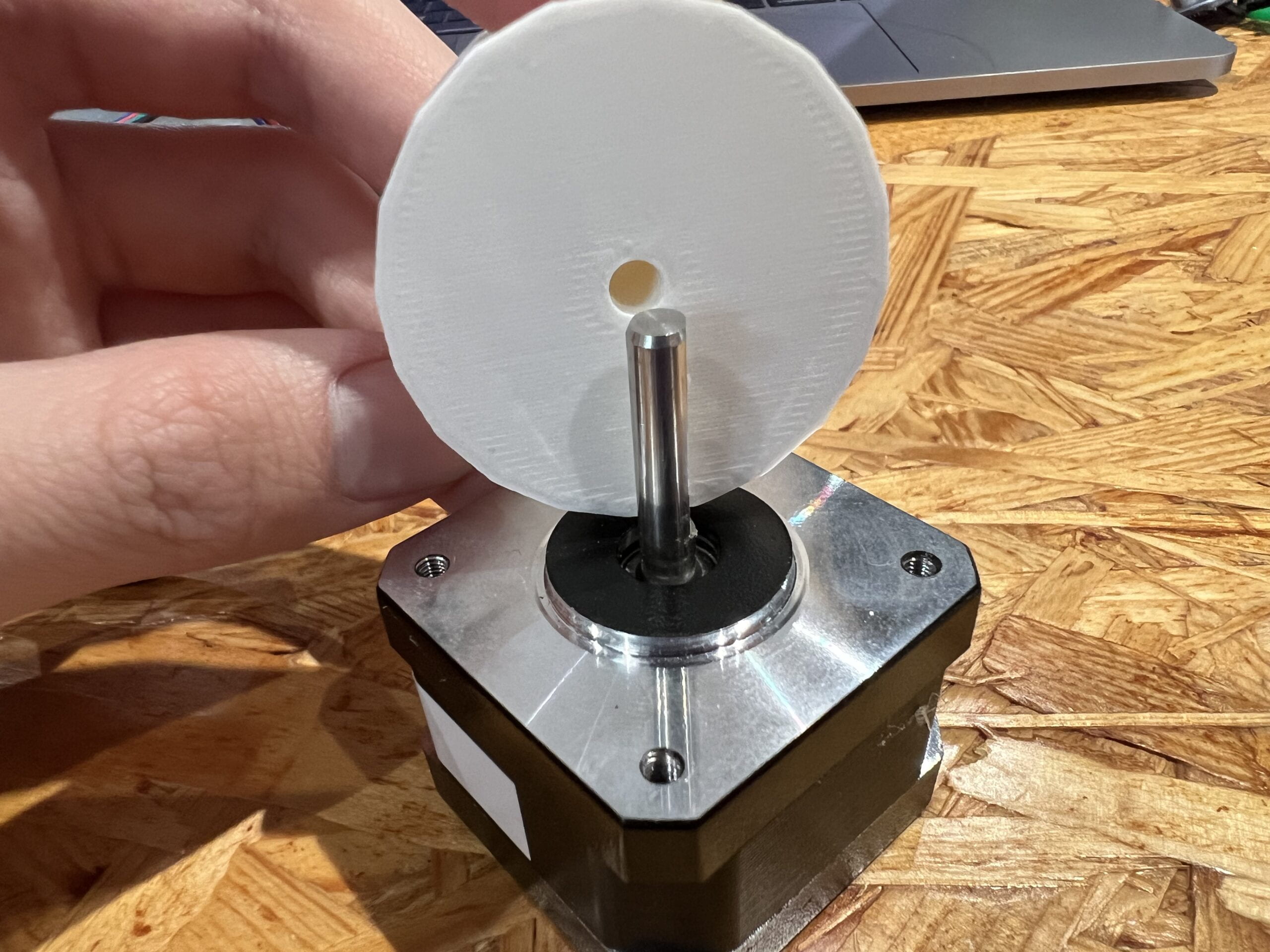
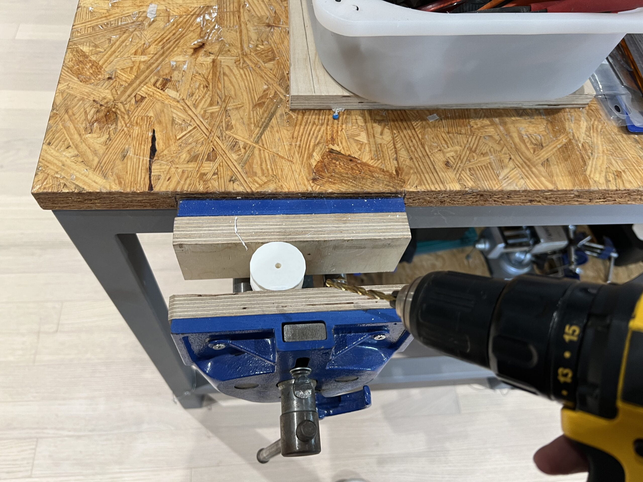
I also used 3D printing to make gears for the motor and a small box to hold the distance sensor (thanks Johnny for the 3D model files). Even though I kind of mastered the 3D printing process during tons of printing jobs, I think that one should still keep an eye on the printing machine the whole time when it is printing (I spent so many hours sitting next to the printing machine), because you never know what would went wrong in the process. And you can easily find the printing failed or paused for different reasons when you leave a while.

Laser Cut

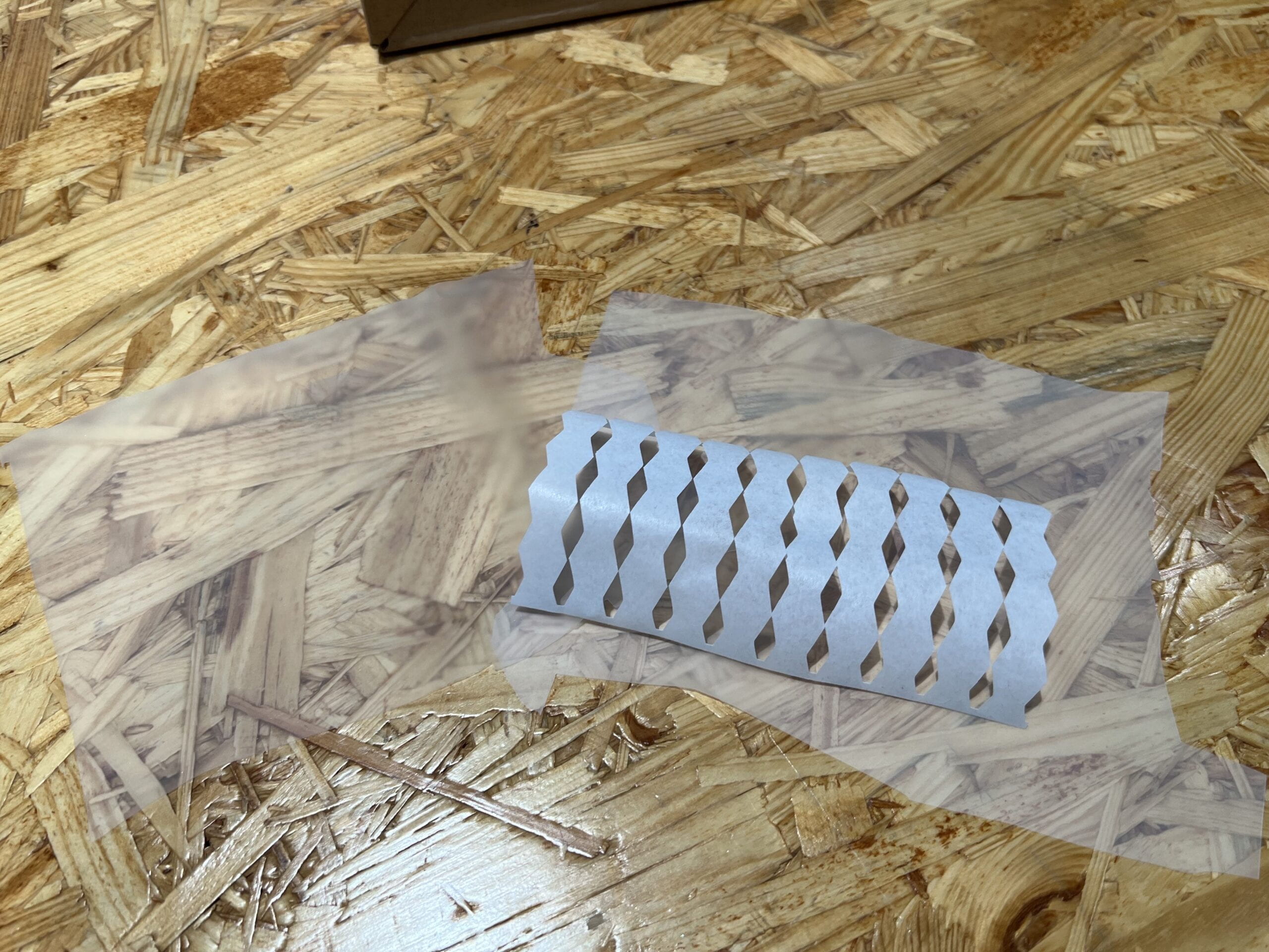
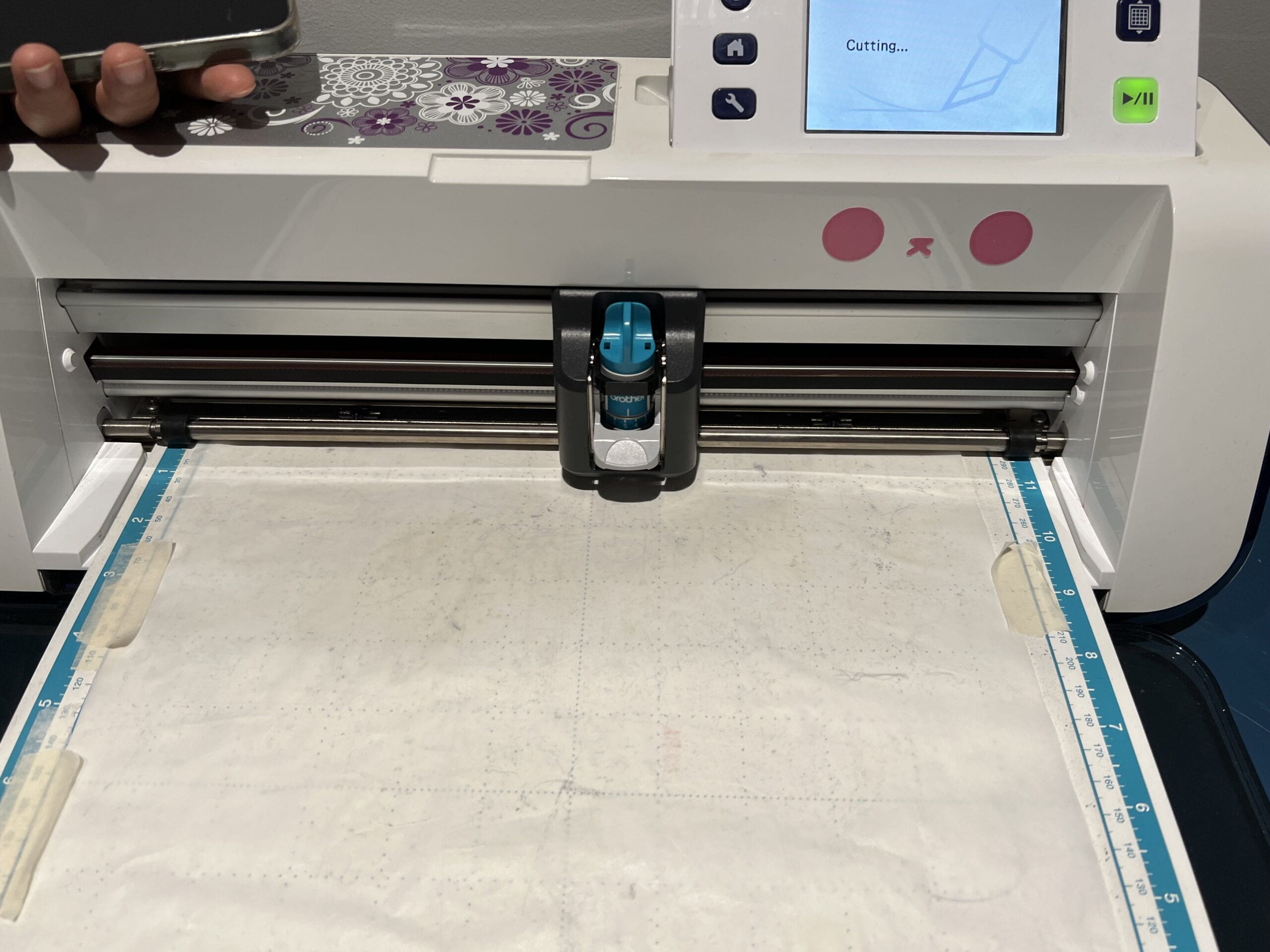
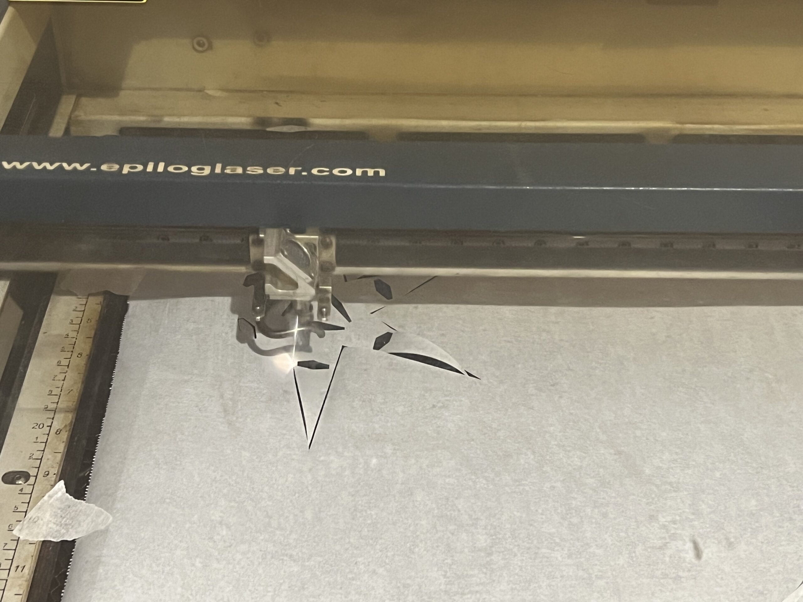
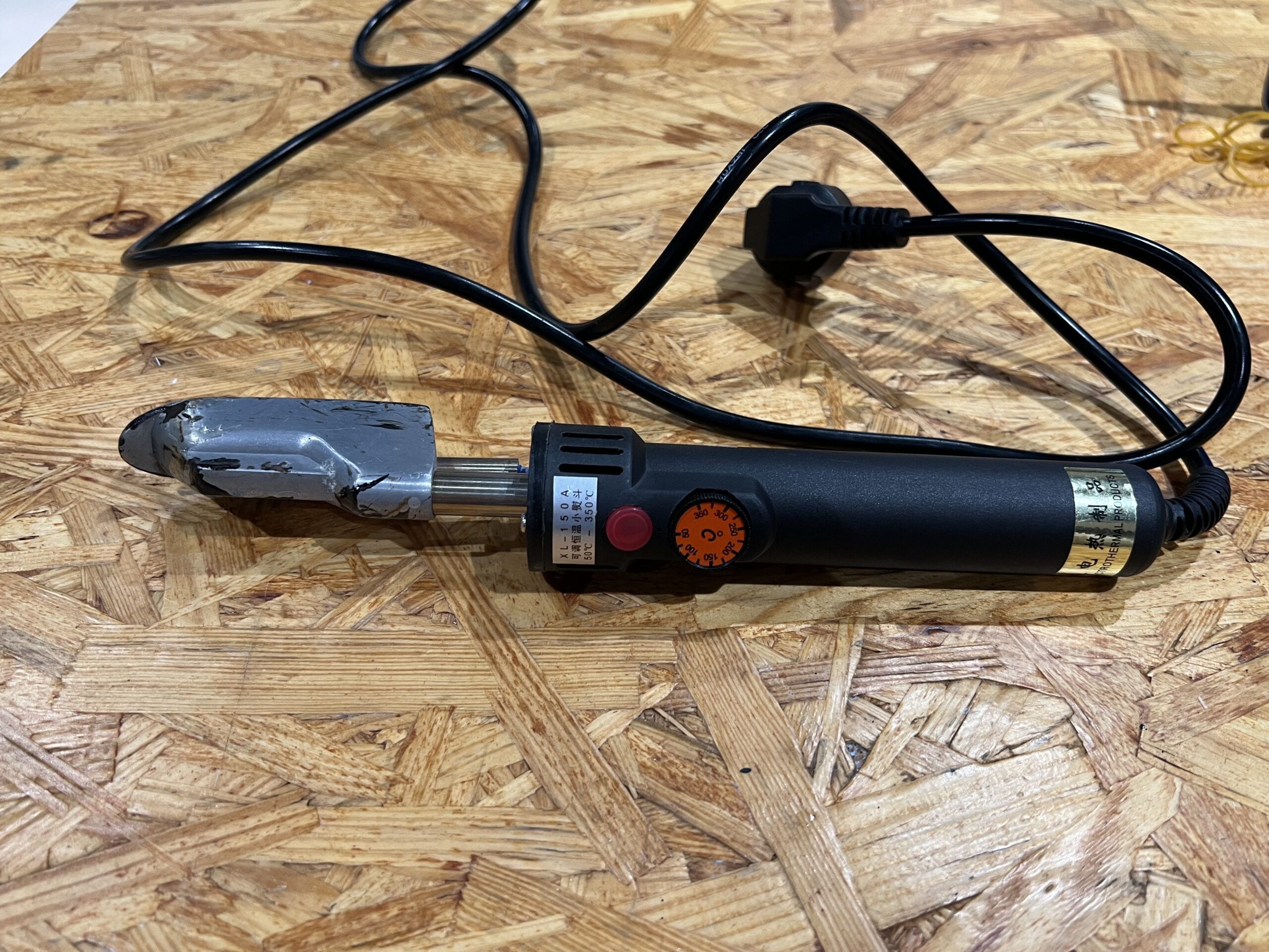
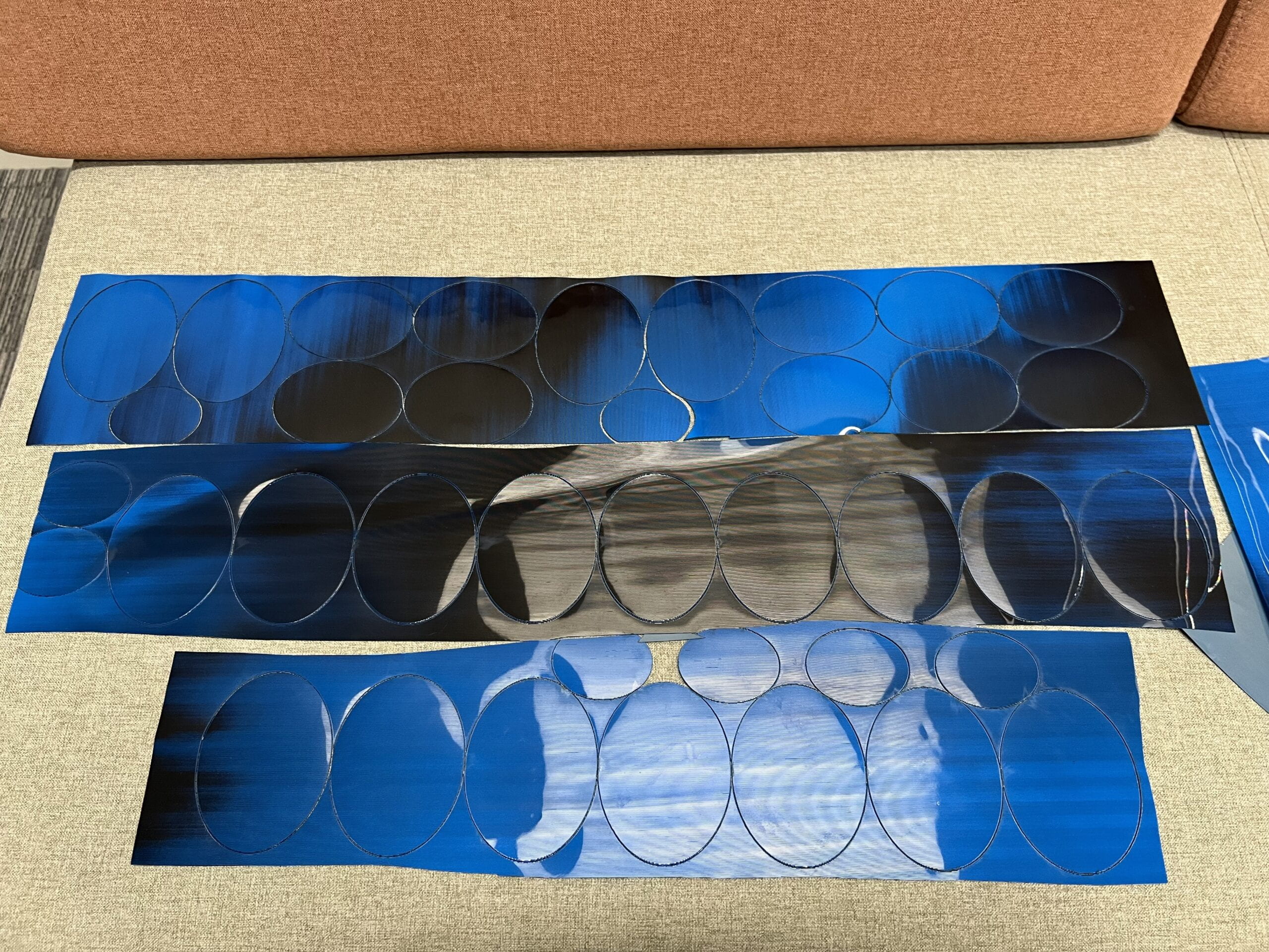
Besides 3D printing, the other tool I used for procuring scales and dress elements is laser cut. Laser cut is overall much easier and less troublesome compared with 3D printing. The main difference from ordinary laser cut was that the material we used are not plywood or acrylic, but TPU, and I have to find out a setting for the laser cut machine to cut though while not burning the TPU.

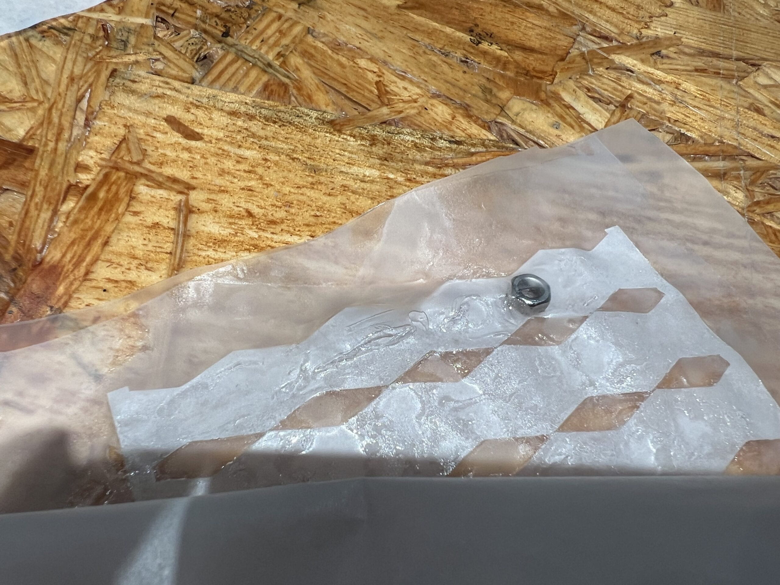
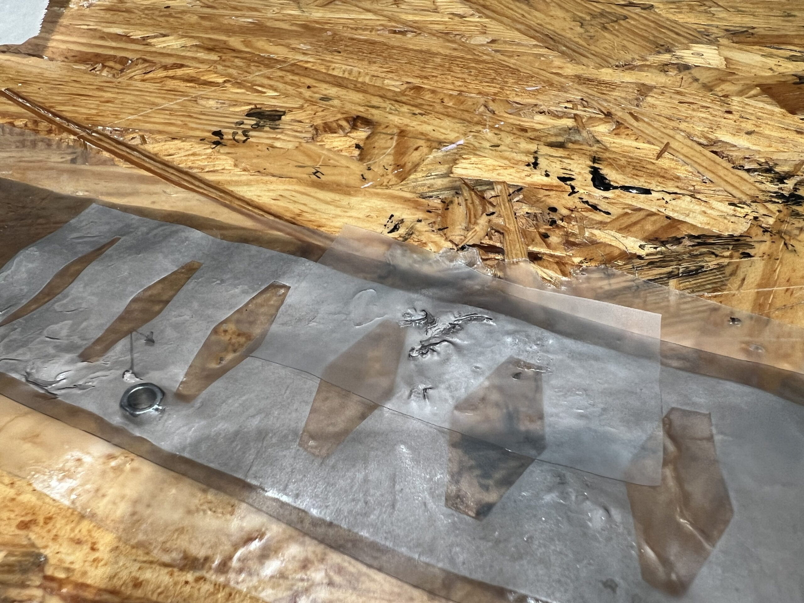
Instructed by Andy, I tested the laser cut by increasing the cutting power little by little. I started with the default settings for white paper, which had 100% speed and 15% power. Then, I increased the power by 5% each time and test with a small circle to see if it cuts though. Not until the ninth try, with 55% power, the TPU was cut though, although still with some subtle connections. I added another 5% power (make it 60%), the TPU was cut in similar ways compared to 55%, where most are cut though, with little connections, however on the back side there is more burning marks compared with 55%. Therefore, I chose white paper setting with power 55%, to cut TPU.

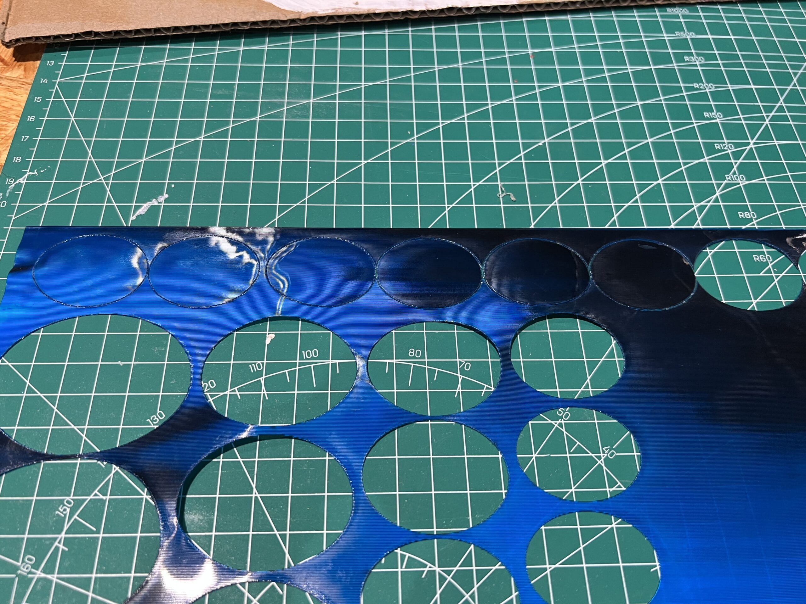
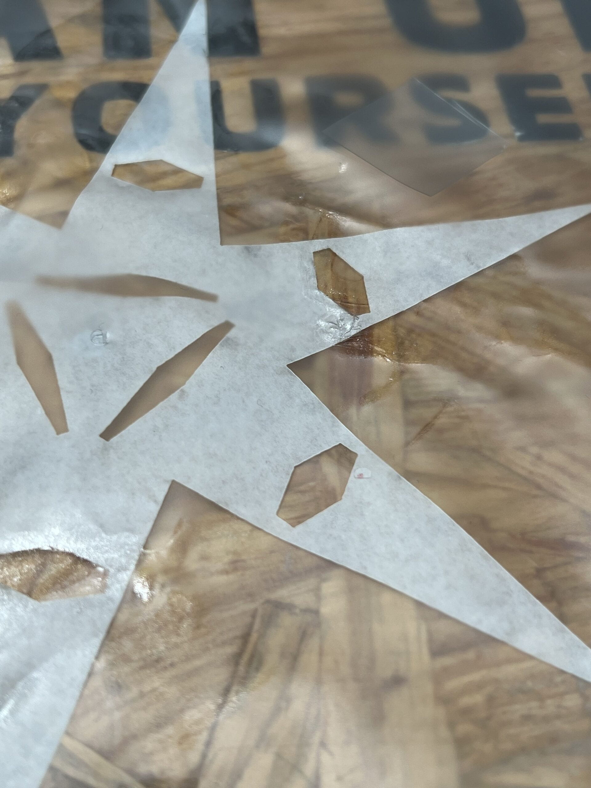
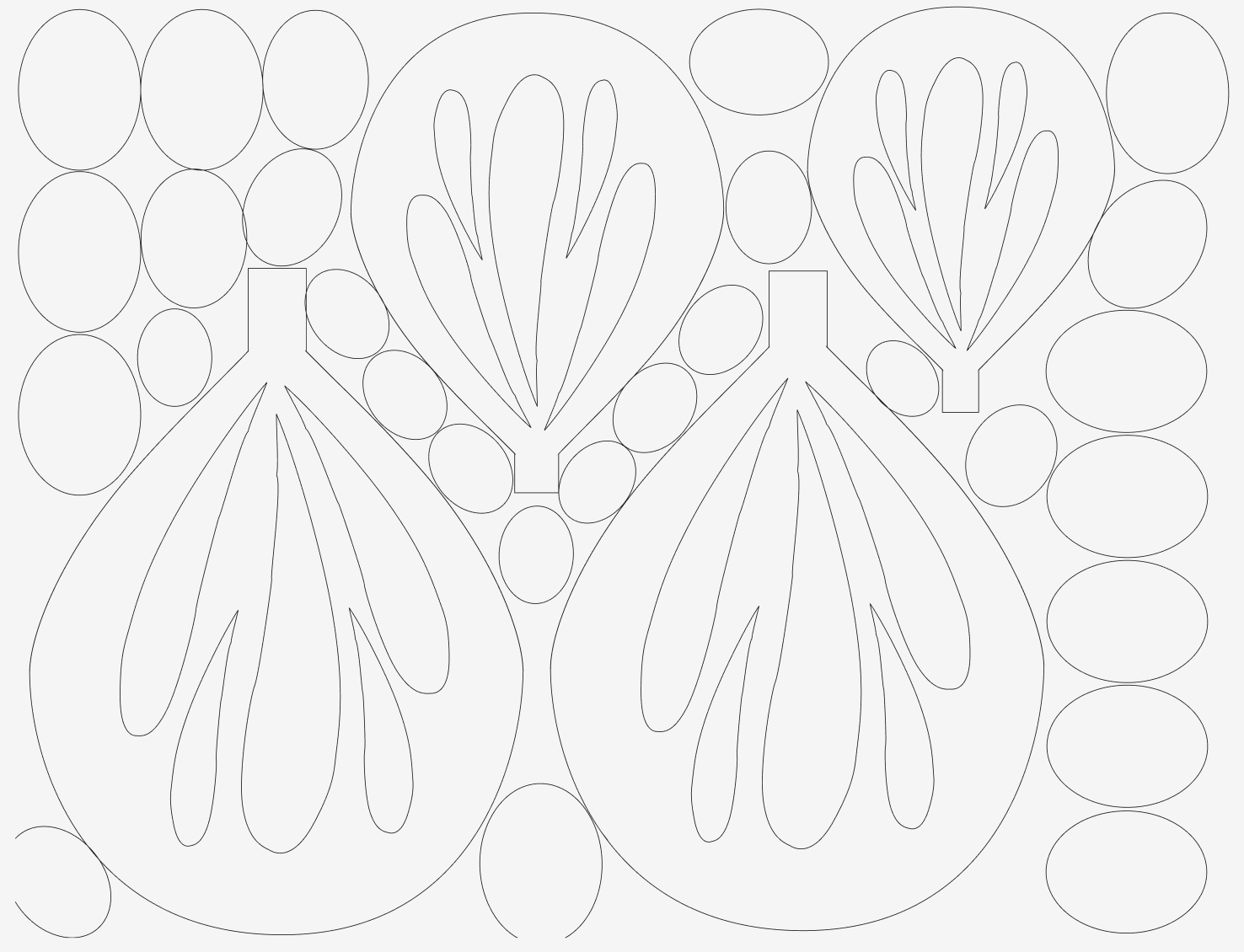
Rainee designed and provided files for scales in different sizes, I then cut them with TPU. The producing process was not difficult (besides that laser cut machine went down for a day), with the only problem that we later found out there might be enough TPU for us to cut all the pieces. So we have to make best use of all materials we have, but carefully design each cut to maximize the space.


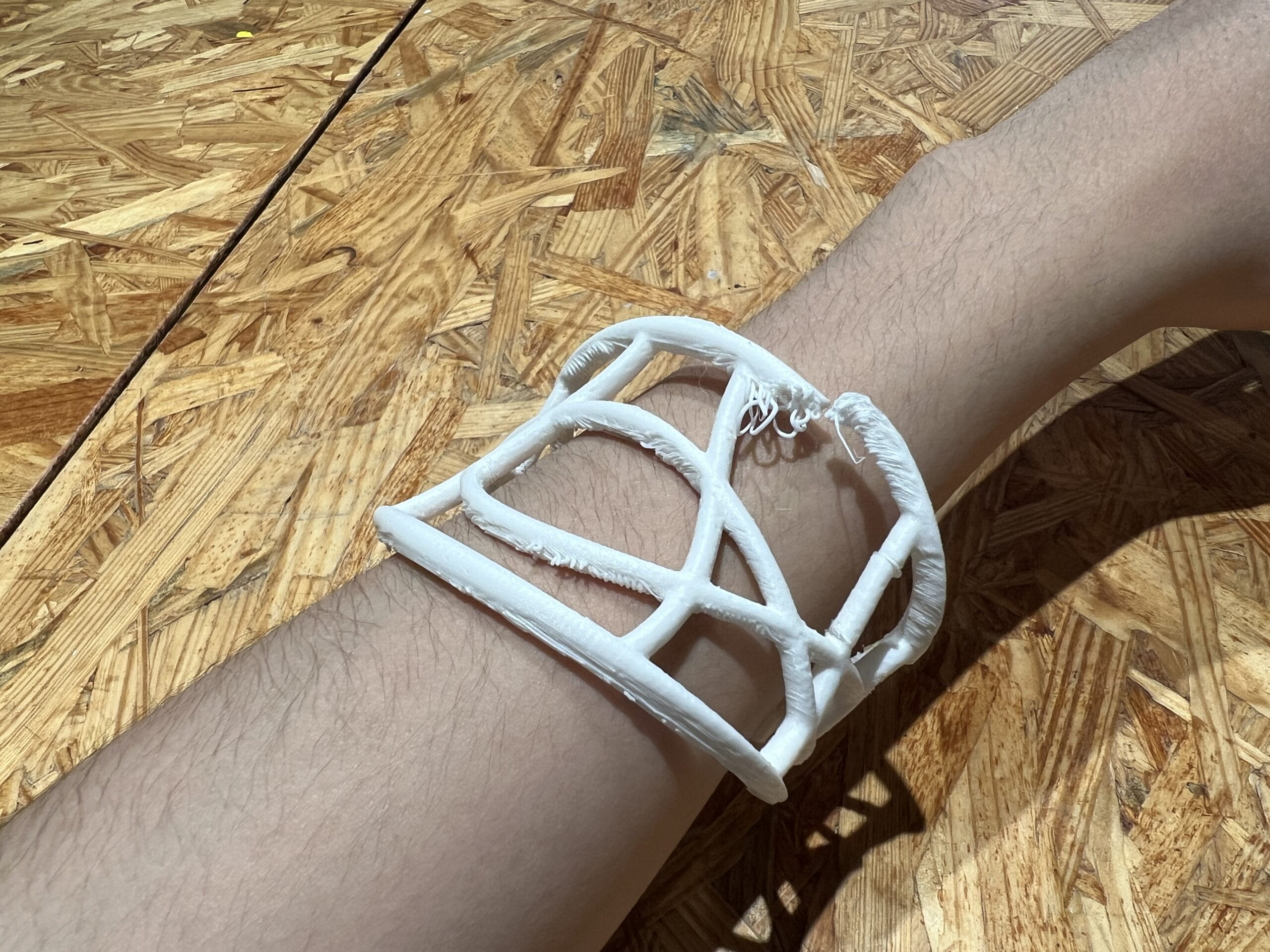
 Besides cutting TPU for scales, Rainee and I also used laser cut for the skeleton part with 3mm acrylic boards, the cutting process was straightforward.

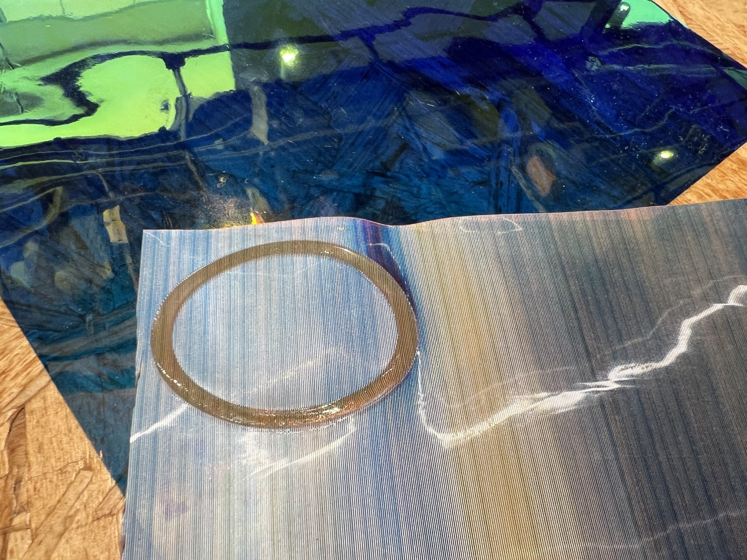
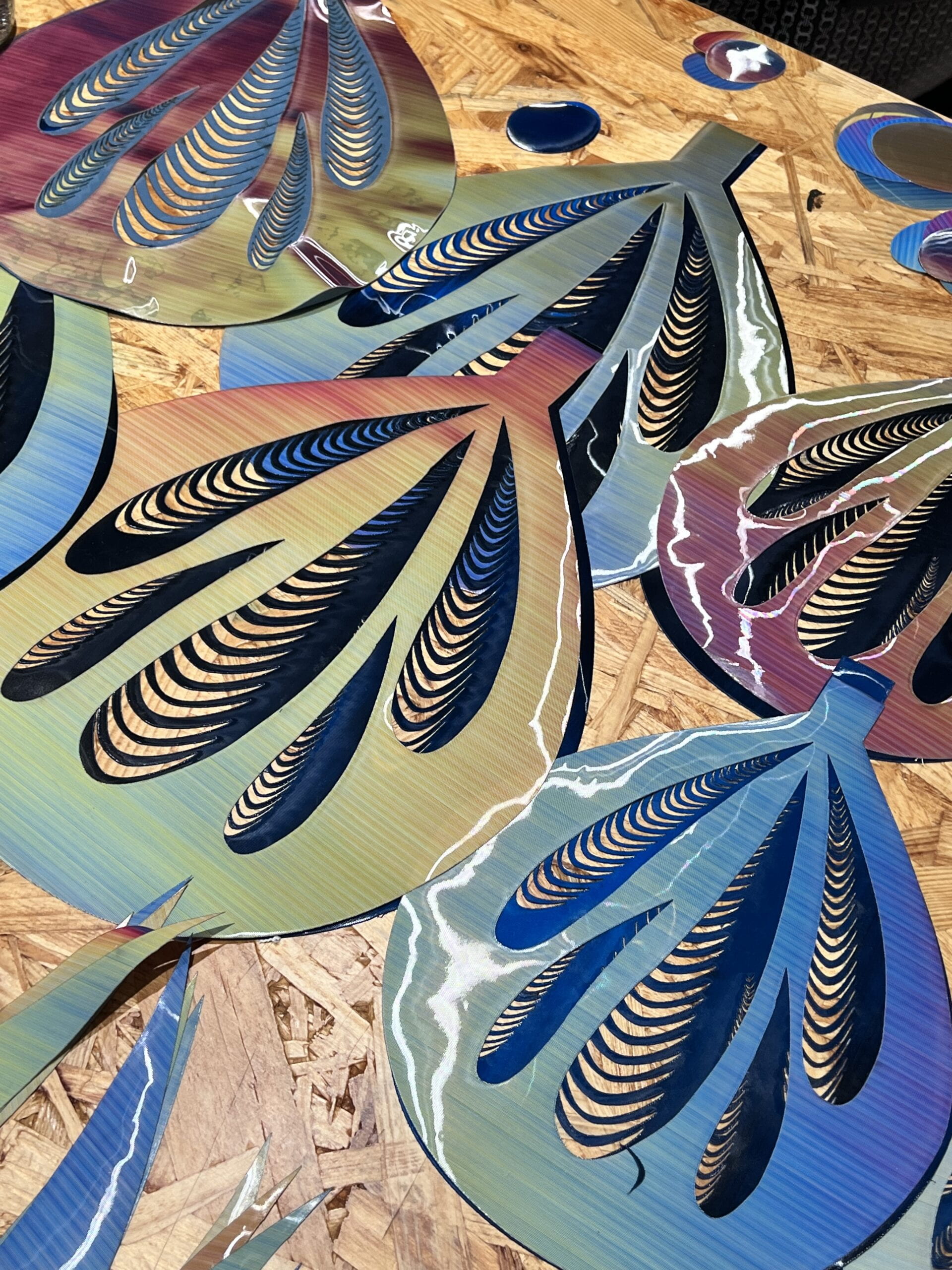
We have also tried to curve patterns onto TPU, to see if we can draw patterns on the scales. However, the laser cut curves do not work so well on TPU, as curving out the front layer only shows grey and yellow color. Therefore, we turned to patterns that cut though the TPU in later designs.

Big Scales & Skeleton

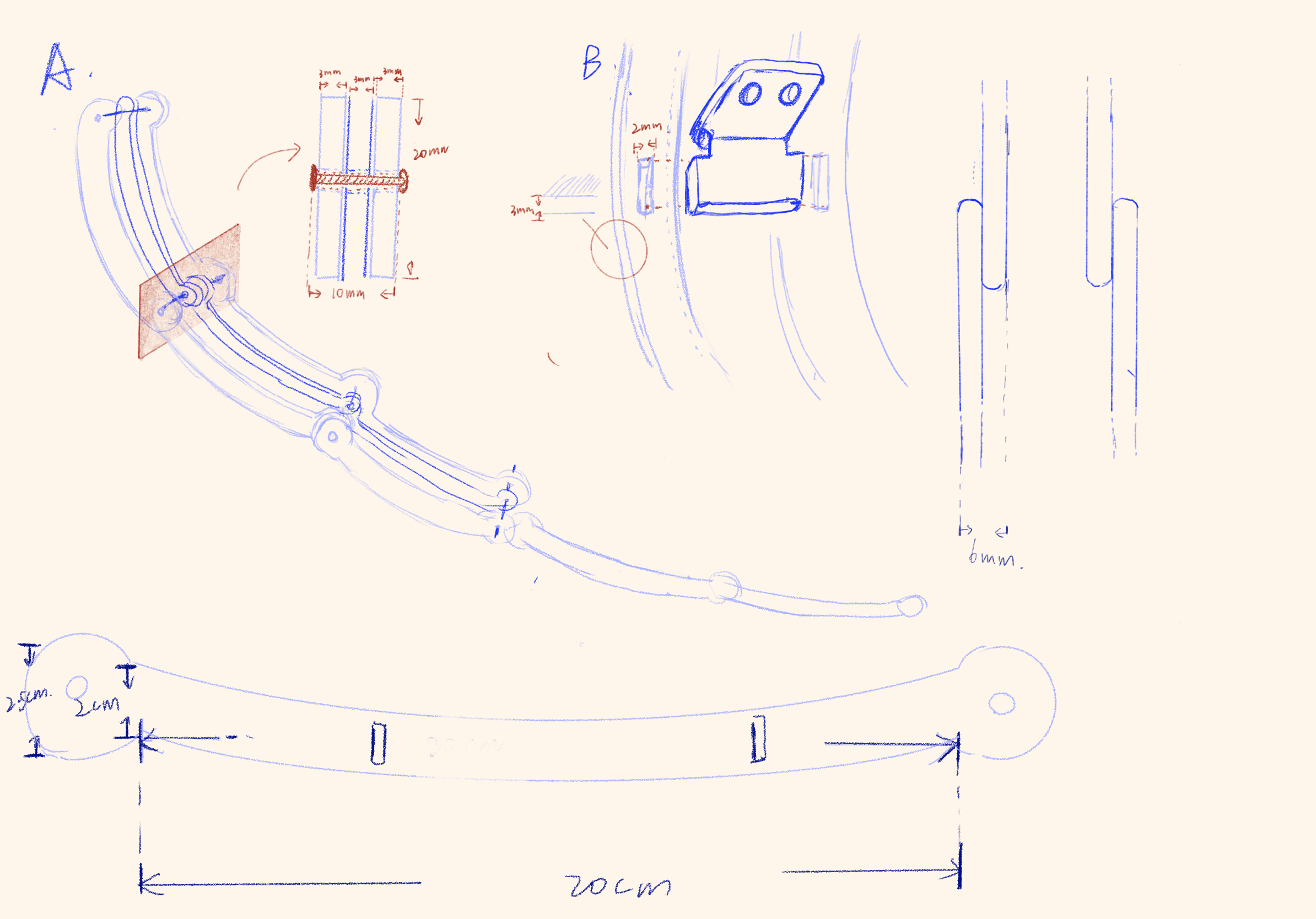
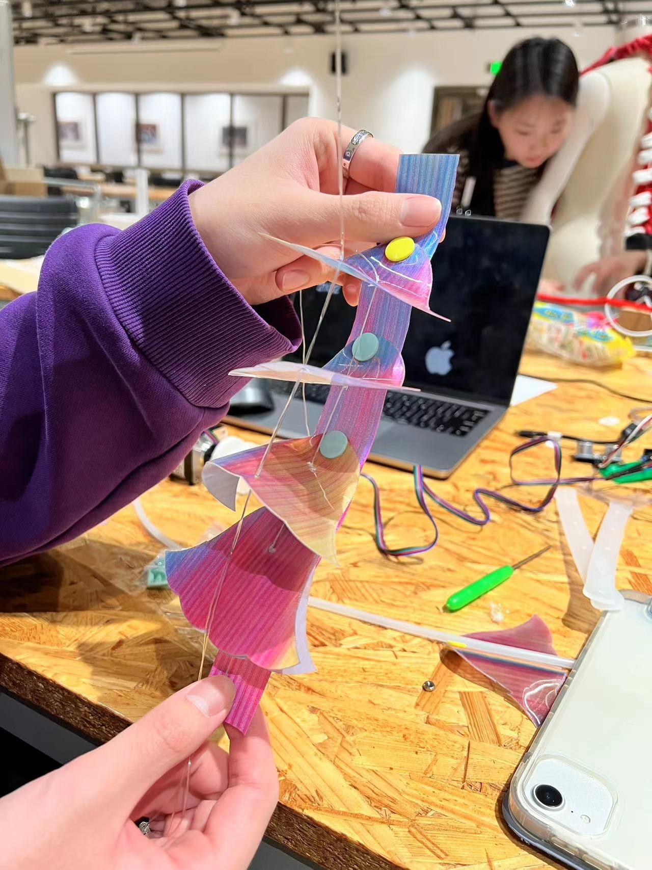
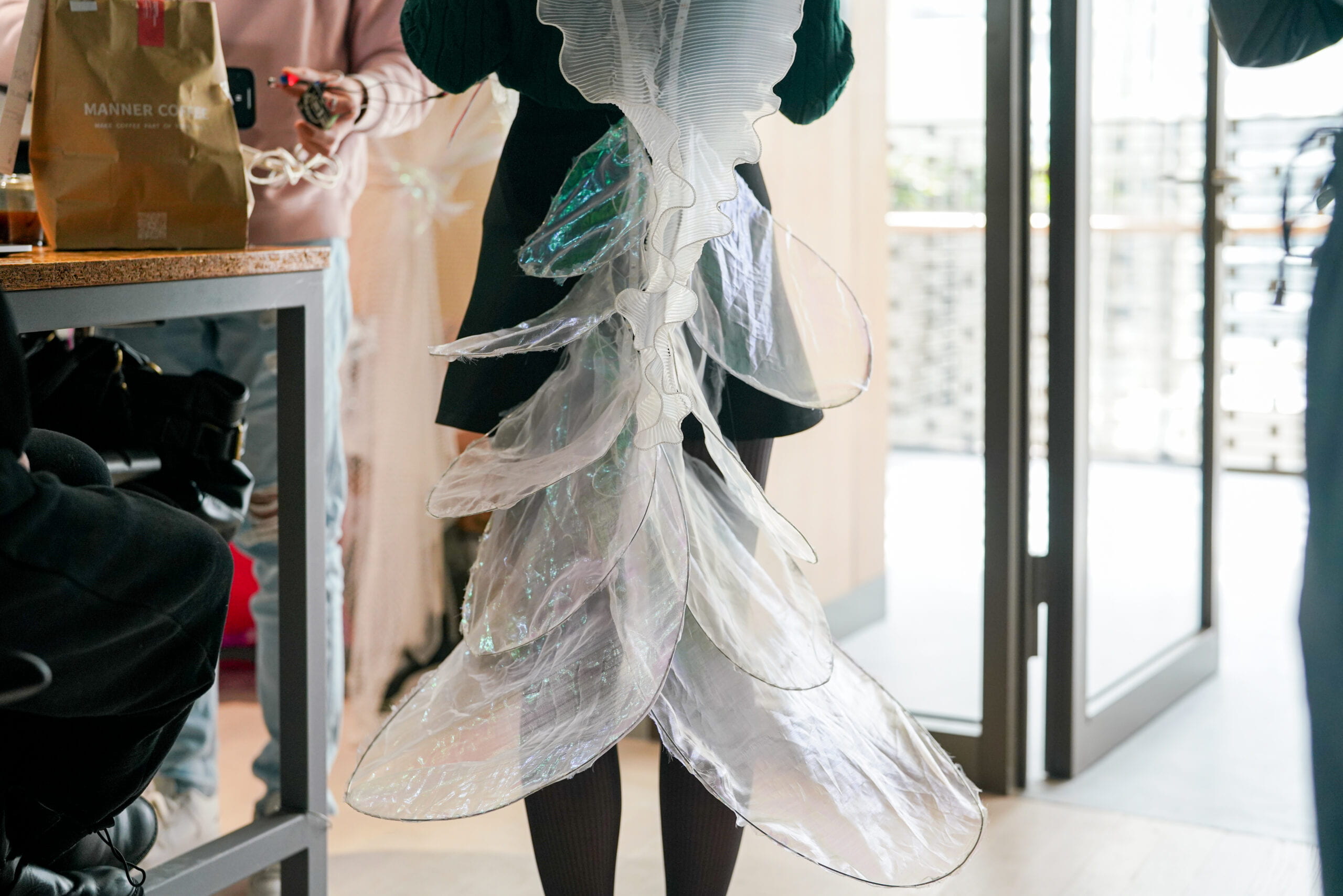
Continued upon the last project, we designed to have some big scales lifted manually, a string connects the big scales and the user’s wrist, so when the user lifts hand and arm, the scales would also move up, along with the skeleton that connects each big scale. Although in the last project we spent quite a long time trying to figure out the best way to join the scales onto the skeleton so that scales could rotate freely, Professor Marcela later inspired us that we can simply leave a strip at the end of the scale and round it over the skeleton. And it turns out that this mechanism worked perfectly.

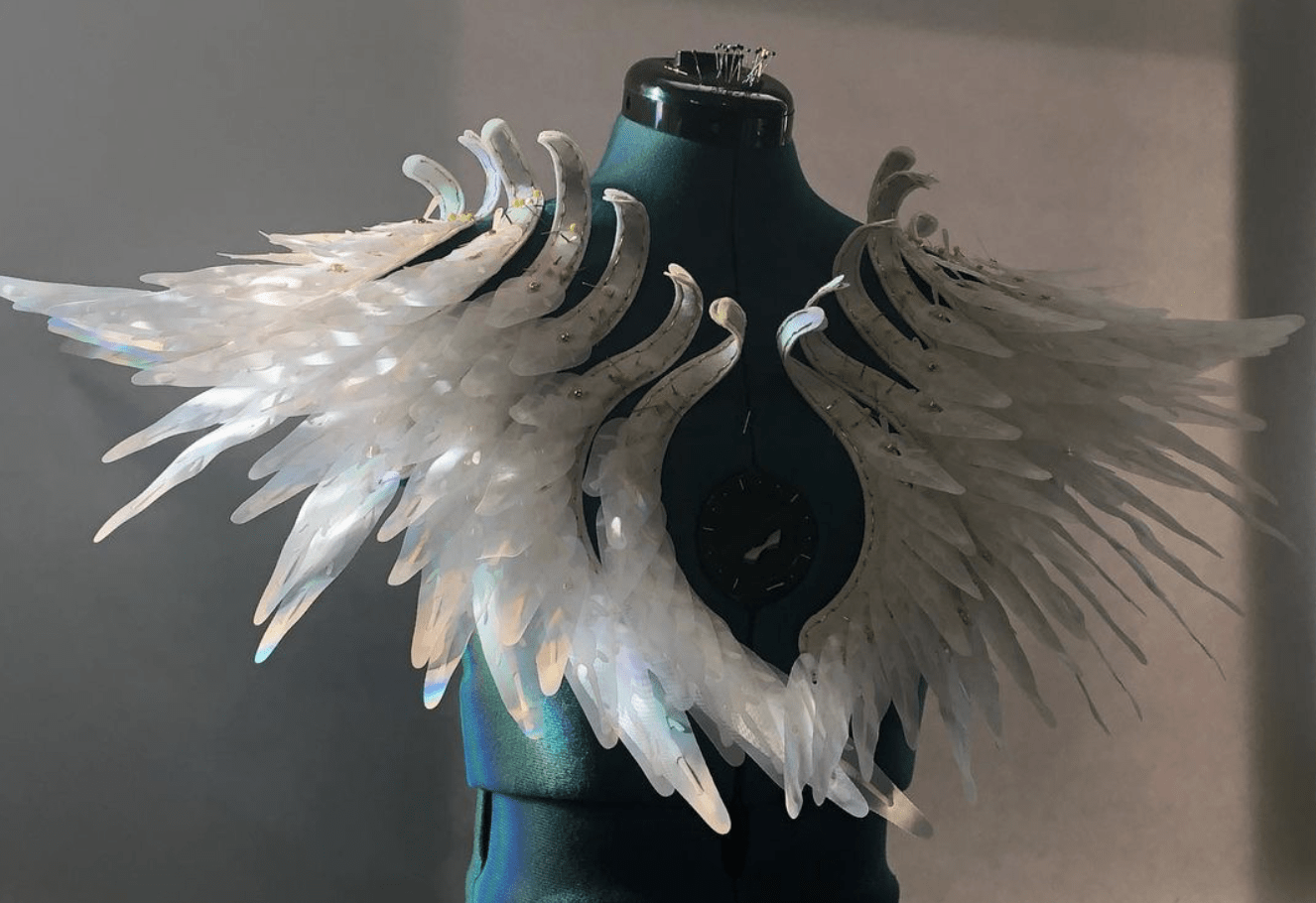
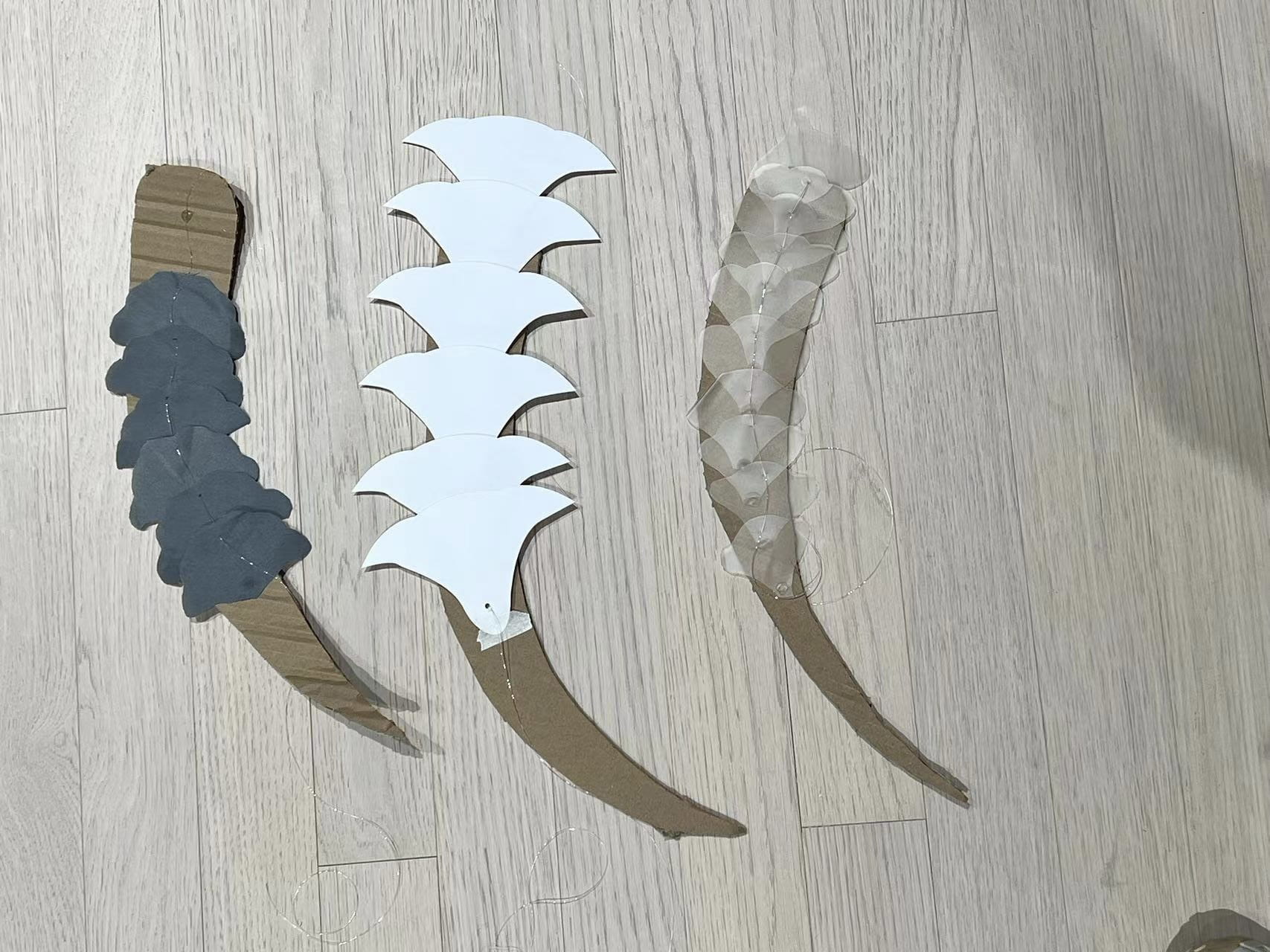
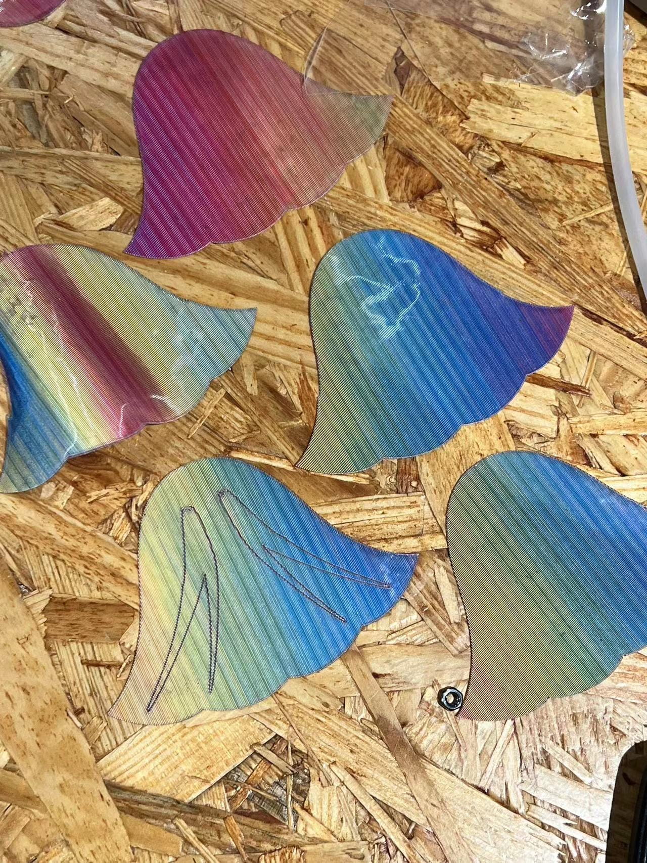
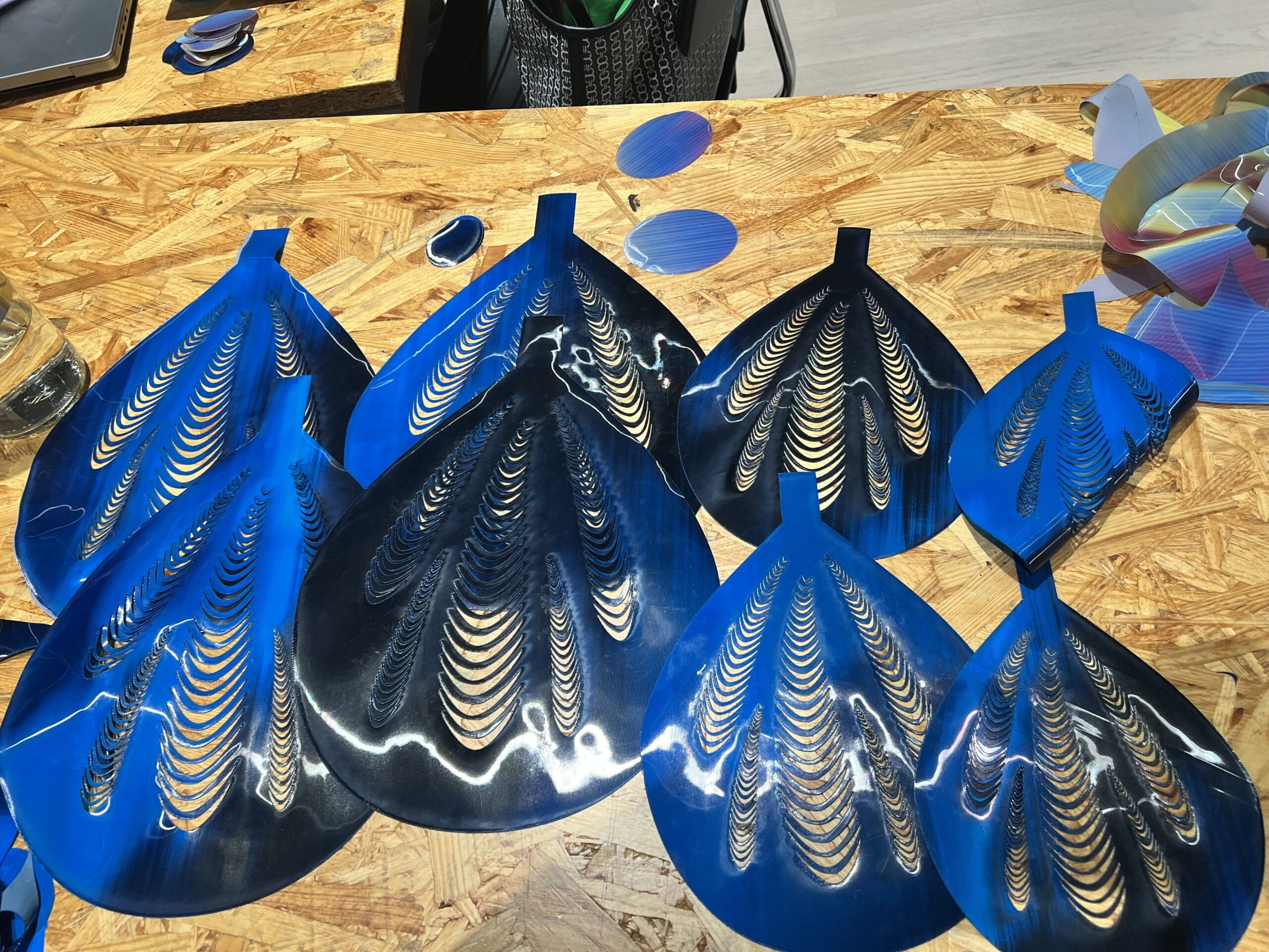
As for the detailed producing process, we found that when the scales are lifted, the back side of the TPU would also be visible to the audience, which are less good liking compared to the colorful front side. Therefore, we decided to make the scale attaching two pieces of TPU together, with the front side of blue and back using the rainbow color TPU. Rainee designed the beautiful pattern for the scales and I laser cut them. The upper scales have smaller size, while them at the bottom are much bigger.


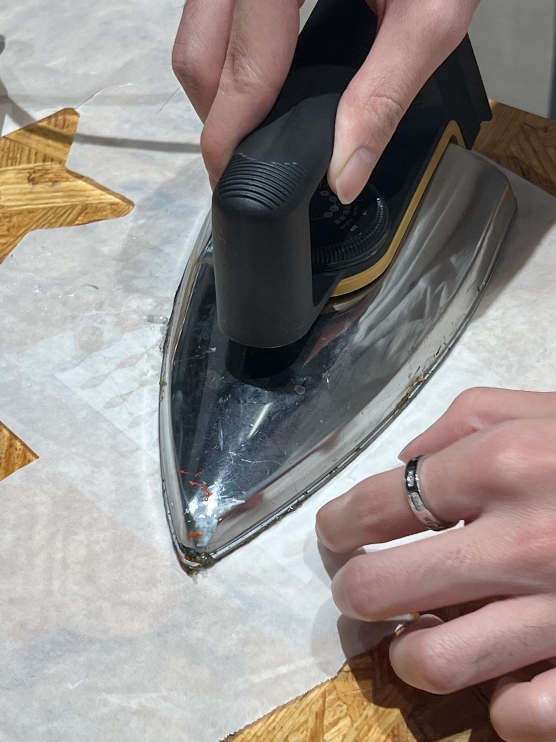
Given that they are made of TPU, we can easily attach the front and back pieces using ironing. However, we found that if merely ironing the two layers of TPU together, the scale would still be too soft. So that when lifting using strings, the scale could not hold its shape and being lifted as a whole, only the part jointed with strings would be lifted, leaving a wired shape of the scale. So we have to make the scales stronger as a flat piece, we decided to put iron wires (thank Johnny for providing the material) along the edge of the scale, right between the two layers of TPU (a hamburger shape), so that the scale would hold itself.

I first iron the edge of two layers of TPU together, then I insert the iron wire into the middle. Since the edges are sealed, I do not need to glue or attach the iron wire, it would automatically place itself along the edge of the scales.


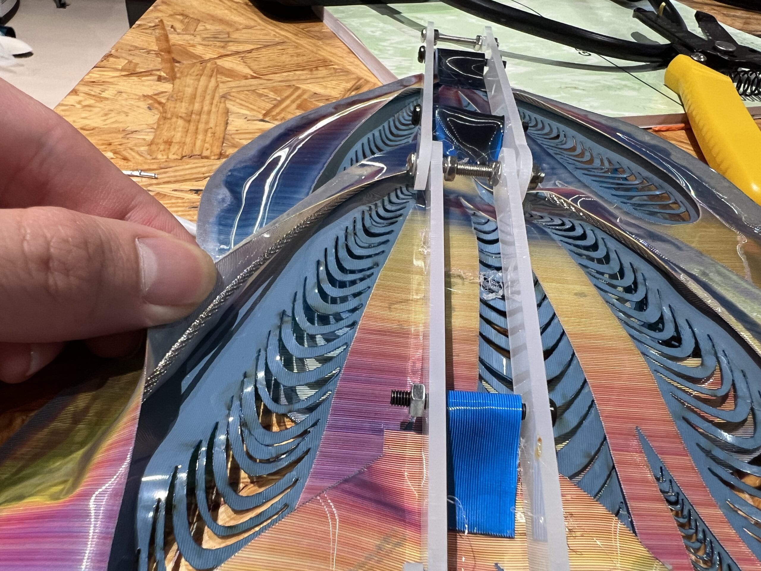
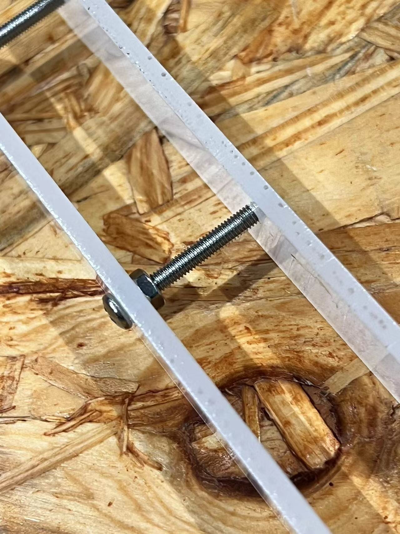
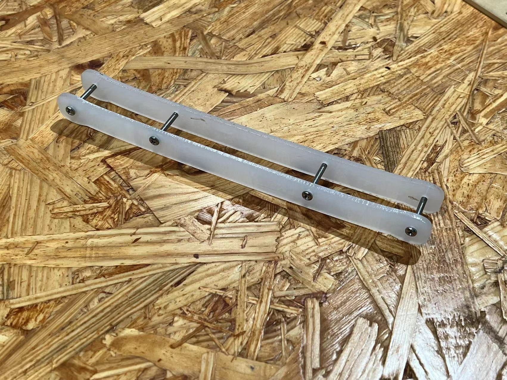
As for the skeleton, we did not make huge changes compared to the kinetic prototype, we shorten each pieces of them and make them less wide, joint three pieces of laser cut acrylic “bones” together as the skeleton for one side. Nails are used to connect them together. Then, I circled the triangle tail of scales around the nails to attach scales onto skeletons.

Rainee and Yasmin later used fishing rods to make the string mechanism and sewed the whole thing onto the dress.


Small Scales & Mechanism

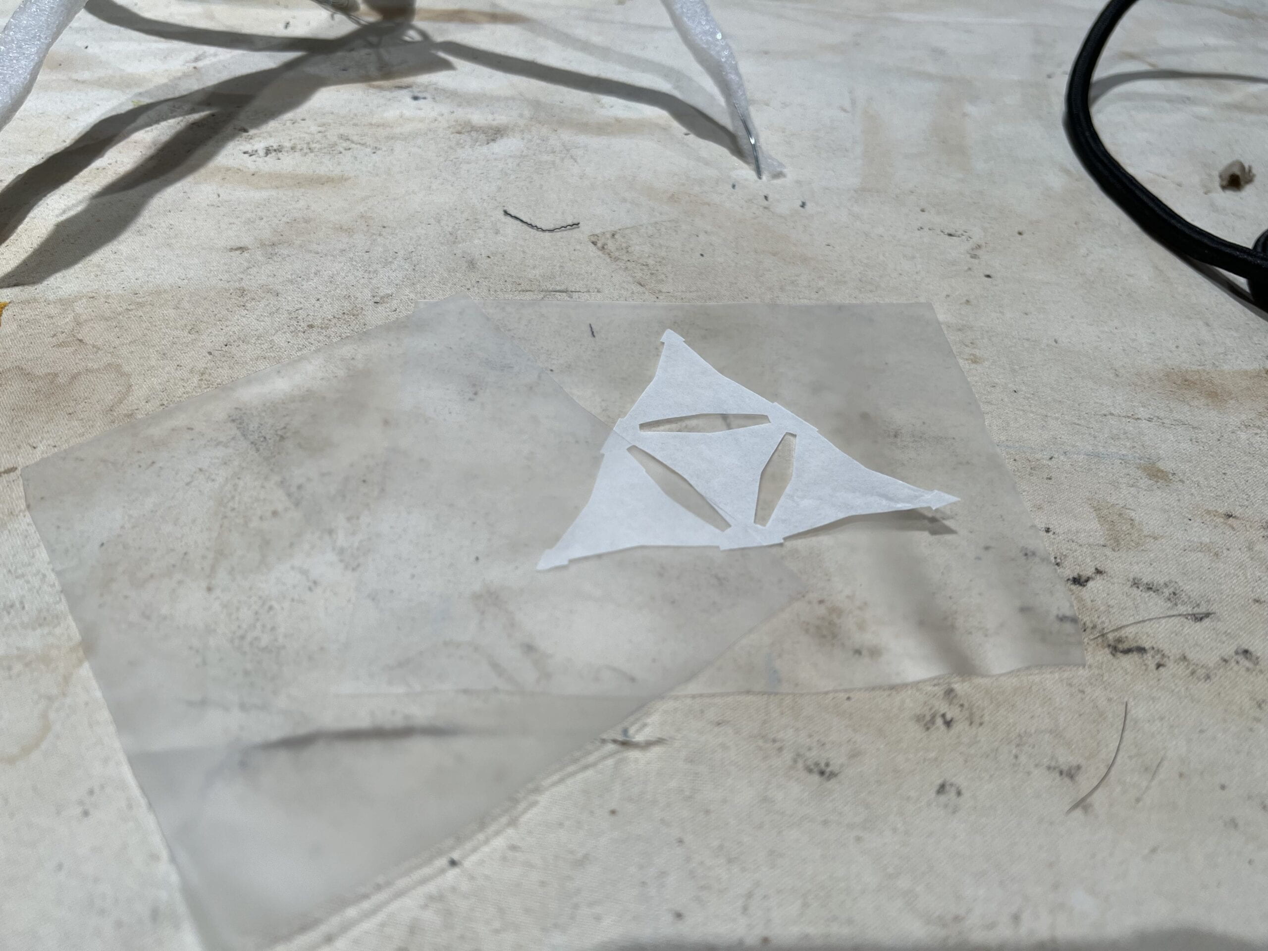
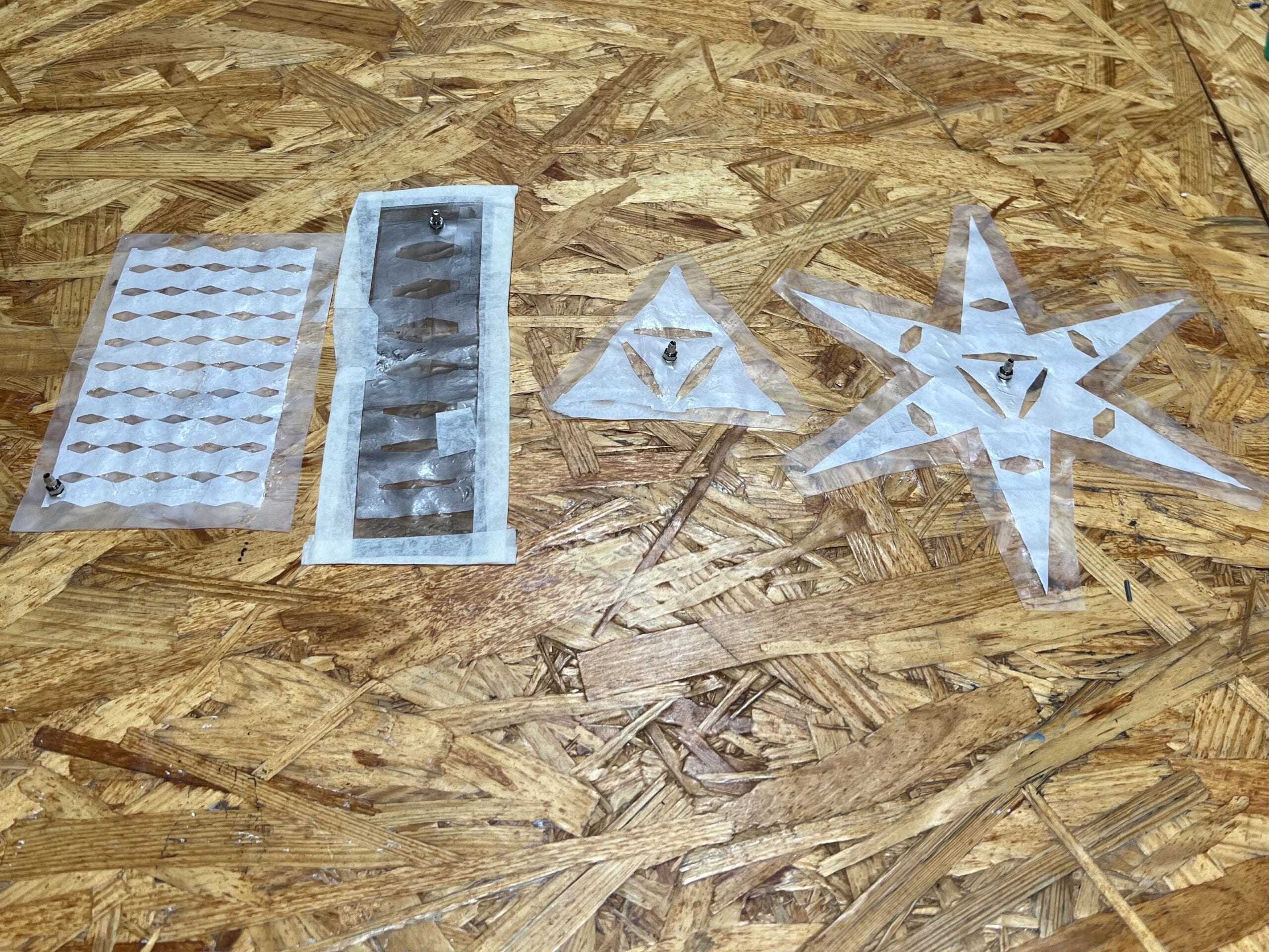
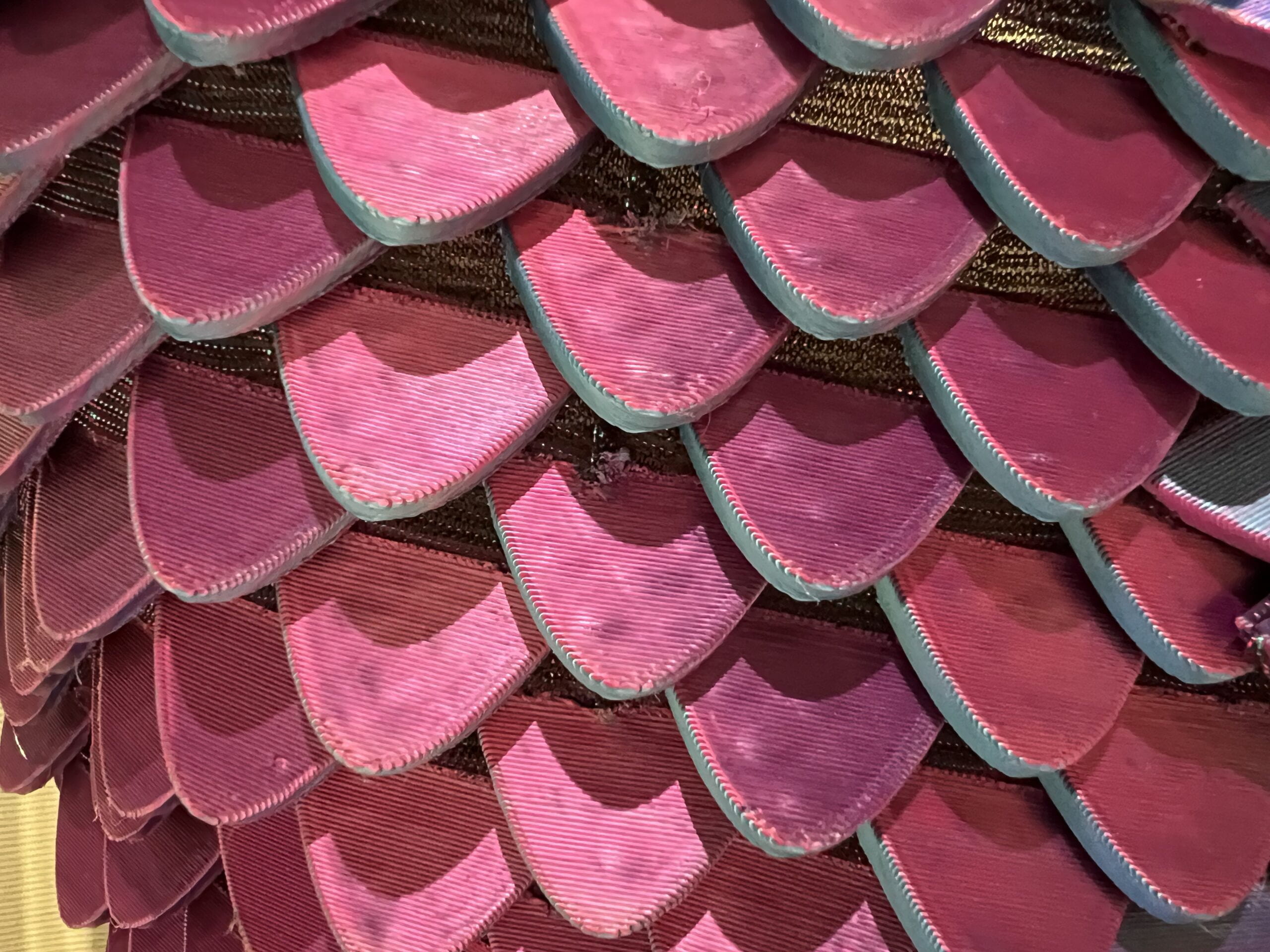
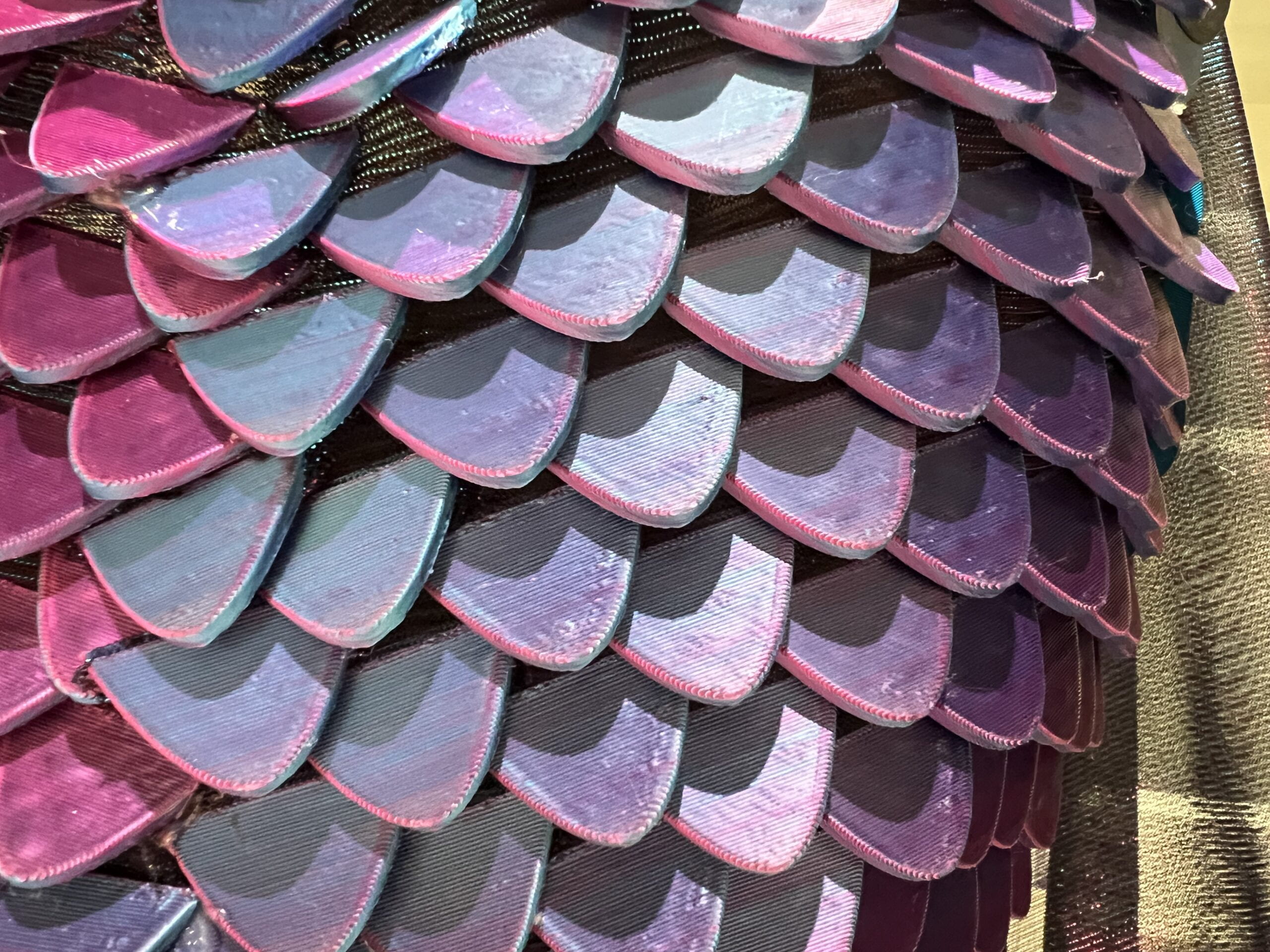
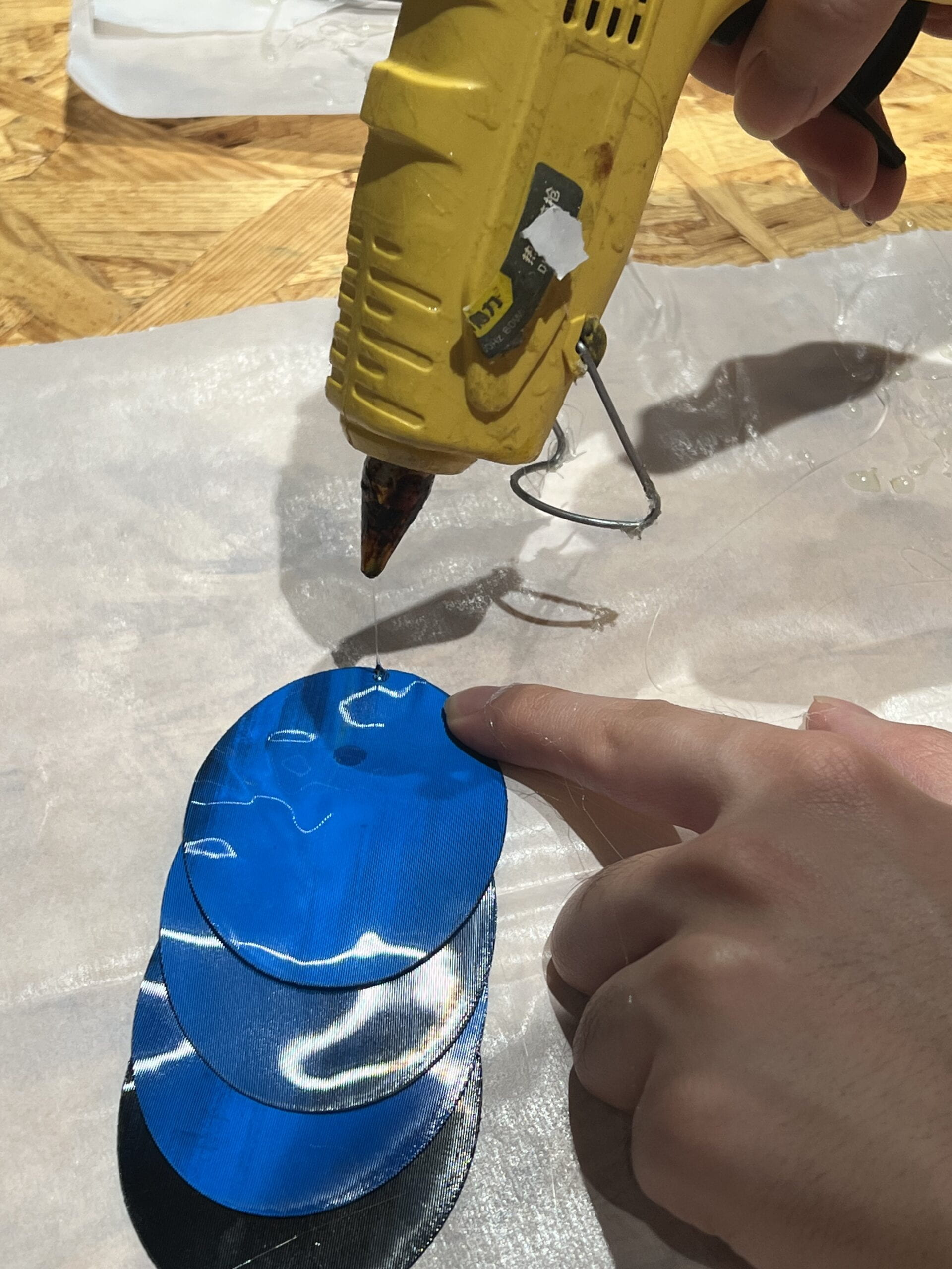
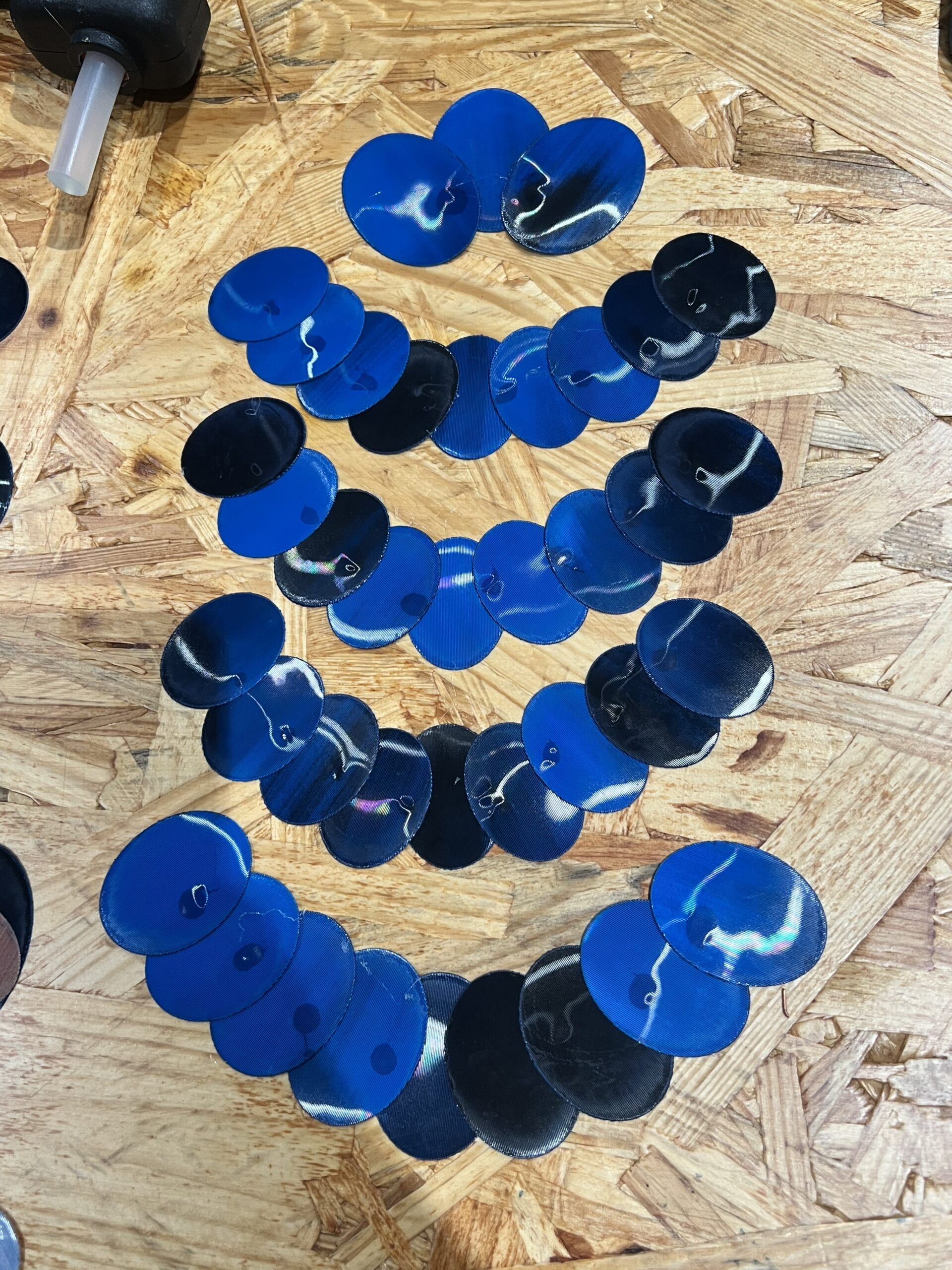
As for the small scales, we abandoned the previous shapes designed in the kinetic prototype, as it does not really reminds people of fish scales, we instead used simple ellipse shapes and overlap them together.


Rainee designed and drew ellipse in different sizes and I laser cut them out. Then, Rainee designed patterns to overlap and place scales together. As for the attachment of scales, we first tried to use iron, since they are all TPU. However, we found the ironing process too time-consuming and are not that precise (since we cannot control exactly the place of attachment). Therefore, we turned to glue guns later, which is efficient and accurate.


As for the mechanism of small scales, we continued upon our last project, the kinetic prototype, to lift scales with strings, which are pulled by motors. We made several changes compared to the kinetic prototype.

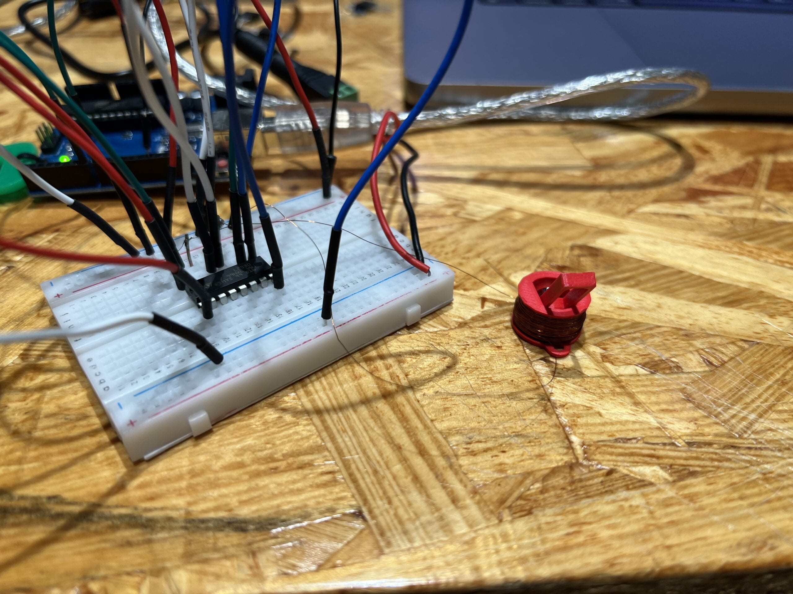
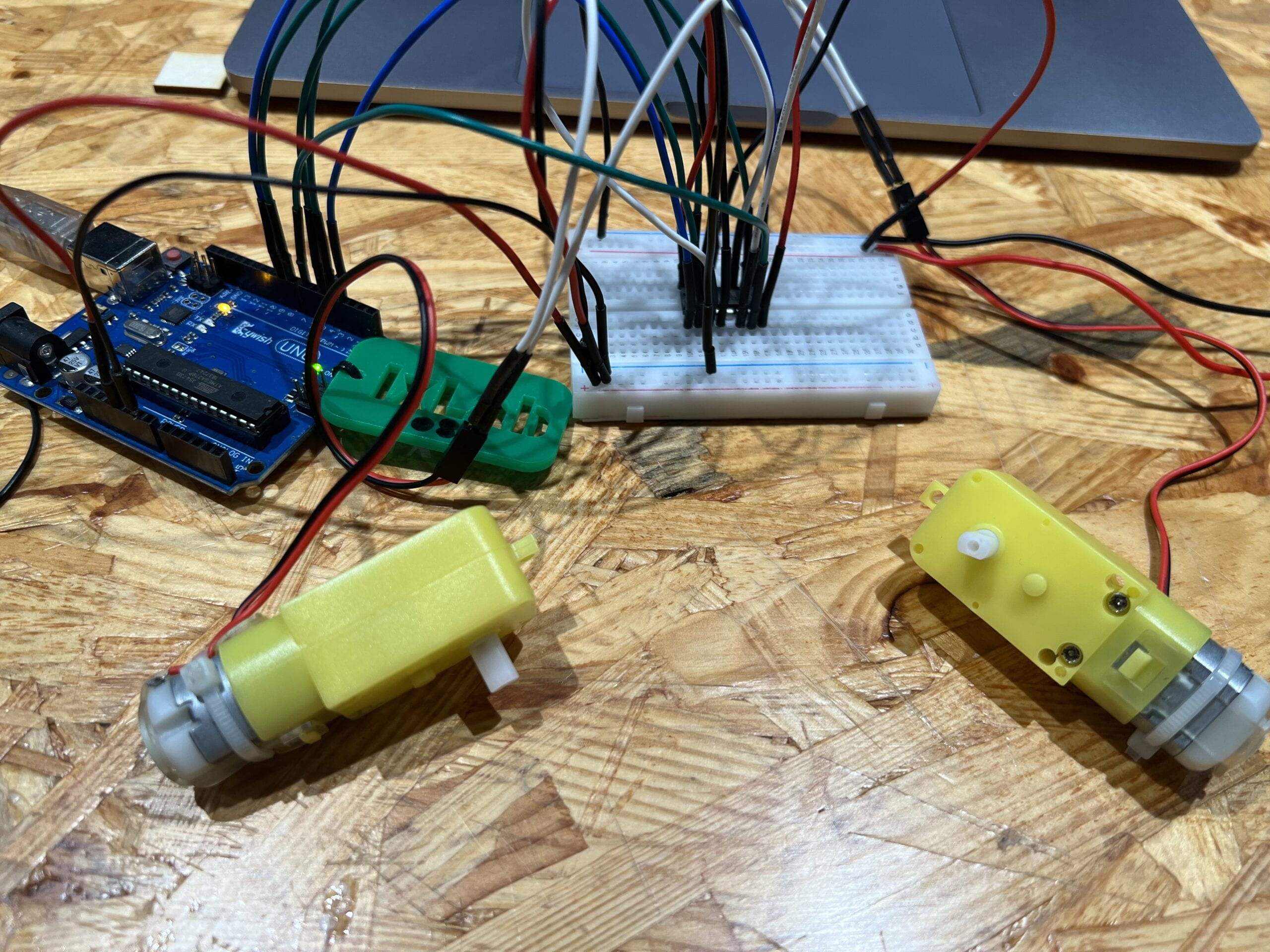
The first change is that I used DC motors instead of stepper motors, for the stepper motors are too big and too heavy, given we need more than one motor on the body, it would not be so practical to install multiple stepper motors onto the dress. On the other hand, the DC motor is small enough that we could easily fit it into the small “pocket” Yasmin made on the front side of the dress.

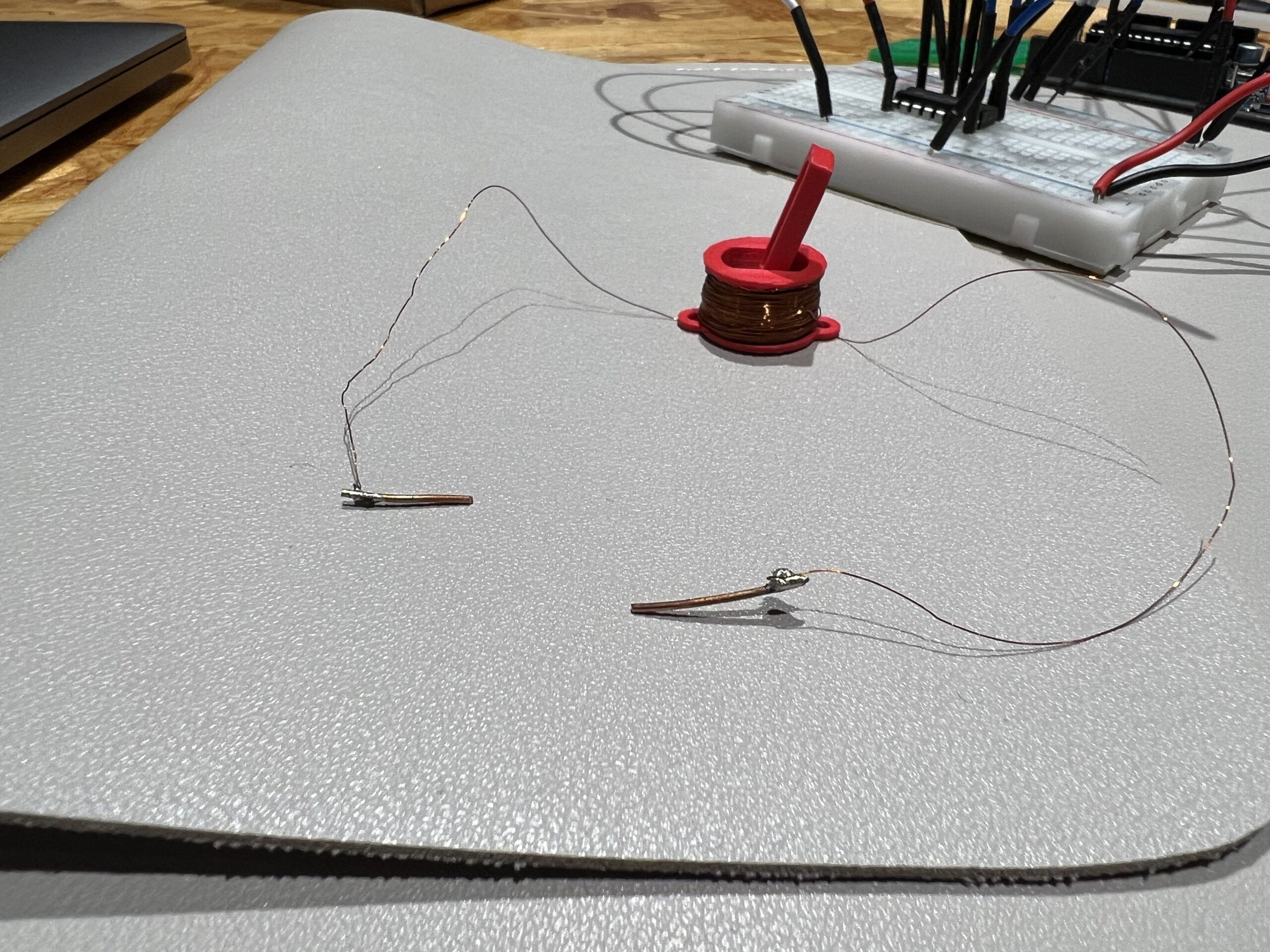
The second change is that instead of one motor pulling one strip of scales, we decided to have it pulling multiple strips, given that having only two strips of scales moving are not that noticeable. However, wiring multiple strings onto the same motor gear was not enjoyable. Several strands of wire can easily get tangled together and creating a mass after the motor rotates a while.

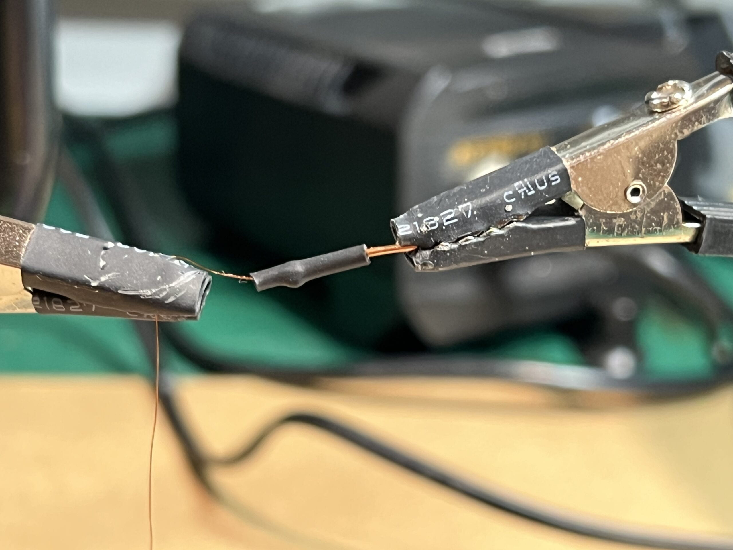
We first made a prototype testing that if having one motor powering several strips of scales is feasible. After noticing that wiring two or three strands of wire is troublesome, we figured out a way to join the three strands together into one strand, and wire only this strand onto the motor. Such technique solved the problem that wires got tangle together, however, another problem occurred that only when the joint string is perfectly symmetrically placed among the scale strips, could all of the scales be pulled up at the same time. If the joint string leans to one side, then only one side of scales could be pulled up. Such problem is due to that unequal strength given to each scale. When the joint wire is not in the exact middle, then some side of scales would get much larger strength than the other side, resulting in the unsymmetrical movements.

To deal with that, we need to place the motor, the string, and the scales in exact positions without any of them moving around. However, that is very hard to achieve as the whole mechanism need to be on the dress, and movements are not avoidable when the model is walking. After trying that technique for some time, we chose to return to the very first solution of several strings on one gear. Rainee found a way to secure the strings so they would tangle with each other easily, but there is still potential tangles from time to time.

Luckily, due to one other major problem in the circuit (mentioned in later sections), I found DC motors that have two ends for gears instead of one. This kind of motor greatly solved our problem as we could simply wire one strand of string on one gear. Problem solved!


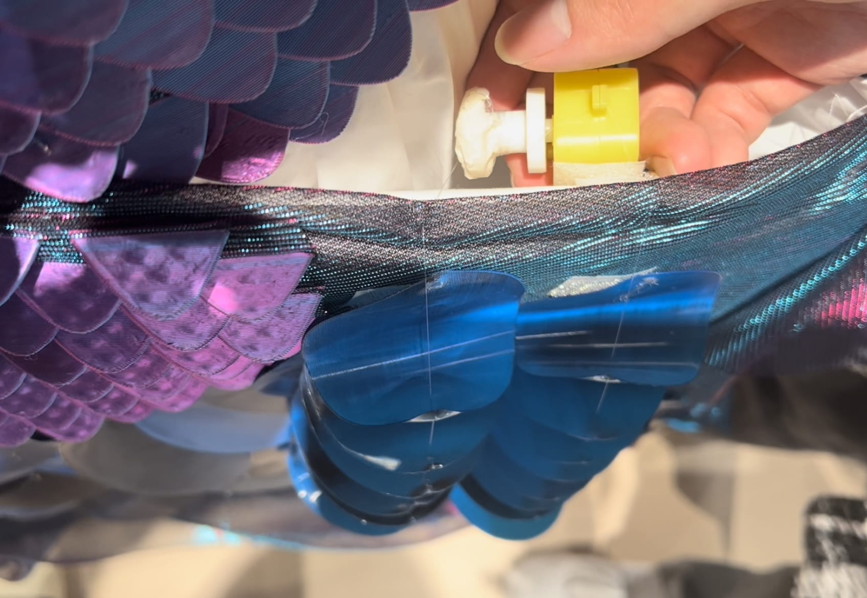
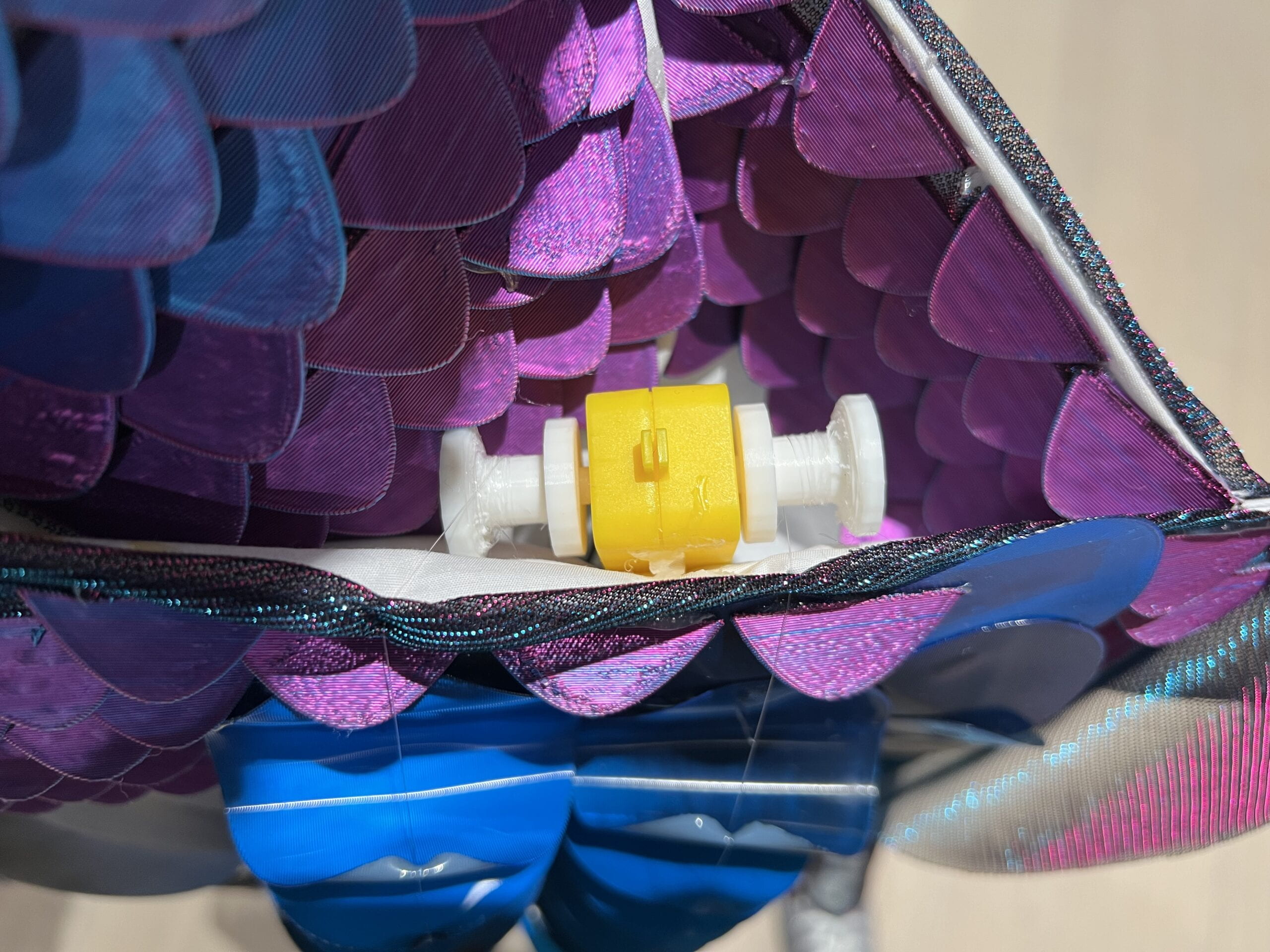
The third change is that instead of having motors above the scales, so that gravity could constantly hold the scales down, we now have the motors hidden in dress pockets so that the strings have a 180 degrees angle, with the strings touching the fabric. I worried for a long time that when motor loosen the string, scales could not automatically go back to initial position due to the Friction of string and fabric. It turned out that with more scales connected together, they would be heavy enough to pull down the strings themselves, therefore the whole mechanism still works.


Circuits

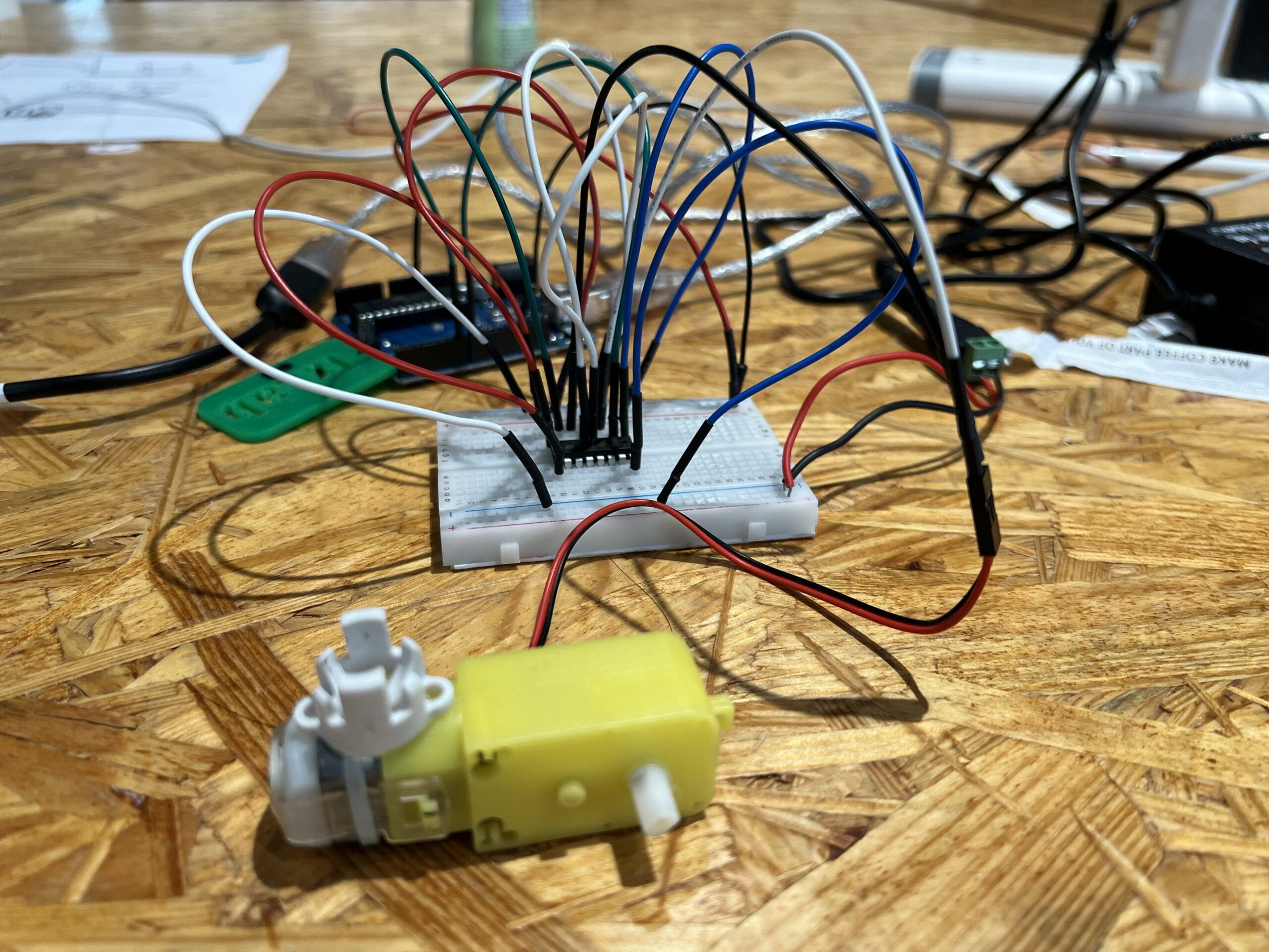
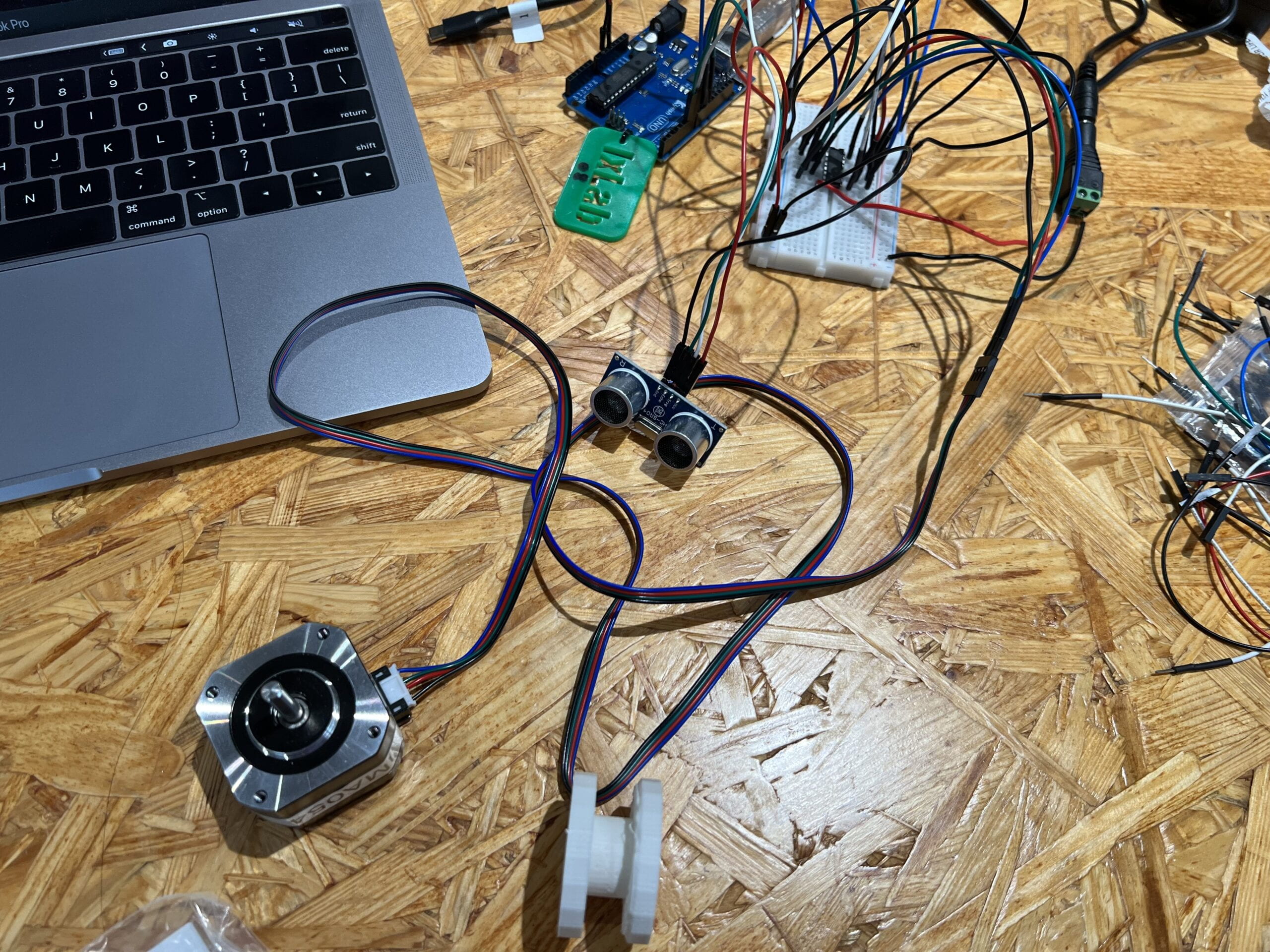
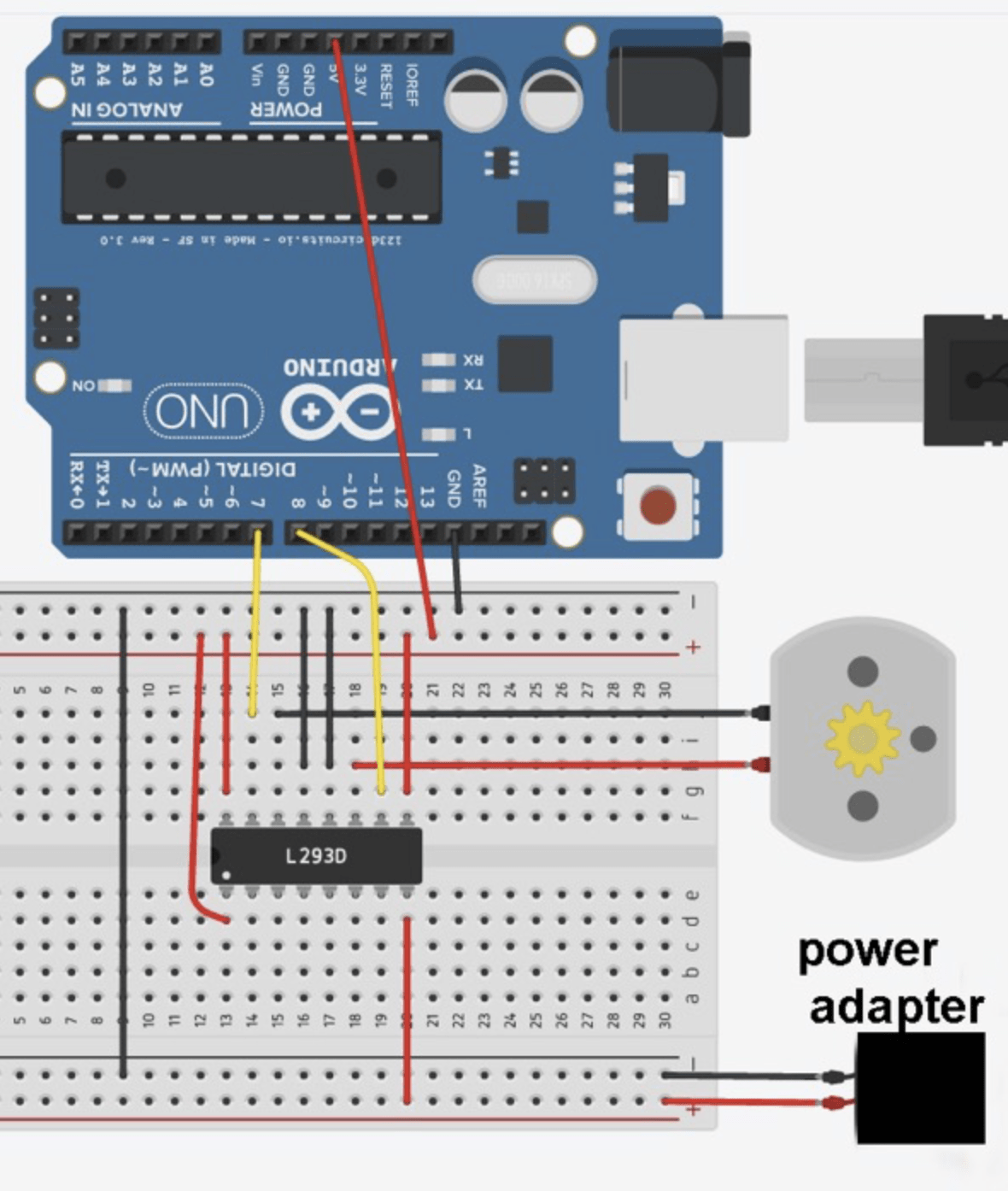
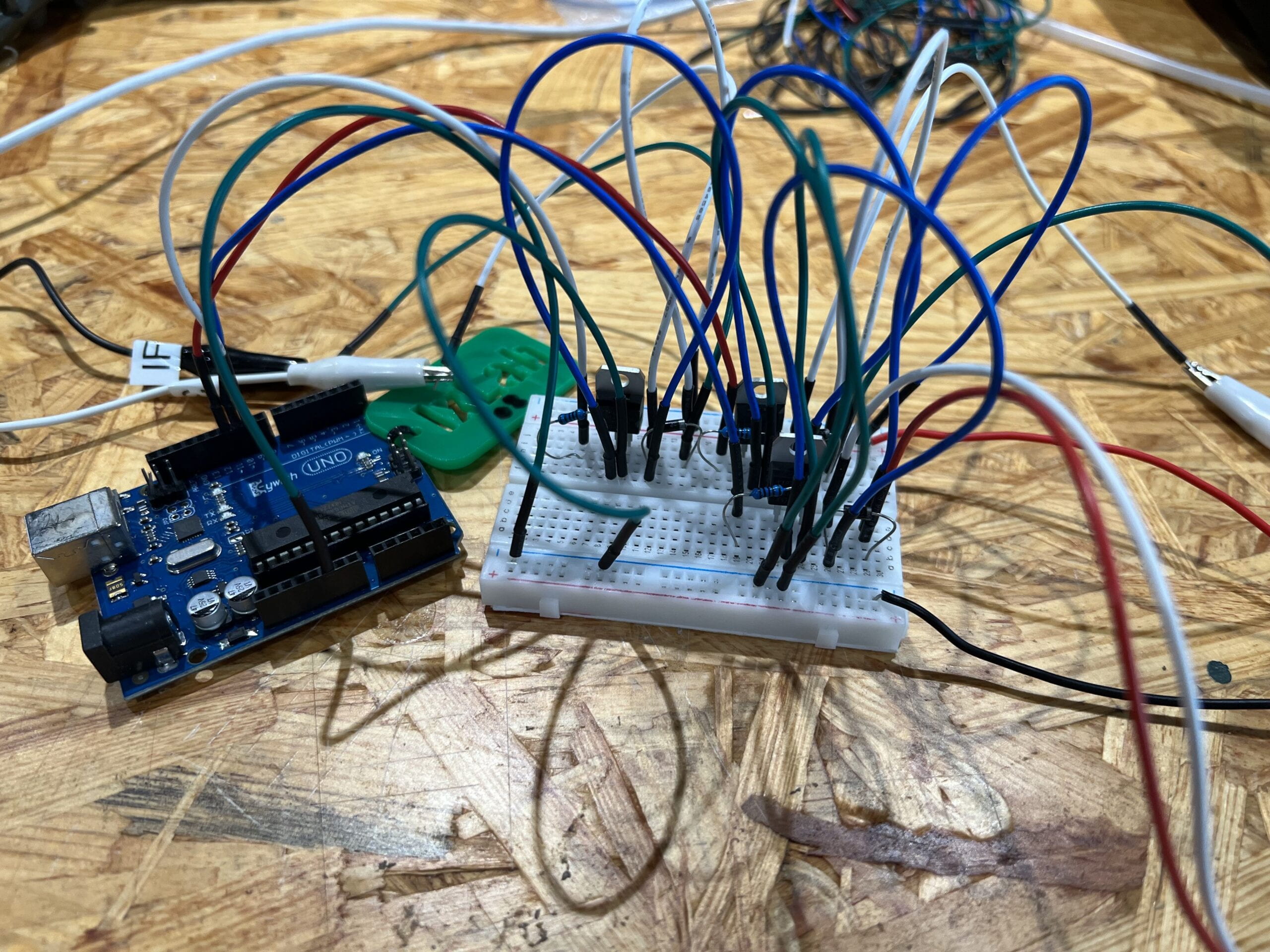
Just as mentioned above that I used DC motors instead of stepper motors, therefore the whole circuits also changes from the kinetic prototype one. Given that I want to control the direction, speed and duration of the DC motor, I would need some more complex than directly connect the motor to Arduino. Utilizing the h-bridge would help achieve my goal. I found one circuit from Last Minute Engineer website, which connects two DC motors using one h-bridge and one Arduino to control the speed, direction and rotation duration. This circuit satisfies all my requirements for this project.

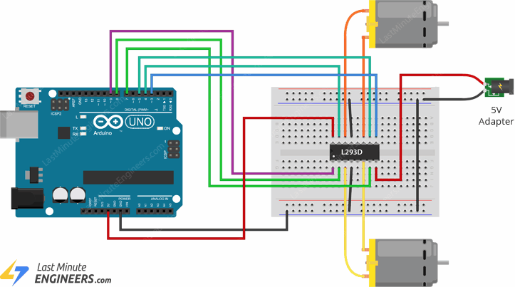
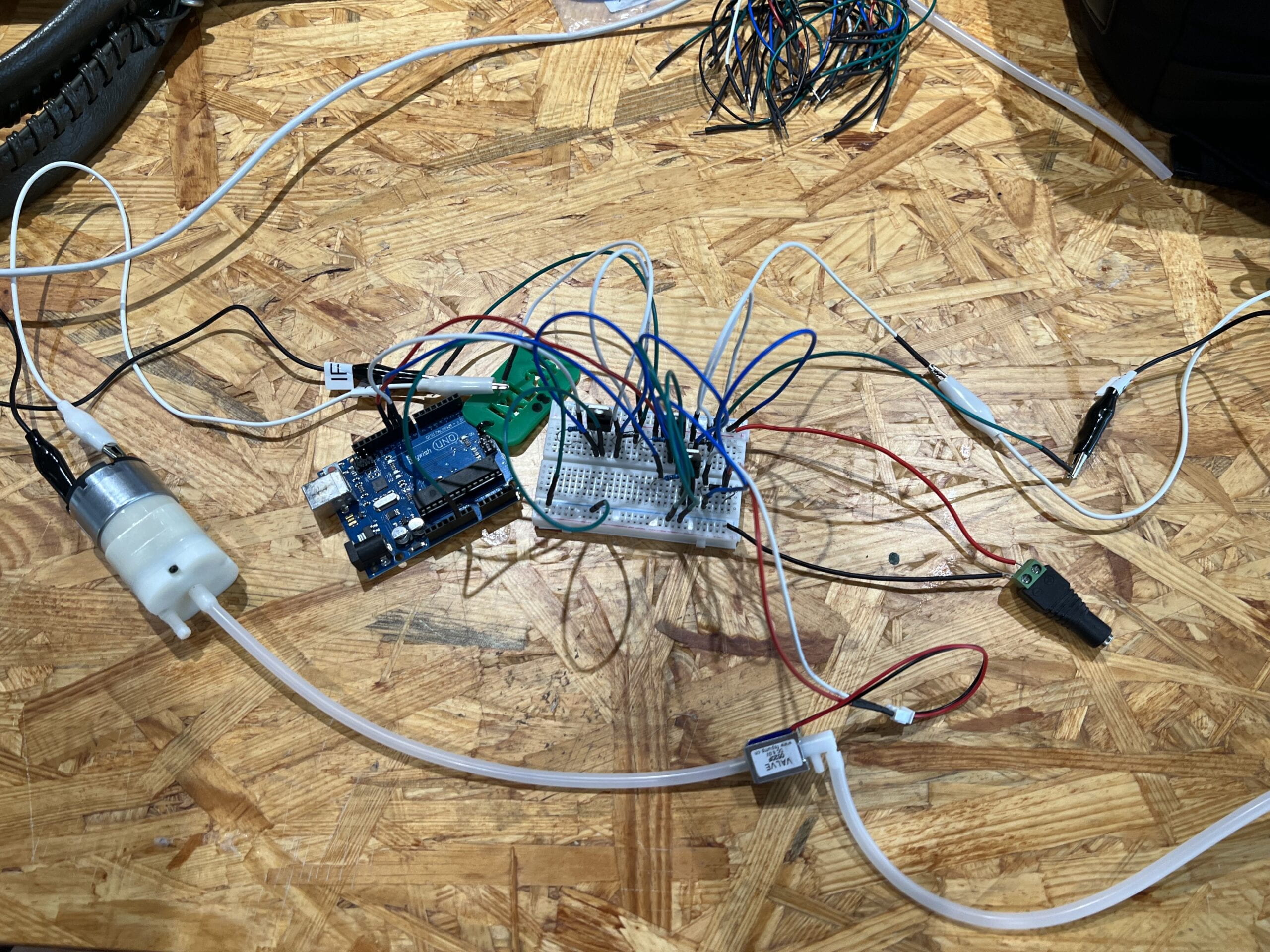
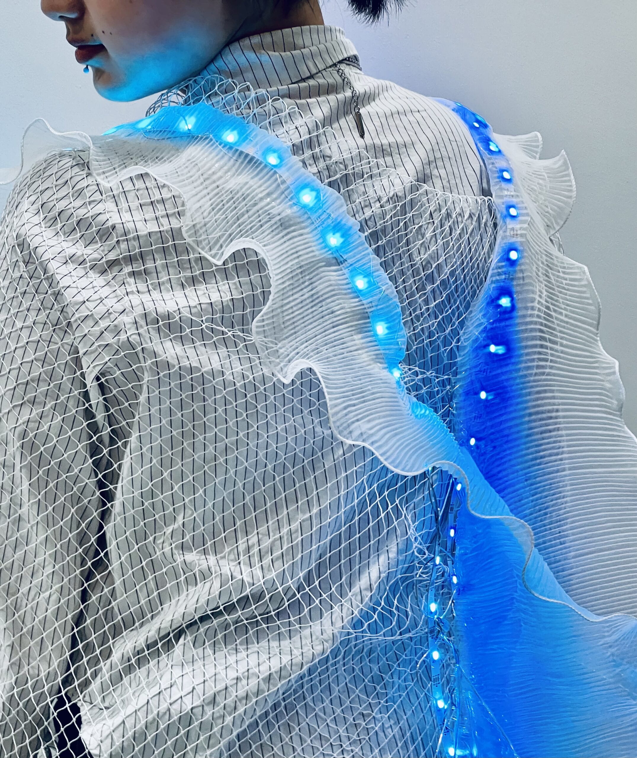
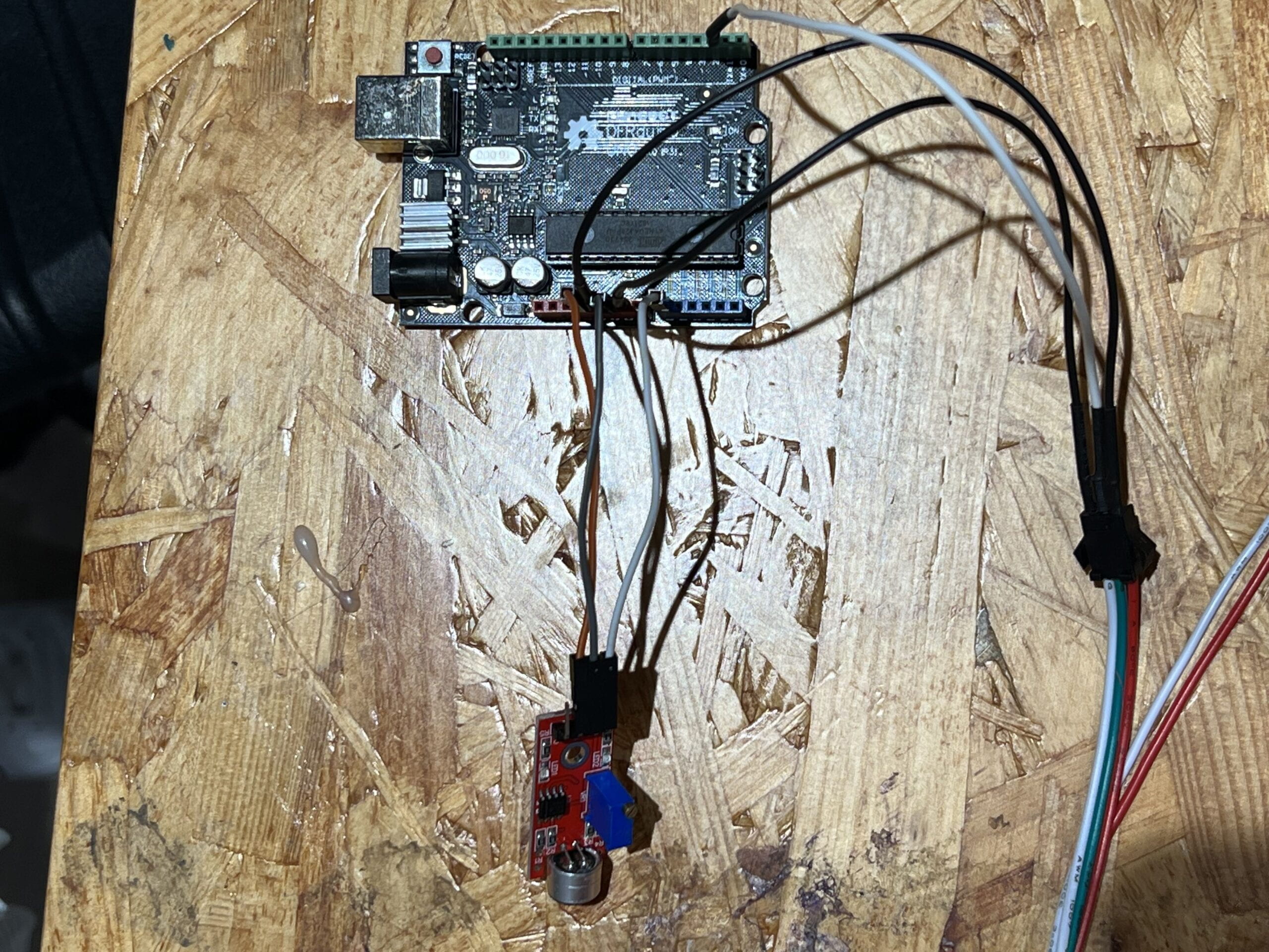
Besides the above circuit, I also added on ultrasonic distance sensor onto Arduino. The ultrasonic sensor is easy to connect, just using two more pins on the Arduino board and connect with power. The final circuit looks like this:


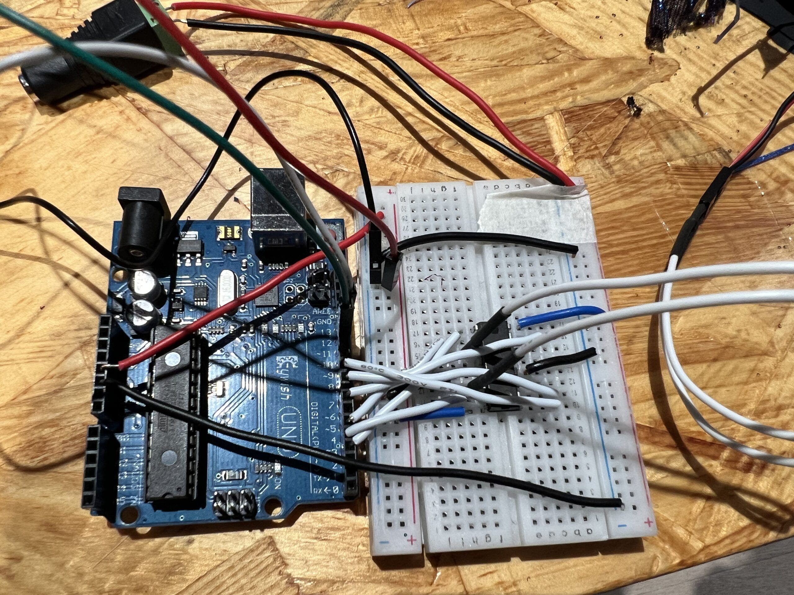
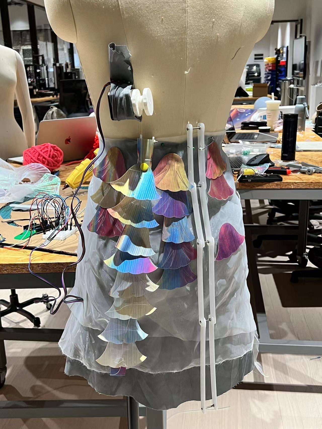
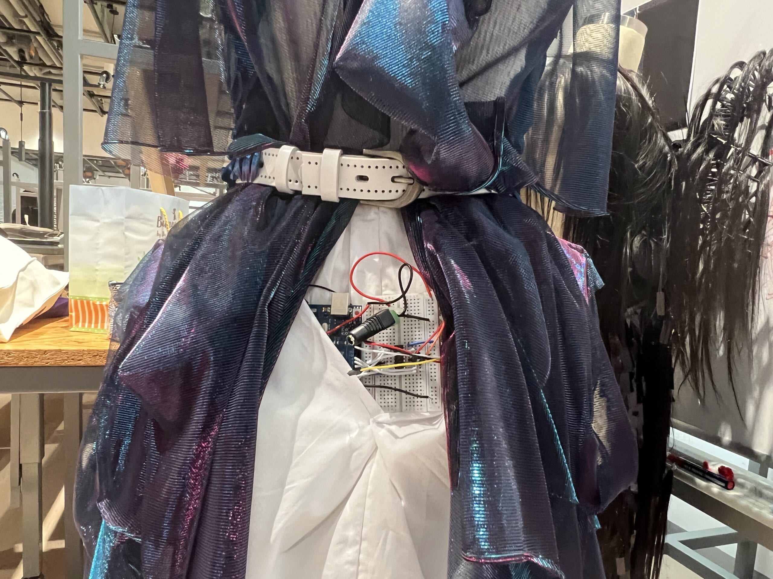
I cleaned up the wires and jumpers, and in this way the bread broad is also securely positioned next to the Arduino, without extra glues or tapes required. In this circuit, we have two DC motors, one distance sensor, one power sauce for Arduino, and one extra power sauce required. The two motors are placed at the two pockets in the front (as seen in previous photos), the distance sensor is placed in the front middle, while all other circuits along with the power sauces are hidden at the back side.

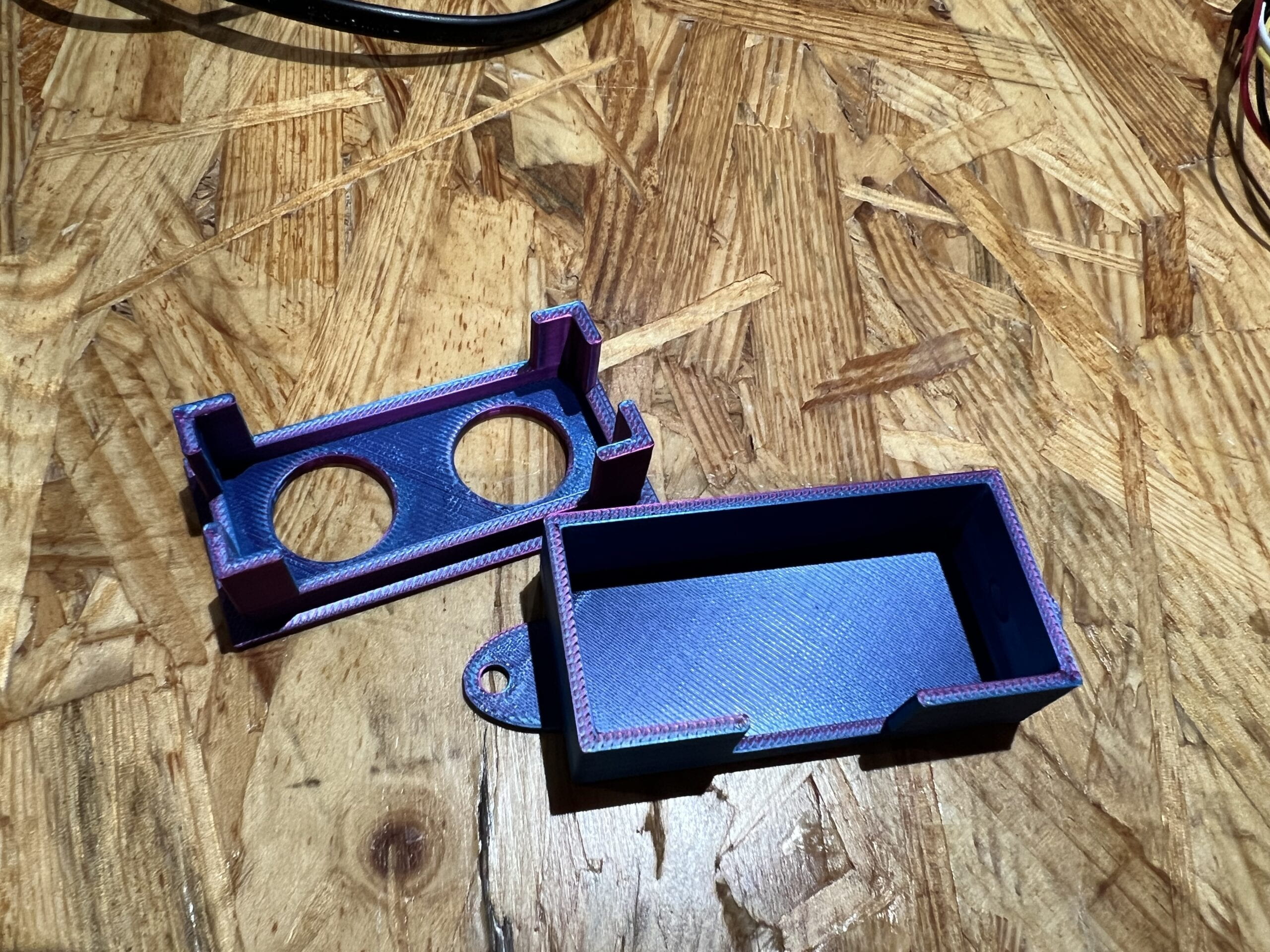
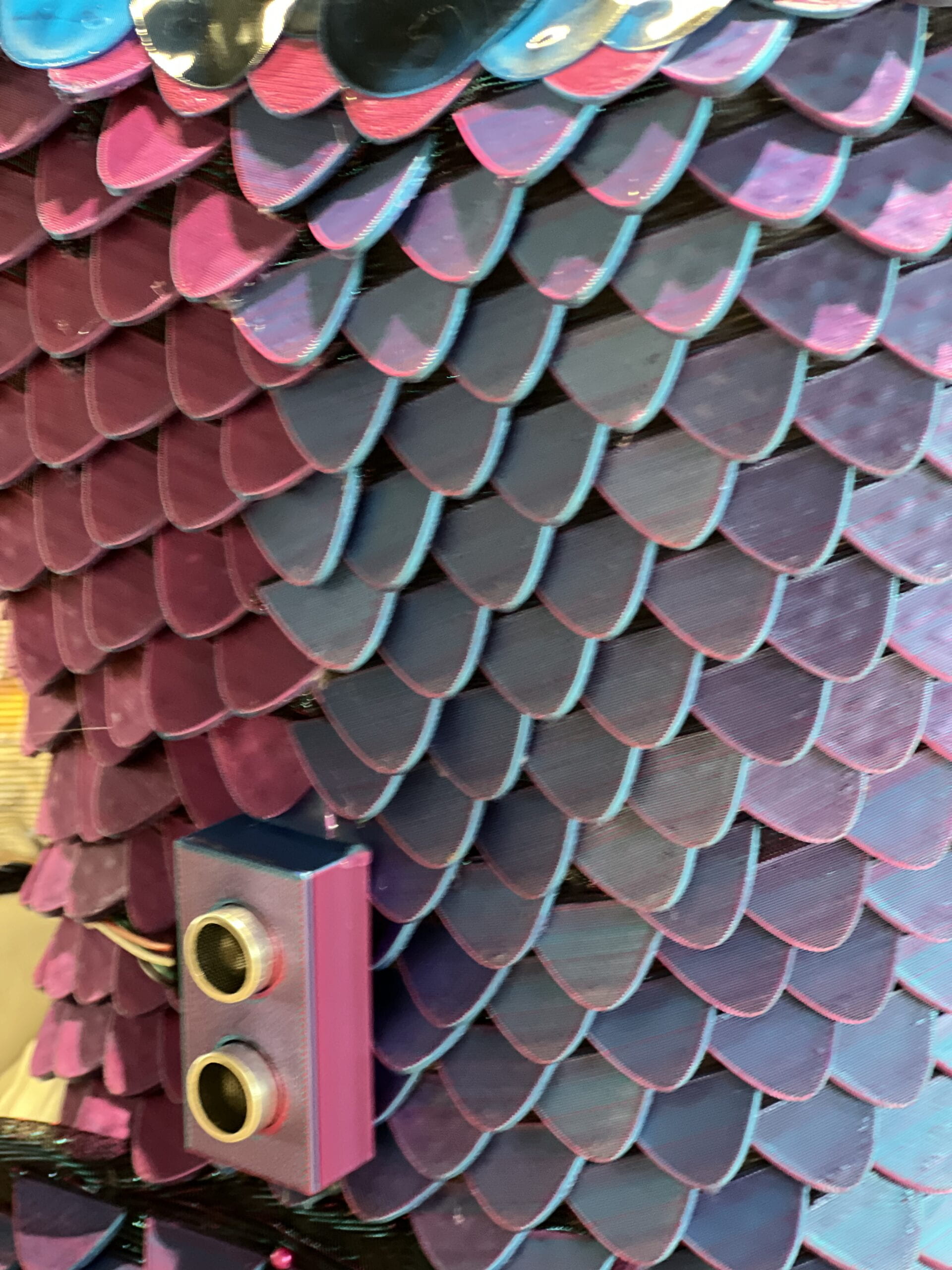
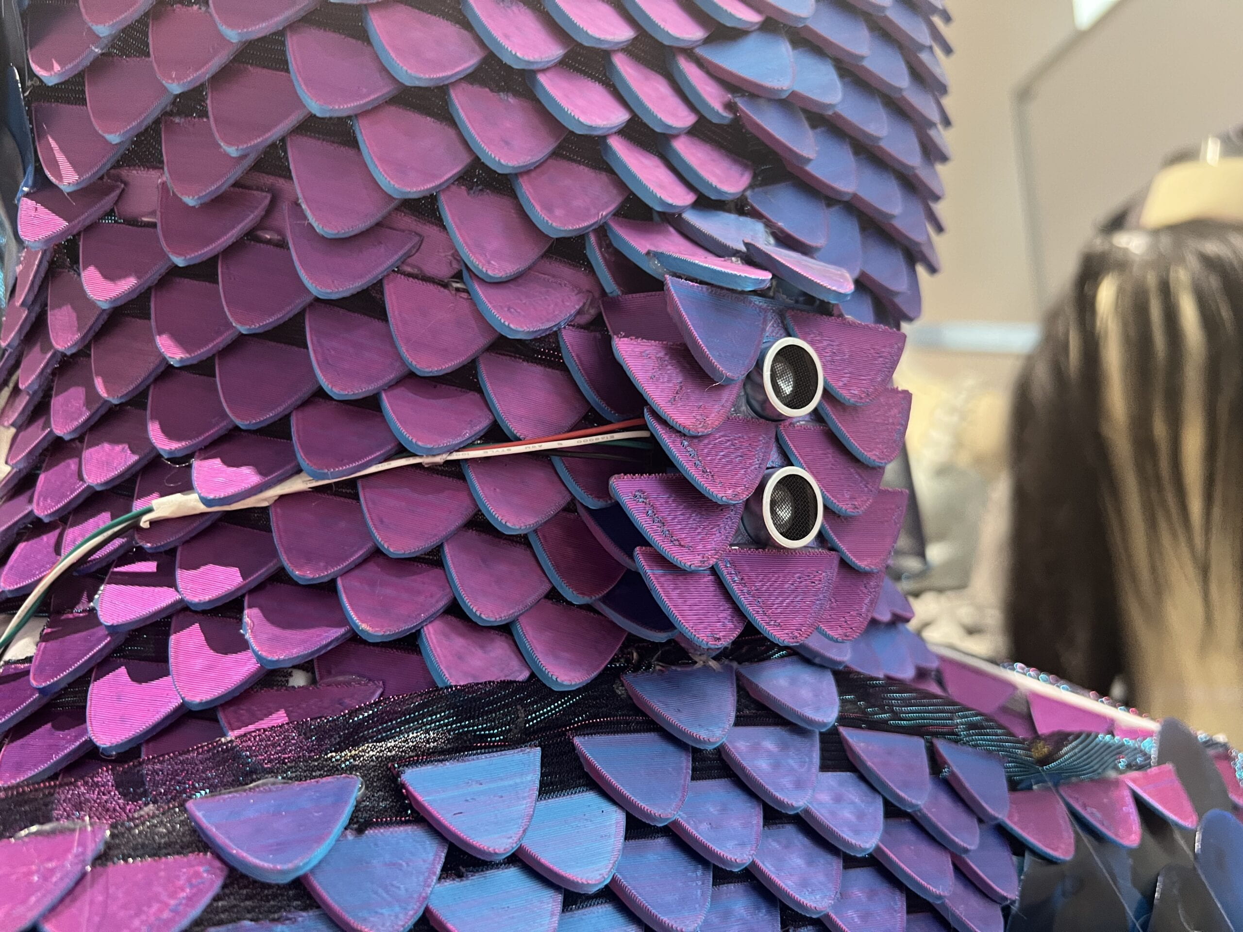
I 3D printed this small box to hold the ultrasonic sensor, which is placed in the middle. I used the colorful PLA trying to hide the sensor, however it is still relatively big and easy to notice. Later, Yasmin used 3D printed scales to cover the box and further hide the sensor. I think we did a good job in hiding the sensor at last, since one of my friend asked that why is there a small protrusion in front of the dress (she did not notice that is a sensor).


As for the Arduino board, bread board, and two power sauces, there are all placed in the back “pocket”, which are covered with many layers of fabric. I think we did a good job in hiding those circuits (I sometimes cannot easily locate our circuits myself). Although I have made all jumpers and wires tight and secure, the only problem I had with the wires where the two jumpers connected to the extra power sauce, which accidentally broke right before the runway show, Professor Marcela helped to glue them together. Regarding this problem, it would be better secured if I have a box holding all the circuits, but I was not so willing to do so as it would take more space, and the circuits could be more visible (or the dress looks less nice). Another potential solution is to further sew or attach the circuits onto the dress.


Codes

Connecting the circuits was not difficult, and so does the overall codes (See full codes at the end of this post). I used the same codes to connect and convert ultrasonic sensor values. While for the DC motor,  example codes provided in the circuit website are straightforward and easy to use.

void directionup(){
  digitalWrite(in1, LOW);
  digitalWrite(in2, HIGH);
  digitalWrite(in3, LOW);
  digitalWrite(in4, HIGH);
}

void directiondown(){
  digitalWrite(in1, HIGH);
  digitalWrite(in2, LOW);
  digitalWrite(in3, HIGH);
  digitalWrite(in4, LOW);
} 

These codes are used to control the direction of rotation, by passing different currency directions to the motor.

  directionup();
  delay(600);
  directiondown();
  delay(550);

The simple delay function is used to control how long the motor rotates. As the motor would remain doing the previous function until a new line of code is given.

void set_speed (int spd){
  analogWrite(enA, spd);
  analogWrite(enB, spd);
}

 The analogWrite is used to set the speed of rotation. What these codes do is actually controlling the input voltages to the motor. And here comes one of the biggest problems I met when building up the circuit. The story goes that everything worked well when I was using controllable extra power sauce, where I normally used 5V-7V as the extra power. However, after trying the 12V chargeable battery (so that we can simply put power sauce inside the dress), both of my DC motors stopped functioning after half an hour. The motors would still vibrate whenever they should rotate, but they would not rotate correctly as we wish. I did not know about the reason that motors fail at first, so I checked everything (from the circuit to the sensor to the codes), and they were all good. After discussing with Professor Marcela, we suspect that the voltage was too high for the DC motors and somehow damaged them. As the working voltage for DC motors are normally 3V – 6V.


Therefore, I changed two DC motors (that is when I changed to motors with two gears instead of one). In order to control the voltages going into the motor, I could alter the motor speed. Lowing the speed to around 90 would give the DC motors 6V of power, when the extra power sauce is 12V. In this way, the motors could function, though at the cost of not able to control the motor speeds freely.

In order to avoid further damage to the motors, I  deleted the part of codes that alters speed when detecting objects in different distance. The final codes are pretty simple. Whenever the distance sensor detects objects coming close to the model, the motors would turn up and down once. After the movement, the sensor would resume detecting the speed.
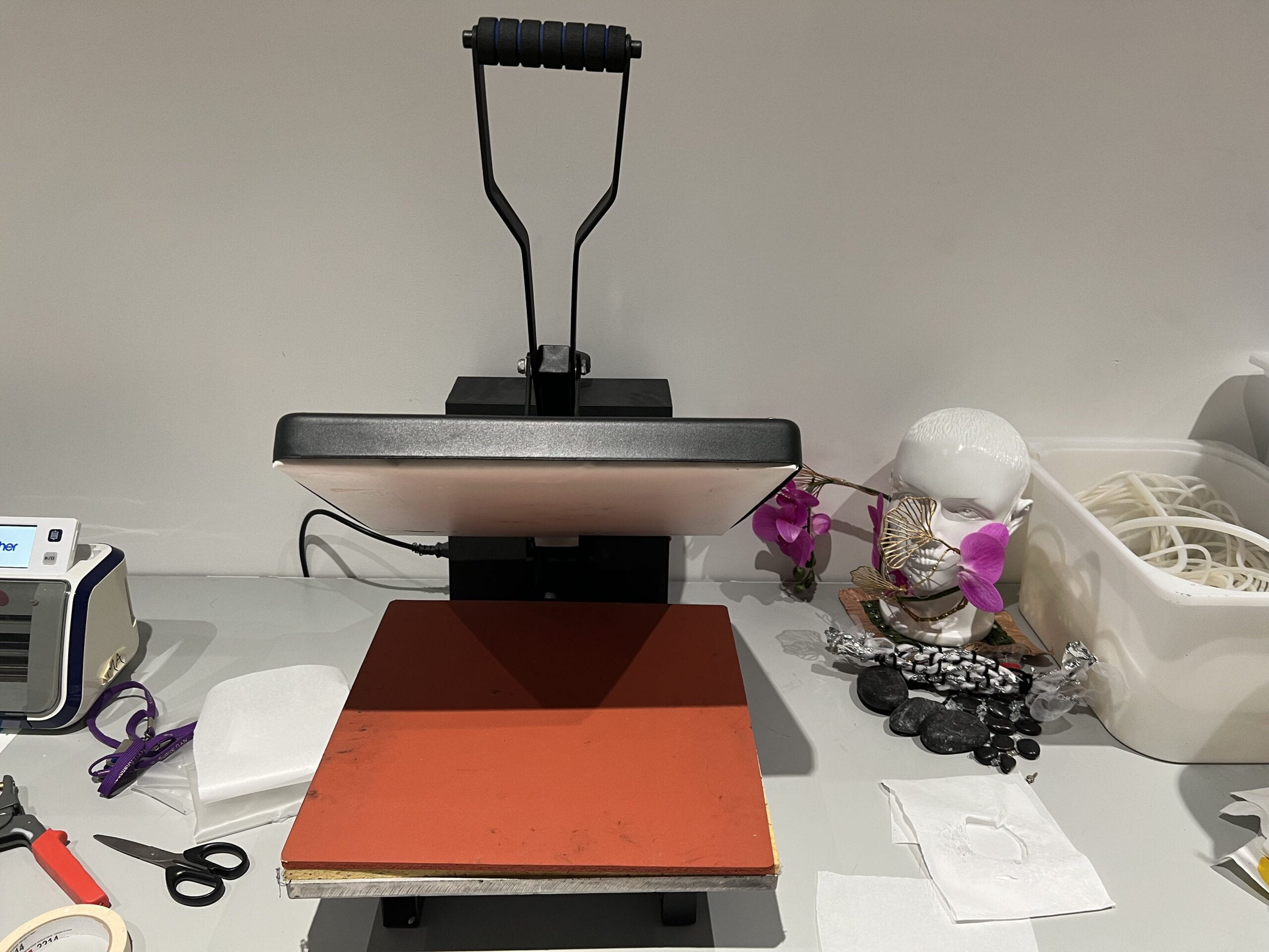
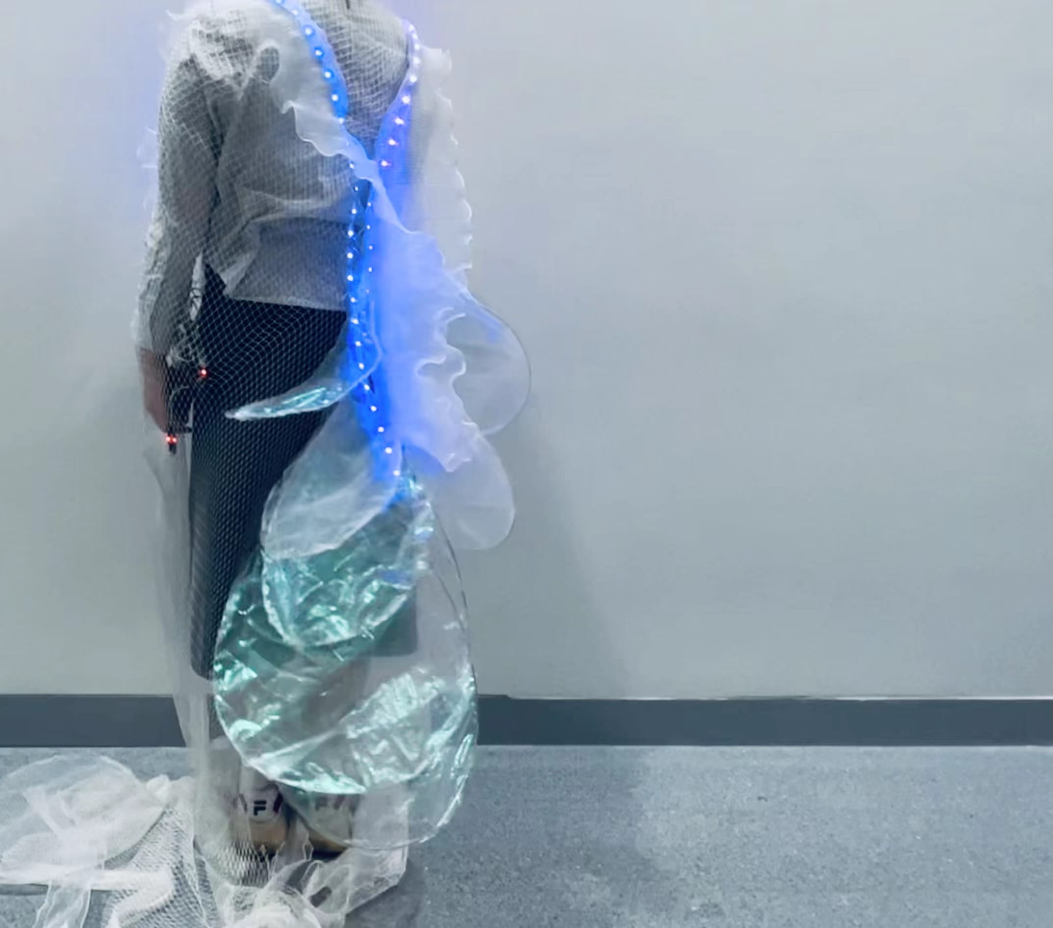
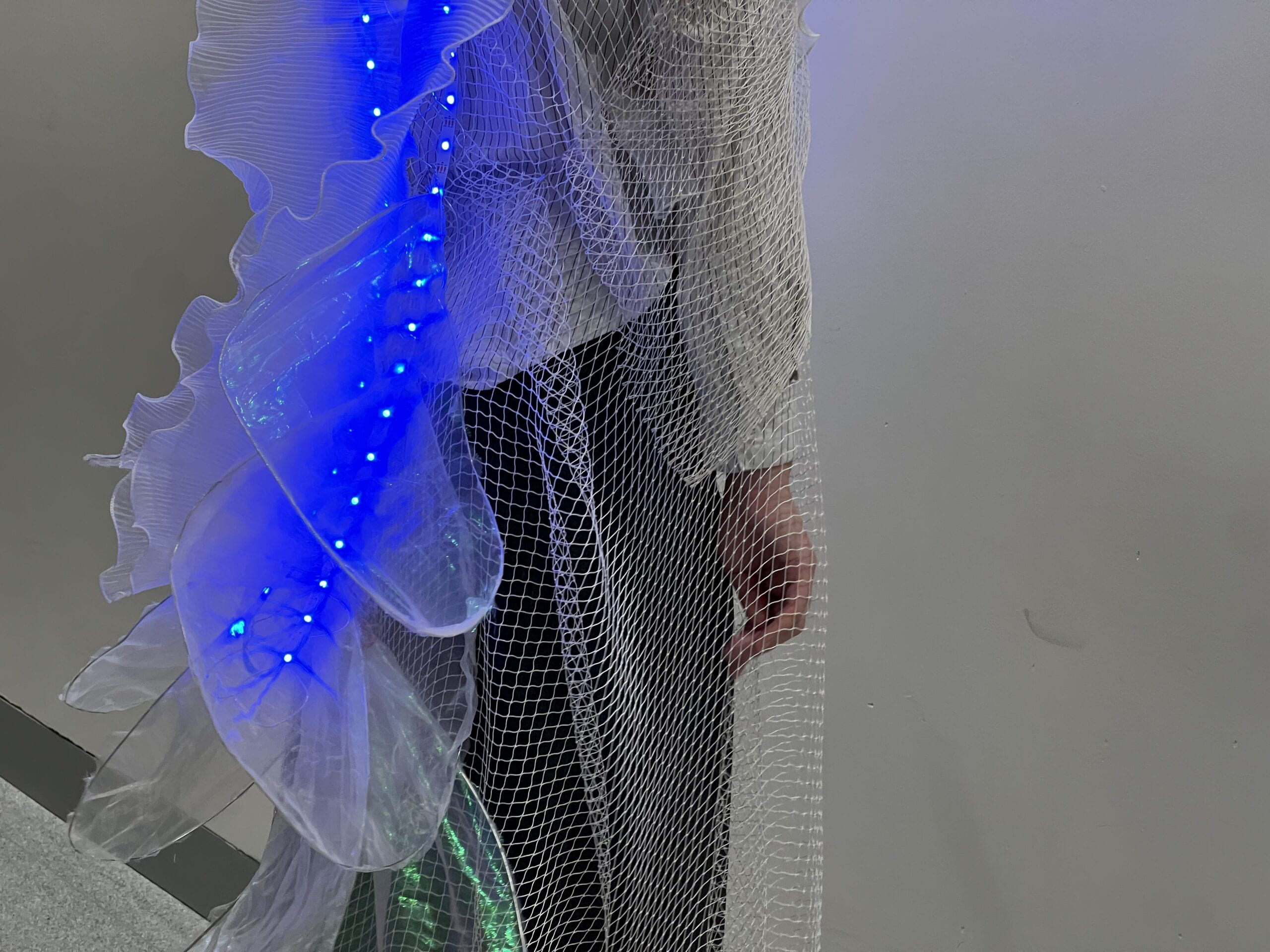
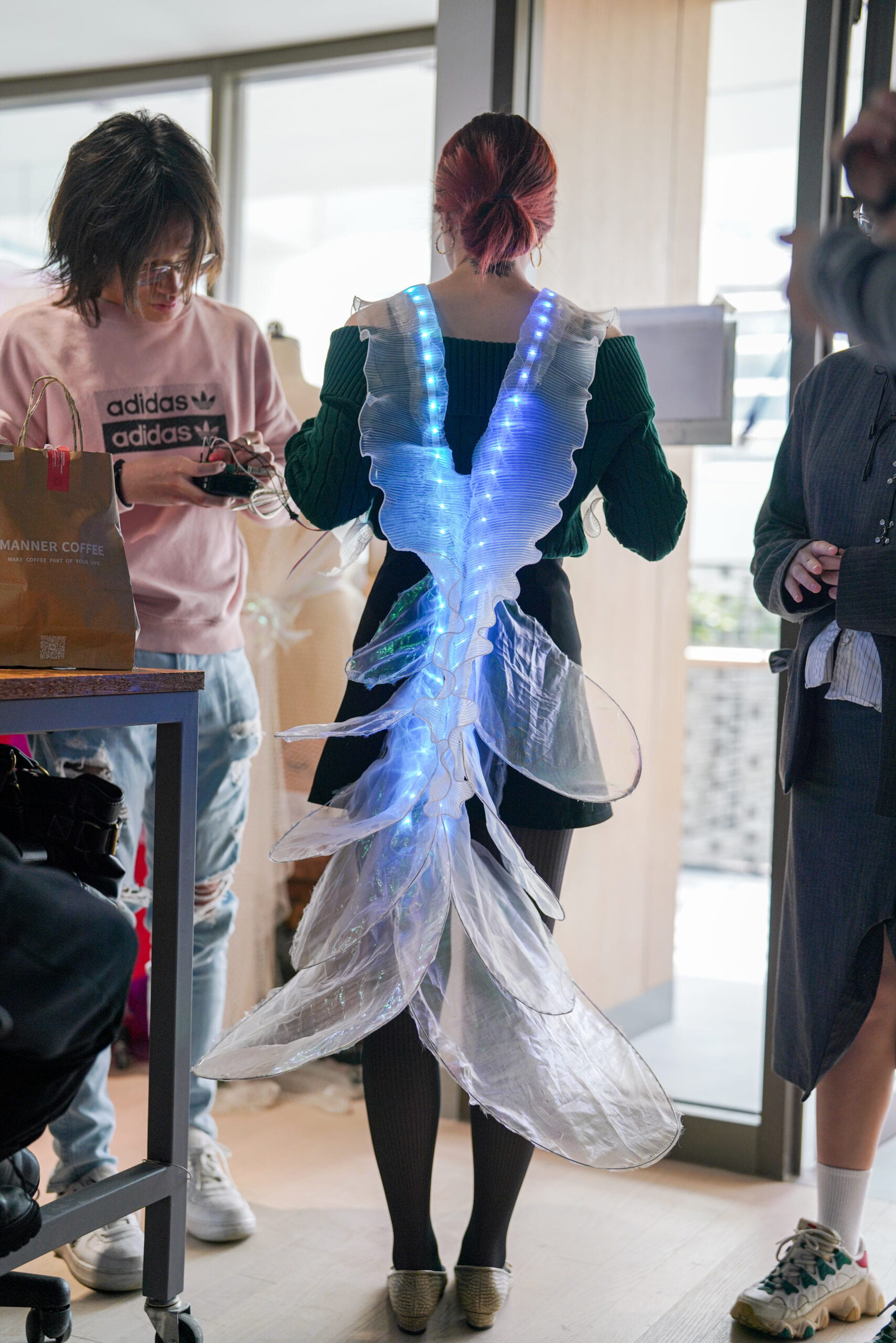
Runway Show

Yasmin was in charge of all the makeup and details for the runway show. I tested and connected the circuits before and after the dress is put on by the model. As for some reflections after the show, it seems our interaction movements are somehow subtle when the model is walking. I think having bigger scales or having moving scales on other part of body would be some potential improvements to what we have right now. Or we could have multiple distance sensors detecting not only the front, but the whole surroundings of the model and react accordingly. 

Conclusion

Despite all the difficulties and frustration, I really love the final piece Betta. I want to thank my teammates for their creativity, inspiration and hard work. I am more than fortunate to take Interactive Fashion as my last IMA course and have Betta as my last IMA project in my undergraduate study.

// Motor A connections
int enA = 9;
int in1 = 8;
int in2 = 7;
// Motor B connections
int enB = 3;
int in3 = 5;
int in4 = 4;
// defines pins numbers
const int trigPin = 12;
const int echoPin = 13;
// defines variables
long duration;
int distance;

void setup() {
  pinMode(enA, OUTPUT);
  pinMode(enB, OUTPUT);
  pinMode(in1, OUTPUT);
  pinMode(in2, OUTPUT);
  pinMode(in3, OUTPUT);
  pinMode(in4, OUTPUT);
  pinMode(trigPin, OUTPUT);
  pinMode(echoPin, INPUT);

  digitalWrite(in1, LOW);
  digitalWrite(in2, LOW);
  digitalWrite(in3, LOW);
  digitalWrite(in4, LOW);
  Serial.begin(9600);
}

void loop() {
  distance = detect_distance();
   Serial.println(distance);
  if (distance < 10){
    set_speed(90);
    oneround();
  }
  else {
    set_speed(0);
    turndown();
  }
}

int detect_distance() {
  digitalWrite(trigPin, LOW);
  delayMicroseconds(2);
  digitalWrite(trigPin, HIGH);
  delayMicroseconds(10);
  digitalWrite(trigPin, LOW);
  duration = pulseIn(echoPin, HIGH);
  distance = duration * 0.034 / 2;
  return distance;
}

void oneround(){
  directionup();
  delay(600);
  turndown();
  delay(700);
  directiondown();
  delay(550);
  turndown();
  delay(700);
}

void set_speed (int spd){
  analogWrite(enA, spd);
  analogWrite(enB, spd);
}

void directionup(){
  digitalWrite(in1, LOW);
  digitalWrite(in2, HIGH);
  digitalWrite(in3, LOW);
  digitalWrite(in4, HIGH);
}

void directiondown(){
  digitalWrite(in1, HIGH);
  digitalWrite(in2, LOW);
  digitalWrite(in3, HIGH);
  digitalWrite(in4, LOW);
}

void turndown(){
  digitalWrite(in1, LOW);
  digitalWrite(in2, LOW);
  digitalWrite(in3, LOW);
  digitalWrite(in4, LOW);
}

Interactive Fashion | Assignment 10

In-class Exercise

For the in-class exercise, I followed the tutorial and steps to create the vonoroi pattern, and added two points so create height differences for the pattern. The overall process was not hard to follow, and the commands in Grasshopper were straightforward as I had used most of those commands in previous weeks.

After-class Assignment

As in our final project, we wish to create a dress mimic ocean creatures, we would like to explore if we could 3D print fishing scale liked shapes onto fabric, so that the printed scales could cover the dress with movements.

To create fishing scales models in Rhino, I first thought about lofting a base polygon to a point. After doing some research, I found that hexagon is often used for the bases of scale shapes. Then, I tried to draw a hexagon, and set a point to loft them. The shape does not look very nice, so I thought about adding a base before lofting.

The overall shape does not really resemble a fishing scale, also that the edges are too sharp. Along with the problem that I would need multiple of such scales and aline them together, I decided to build the model with the in-class exercise commands.

I modified the commands used in the exercise, keeping the overall logic, but changing the base curves and the position of the upper points. I also removed the parts where the heights would differ according to selected points.

As I decided to use hexagon as base shapes, I manually drew several hexagon curves and assigned them to the curve command in Grasshopper (because I was not sure how to create hexagon shapes directly in Grasshopper). As for the center  points, instead of having them lifted up 10 millimeters, I also moved them along the x-axis to make them look like real scales.

In the mean time, I found such models do not resemble fishing scales so much, and I searched online for similar models and tutorials. I found this blog for 3D-printed dragon scales. In which it provides a STL file for the models. So I decided to print both my model and that well-designed dragon scales.

Then, I put both STL files into the 3D printer app, set for the first layer to be thicker and place a stop after the third layer. One difficulty I encountered was when putting the fabric onto the 3D printing surface. Although I applied tons of glue on the fabric, the wind generated in the printer still blows the fabric away constantly. Therefore, I also used paper tapes to further secure the fabric, and resumed the printing.


The final outcome looks pretty nice, and the models I made looks much better than I previously imagined. Some improvements are that I could shorten the gaps between each scale, which is to scale up the model a little bit, as now each scale is pretty far away from each other, and the gap can be easily observed. One other improvement is to round the edges as now they are pretty sharp and harmful.

The scales look really good on the model, and we could print them into other colors and use them in our final project.

Interactive Fashion | Assignment 9

In-class Exercise

For the in-class exercise, I followed the tutorial to create the shape of a vase, using Rhino and Grasshopper. Though a bit complicated, the tutorial was not difficult to follow and I did not meet any major problems in replicating the overall model.

It is also very fun to play with the parameters and see how the vase changes its shape and angles.

After-class Assignment

Regarding the assignment, the producing process is much longer, resulting in a much bigger Grasshopper graph. but the tutorial is very straightforward and easy to follow, so I also did not encounter much difficulties.

In the later parts of this assignment, I found my laptop slowing down a lot, and I was not able to change the parameters in the most beginning steps (such as the seed and the number of points) easily, as one small change would result in the laptop computing for a relatively long time.

I baked the Grasshopper result to generate the modeling for this wearable. It seems the model is easier to be distinguished when putting on a model, instead of having itself shown.

Although the tutorials are easy to follow and I could remake such models. I could not completely understand what I am doing actually. Mainly because I am not familiar with all those commands in Grasshopper, and the purpose of using each command. It seems more study and knowledge towards the commands and their interactions are required if I would like to create a 3D model using Grasshopper all by myself.

Interactive Fashion | Assignment 8

Models in Rhino

For the in-class exercise, I followed the instructions provided by Professor Marcela, both in-class demonstration and from the exercise files. The instructions are relatively easy to follow, and in the building process I mainly met two problems.

The first being that the BooleanUnion of the pipes taking forever time, and sometimes raise warnings. I learned to solve it by not uniting everything at the same time, but to take small steps of getting a few of them together, and then union those parts together. While for the warnings, I could separately look into details and adjust the sizes manually, as most of them are due to one pipe being too big or at the wrong position.

The second problem I met was for the ptOffsetPoints, where the points I generated are always inwards instead of pointing out. Resulting in the final model in a reversed shape.


Regarding the after class assignment, the online instructions are also easy to follow, and I did not met major difficulties in building the model.


3D Printing

I exported the 3D modeling file into .STL, and used the Ultimaker Cura software to generate the 3D modeling. I used the tree shape support, with the angle of 80 degrees, and shown in class.

The first half of the modeling process was smooth, but I later found out that one part broke a little bit when the printing was about to finish, resulting in one pipe not able to join together in the final piece.


I suspect the reason of such break for either the model being not well built or the support being not enough. However since the other part shows no problem, I think I could improve the printing by having more supports.

I glued the breaking points together with glue guns and had this final piece.

Interactive Fashion | Kinetic Prototype


Ideas and Design

For this project, Rainee and I decided to continue the concepts and designs in our first project, to create biomimetic fish body. As this project is about exploring mechanism that could create movements for the wearable, we think about elements that would move for fish and ocean creatures. One of the most intuitive element is the fishing scales, which would react to not only its own movements but also the surroundings.

We get inspiration from work by Casey Curran, with the mechanism that would unfold pieces by pulling strings.

Regarding the interaction part, we decided to use distance sensors to mimic the scenario where other lives or items are approaching the ocean creature. When objects are dectected within a certain distance, the creature would show defensive movements, where the fishing scales would have rapid movements to either warn the approaching creature or to run away quickly.

Designed by Rainee

Therefore, the major part of this project is to experiment with mechanism and and materials to mimic the fishing scales movements. We plan to place such scales on the lower half of the body. Instead of making every scales move, we decided to separate scales into two parts, the positively moving ones, and the negatively moving ones. We design to have strings on one fraction of the scales that would move when pulling the strings. Other scales are not connected to the string and motor, but would be overlapped with those positively moving ones, so that when those scales unfold, these negatively moving scales would also move, not due to the string and motor, but due to the movements of surrounding scales. In this way, we could greatly reduced the number of motors used, and having different movements for scales in different positions, making the whole movement more dynamic.

One other movement was to have the dress itself moving, with the “bones” of the structure lifting up and down, the whole dress would move upwards and downwards. Such behavior resembles the movement of jellyfish and other soft tissue creatures.

(See detailed designs and concepts in Rainee’s Post)

Mechanism & Materials

Fishing Scales

Continued upon assignment 7, we continued to explore both the mechanism and materials for the fishing scales. We decided to use the mechanism of jointing every scale to one string, so that when the string is pulled, every scale would move at the same time to mimic the movements of scales unfolding. Several major tasks to solve are 1. explore the joining position of fishing scales to the string, 2. the attachment of scales to the base clothes, 3. the material of fishing scales, and 4. the motors used for the movements.

In previous prototypes, we tried to make holes both at the bottom and at the top edge of the scales. When string holes were at bottom, pulling a shorter distance could lift the scale up, but at the cost of requiring more strength. Having holes at the top edge is the opposite situation, when longer string needs to be pulled, with relatively less strength. We first tried all holes at bottom or at top, finding that neither strategy worked very well. They all faced the problem that the first few scales would unfold greatly, but the scales at bottom would have much less movements. 

After finishing the kinetic prototype, I explored again with the position of holes. This time, I first made all the holes at bottom and then tried to make them all at the very edge of the scales. I found out the main reason for the latter scales to have little movement was the movement of the base. If all strings are secured and the base move no more after fixing everything, the scales could move just fine. However, once the base moved a little bit, so that the string between two or more scales could become either too tight or too loose. In this situation, the scales would have movements to different extents.


As for the attachments to the base clothes, we designed several different ways. Initially we had the idea of using acrylic as scales, so the scales could not be simply glued or sewed to the base, and we designed to use hinge joints to connect the acrylic scale with the base. We used 3D printing to build the hinge joints. The first one printed was too small that the inner structure was not clearly printed, and it easily broke from the middle. Then we tried a bigger second one, however it also did not function as desired. We hope the hinge joint to have a hollow gap so that it could rotate freely, however with the given size, 3D printer could not accurately print the structure. Along with other reasons such as the long printing time and probabilities of failing, we decided to not continue with 3D printing. Therefore, we gave up the idea of using hard materials for scales, and turned to soft materials such as paper and TPU.


When using soft materials, we no longer need to use hinge joints. Professor Marcela provided us with buttons that could be easily installed to join the scale and the base clothes together. And we used these buttons for this project. One minor problem is that such buttons are too large, as the fishing scales are rather small. The buttons do not look so good on the scales and would prevent us from making holes at the very bottom of the scales. Therefore, we might continue to try different joints for our final project.

As mentioned above, we discarded the idea of using hard scales and turned to soft ones. The major problem was that most materials are too soft, so that when they were lifted up, the scales might not be able to lift other negatively moving scales. We tried to use TPU, but it was too soft to hold other scales. Thanks again to Professor Marcela, she gave us one kind of soft fabric that is strong enough to hold other scales, and at the same time very beautiful, which greatly resembles the real fishing scales.


Regarding the choice of motors, as documented in the previous blog, we tested the DIY actuator, which turned out to be not powerful enough. I then left with three choices, servo motor, DC motor, and stepper motor. I designed the way to use motors just like kites and fishing rods, where the motor rotates would prolong or shorten the wire. In this sense, I decided to not use the servo motor mainly because the servo motor is too small and could only rotate for 180 degrees. Therefore, it could not prolong enough length of wire to pull the scales up. I then quickly tried a small DC motor. The main reason for me to not use it was that I did not figure out the way to change its rotate speed through codes, but only through controlling the power adaptor. I would probably give DC motors another try in the future.

I used the stepper motor at last, because I could accurately control the angles of rotation and its speed, so that I could pull the string to the exact position I wanted. However, the downside was that the stepper motor is too heavy, it might be a problem if we want to use multiply motors in our final work.


Bone Structures

We designed the bon structure to also be controlled by strings, not using motors but using user’s own arms. I wanted to connect the bottom end of the structure to the user’s wrist. With the top end of the structure fixed on the dress, once the user lift its arm, the dress would also be lifted.

To achieve this effect, Rainee and I designed the joint that could rotate, and utilized laser cut to create the structure. We cut acrylic boards into several strips with different length. By jointing these acrylic strips together, we obtained this structure that is strong enough to hold clothes and able to bend. After cutting these boards out, we found that we could actually narrow these strips further and shorten the length of each one, so that the angles of bending could increase.


Since this mechanism does not involve motors and is much intuitive than the scales one, we did not meet much trouble in creating the prototypes.


Circuit & Code

The circuits and codes are used to control the stepper motor and the distance sensor on the scales mechanism. The overall building process was not so difficult.

Just as mentioned before, we decided to use the stepper motor for this prototype. The circuit is relatively complex, but not difficult to build. One H bridge is used to control the stepper motor, just like the circuits in previous weeks.

In order to have the stepper motor works like fishing rods, I need one wheel that has larger radius than the stepper motor itself, so that less rounds of rotation is required to pull up strings for the same distance. Thanks to Johnny who provided me with the digital model of wheel, I 3D printed the wheel that can be inserted into the motor. It turned out that the hole in the middle of the wheel was not big enough for motors, so I used a hand drill to enlarge the hole a little bit. The 3D printed wheel worked very well to hold the wires.


After measuring the distance required to pull the wire, I changed the codes so that the stepper motor would rotate the exact angles to pull up and release the wires, so that the scales would move up and down.

As for the distance sensor, I used one ultrasonic distance sensor that could detect the distance of any object facing it. I used the sample code to control the distance sensor and calculate the distance in centimeters.

int detect_distance() {
  digitalWrite(trigPin, LOW);
  delayMicroseconds(2);
  digitalWrite(trigPin, HIGH);
  delayMicroseconds(10);
  digitalWrite(trigPin, LOW);
  duration = pulseIn(echoPin, HIGH);

  distance = duration * 0.034 / 2;
  return distance;
}

The main difficulty in the codes part came when combining the sensor and the motor together. I planned to change the speed of motor when the distance changes. However, in the Arduino circuit, no distance would be detected when the motor is rotating, because the rotation command is in one line of code, and the software would not jump to the next line before the rotation is completed. Therefore, I could not detect the distance constantly and change the speed. I decided to have an average distance by taking ten distance sensor values in between every two circles of the motor movements. If the average distance is below a certain value, the motor would have higher rotation speed for the next circle.

void loop() {
  distance = average_distance();

  if (distance > 30){
    speeds = 30;}
  else {
    speeds = 60;}
  myStepper.setSpeed(speeds);
  myStepper.step(steps);
  myStepper.step(-steps);
}

The detailed codes are attached at the end of this post.

Further improvements

Generally speaking, our prototype met our expectations of exploring the material, circuits, and mechanisms. Some of the limitations and potential improvements are documented above. We would continue to explore the position of holes on the scale and try to find an optimal position so that each scale would move roughly the same distance. We would also try new attachments for securing the scales onto the base clothes, potentially smaller buttons or maybe sewing. As for the motors, I will try again the DC motors, especially the gear DC motors suggested by Professor Marcela, I will learn to control the speed and rotation of DC motors using only codes, but not the power adaptor.

For the circuit, I expect it to be even complex as we would probably use multiple motors, and such circuit needs to be wearable to some extent. I plan to try soft circuit with conductive wires, and see if that could help building the circuit neat and tide, while in a secure way that would not be easily damaged.

For the codes, the biggest limitation lies in the interaction between sensors and motors. Just as mentioned above, the codes right now could not read distance constantly, and such problem could not be easily solved, due to the nature of motors. I currently have to potential solutions, which I plan to try them out.

The first is to cut the rotation process into more periods. For now, the clockwise rotation and counter clockwise rotation are single movements. If I cut the rotation into ten pieces, then I am able to have the sensor return values in between each of these ten rotations, then I could have more distance values within the rotation process, and change the speed correspondingly. The downside of this approach is that the rotation process might look not continuous, as I have to stop and restart rotation many times, with the distance sensor working.

The second approach is to have two Arduino boards, one constantly reading distance values, and the other controlling the motor. In this way, I could have continuous distance inputs, and easier to calculate average distance. However, I still need to figure out how to change the motor speed when it is working. And the circuits would also be much complex if using two Arduino boards.

#include <Stepper.h>
const int stepsPerRevolution = 50;
int steps = 115;
int speeds= 40;
// initialize the stepper library on pins 8 through 11:
Stepper myStepper(stepsPerRevolution, 8, 9, 10, 11);

const int trigPin = 7;
const int echoPin = 6;
long duration;
int distance;
int sum_distance;

void setup() {
  pinMode(trigPin, OUTPUT); // Sets the trigPin as an Output
  pinMode(echoPin, INPUT); // Sets the echoPin as an Input
  // set the speed at 60 rpm:
  myStepper.setSpeed(speeds);

  Serial.begin(9600);
}

void loop() {
  distance = average_distance();
  Serial.println(distance);

  if (distance > 30){
    speeds = 30;
  }
  else {
    speeds = 60;
  }
  myStepper.setSpeed(speeds);
  myStepper.step(steps);
  myStepper.step(-steps);
}

int detect_distance() {
  digitalWrite(trigPin, LOW);
  delayMicroseconds(2);
  // Sets the trigPin on HIGH state for 10 micro seconds
  digitalWrite(trigPin, HIGH);
  delayMicroseconds(10);
  digitalWrite(trigPin, LOW);
  // Reads the echoPin, returns the sound wave travel time in microseconds
  duration = pulseIn(echoPin, HIGH);
  // Calculating the distance
  distance = duration * 0.034 / 2;
  return distance;
}

int average_distance () {
  sum_distance = 0;
  
   for (int i=0; i<10; i++) {
      sum_distance = sum_distance + detect_distance();
   }
   return (sum_distance)/10;
}

Interactive Fashion | Assignment 7

DIY Actuator

The circuit and codes for the actuator are not difficult, just taking advantage of the H bridge to change to positive and negative current in the actuator. The Arduino codes are intuitive too, which basically controls the frequency of changing currents. After connecting the circuit to the actuator, I found that the power adaptor was not required to make the actuator move, as the power from the Arduino broad is strong enough. But when connecting the actuator with something heavy, the power adaptor could help to strength the actuator up.


Building the actuator was a lot of fun. Following the instructions, the whole process was not difficult. I found it really brilliant to stuck wires into holes to stable the two 3D-printed pieces and to use the sewing machine to wrap the wires around.

The most tricky part would be to solder the wires and connectors together, as the wires are so thin and fragile. After soldering those together, I tested the actuator on the circuit and it worked smoothly. Then I used the heat shrink tubes to cover the joints of the previously soldered parts, to make them more secure and less vulnerable.


Overall, the DIY actuator worked pretty well, as it turns whenever the current flow changes direction. Something to notice are that this actuator are not very 
powerful to pull very heavy items, maybe enlarging the size could help that. Also that the wires could heat up when the current is relatively high (above 5V), so users should be careful not to hold the actuator by the wires when using it.


Mechanism

Rainee and I were attracted by several mechanisms showed in the slides, using strings to pull up and down pieces, as they resemble the movements of ocean creatures, specifically the fishing scales and other soft tissues.

We used the most basic materials to make some prototypes, including cardboards, TPU, and normal papers. We used hot glues and paper tapes to attach pieces together. We also tried to use acrylic boards to make the moving parts, however since acrylic are not able to bend, it would be harder to joint them together to the baseboard.


The mechanism worked pretty well when pulling by hands, pieces are able to be lifted up with pulling the string. Then I tried to use the DIY actuator, and I faced two major difficulties. One is that the actuator is not powerful enough to pull the rather heavy string. Even when giving it hight voltage, the actuator itself is too light weighted. The other problem is that the actuator could only pull the string for a very short distance, as such distance is decided by the length of the actuator arm. Enlarging the size might be able to solve these problems, but I think other motors, such as DC motors and stepper motors might also be able to finish the task.


One other mechanism we tried are to use strings to bend a strip shaped “bone” that are structured by several acrylic pieces joint together so that each of them could rotate. The mechanism itself worked pretty well, with the minor problem of fixing the joint to a certain degree that it would neither be too loose to bend itself, nor to0 tight to be pulled by strings.

Further exploration of the mechanism and motors are documented in the next blog post for project 2, the kinetic prototype.

int pin1 = 7;
int pin2 = 8;
int d = 500;

void setup() {
  // put your setup code here, to run once:
  Serial.begin(9600);
  pinMode(pin1, OUTPUT);
  pinMode(pin2, OUTPUT);
}

void loop() {
 //  put your main code here, to run repeatedly:
  digitalWrite(pin1, HIGH);
  digitalWrite(pin2, LOW);
  delay(d);
  digitalWrite(pin1, LOW);
  digitalWrite(pin2, HIGH);
  delay(d);
}

Interactive Fashion | Assignment 6

Circuits and Codes

The circuit and the codes are the simplest part for the inflatables. Though used many wires, the circuit itself is intuitive, and the most parts are merely repeating process. Just to connect the motor pump with a resistor, a transistor, and a diode. The code is also straightforward. Something to notice are that the motor pump has no polarity, with the middle pump inflating and the side one deflating.


Baking Paper

Cutting the baking paper is the first difficulty in this assignment. After creating the shape in Rhino, and transform the file using “canvasworkspace.brother.com”, I used the vinyl cutter (ScanNCut machine) to cut baking papers. Several problems could happen with the vinyl cutter. The first is when the baking paper is not firmed attached to the paperboard, then the baking paper could probably band in the cutting process. The second is when the paper tape used to attach baking paper is too thick, then the machine could also mess the cutting process up. The third problem happens when too much glue is applied to the baking paper, then baking papers would get wet, and get wrinkled.


After failing for several times, I succeeded in using that machine, but some minor problems would still happen from time to time. Then I tried to use the laser cutter, which turns out to be much more promising. After attaching baking paper with the machine using paper tapes, the laser cutter could cut the shape quick and accurate.


Sealing the TPU

The heat sealing is the most frustrating step in the whole process. I used iron to heat the two layers of TPU, sealing everywhere except those covered with the baking paper. Two major problems I met all the time are: the TPU are not securely sealed, especially for the small gaps between baking papers; the TPU melt due to the high temperature, leaving holes on it.


The second problem was rather easy to solve, I could add another layer of TPU on the hole to seal it. But such practice would also make the inflatable more messy. The first problem is the one I spent most time on. I used the iron for hours trying to seal every corner, but it just does not always work. Later I found that the smaller iron is much better to use compared to the normal size. The smaller one could seal the gaps more accurately.


After finishing all four pieces, I found that there is this super machine that could automatically heat seal the TPU within ten seconds. And the result is very perfect, that every corner is sealed, flat and neat. I really look forward to trying this machine in the future.

Final Pieces

I made altogether four pieces of inflatables, three are copies from the essay, one is an original design.

In the process, several lessons are learned. First, don’t make the margins of the baking paper too thin, if so air might not be able to go through, thus the rest of the piece would not inflate. Second, leave a rather wide platform to place to valve, so that the little iron circle would not block your way sealing the TPU. Third, never stay too long at the same place when ironing, the TPU would probably melt.

The first piece worked for a while, and it leaked afterwards. The gaps between baking papers are too thin, so that air cannot go through easily.


The second piece was a complete failure, everywhere of the TPU leaked, I sealed again and again, but not solving the problem so much. Even with paper tapes to seal the margin, the piece still does not function fully.


The third piece was the most successful one. It could inflate as designed into a 3D tetrahedron. I leave every gap and margin big enough so that it worked well. With the smaller iron, the sealing process was also much smoother.


The fourth piece is my own design. I did not really have a clear pattern in my mind when drawing the shape on Rhino. After drawing so many lines, I decided to make a “star”. I also tried to explore the different directions of banding, by sealing the piece using different sides, three poles were ironed in front, and the other three were ironed at back. But the final result does not sure a clear pattern of inflating in different directions.


The overall making process of these inflatables are not very pleasing, with so many problems in each step. But I think with the laser cutter and the bread-baking like machine, the whole process should be much easy and more efficient.

Interactive Fashion | New Bodies

Drowning

Concept & Design

Yasmin, Rainee and I worked together for this project of New Bodies. We initiated the design with the ocean living creature, fish. Although human are quite familiar with fish, and are being exposed to this creature from time to time, there is actually huge gap between human and fish. We have different organs and different living habits. When thinking of fish, people would relate to the mystery ocean environment. Indeed, there are still so much we do not know about fish, and their habits. Therefore, we tend to explore and extend the relationship between human and fish through creating new bodies for human beings that alters senses into the water-living creature style.

” ‘Drowning’ is a bio-mimic textile of deep-ocean creatures. We choose to alter a shared body part of both human and fish – the spine, to create empathy between us and ocean creatures who might be suffering from plastic and oil pollutions.

We chose to use metal wire to create the structure net for the wearable ‘spine’, and use reflective textiles to create fish scale along the structure. When moving, the lighting will alter our perception of its navigation, while the person inside it feeling trapped – a beauty prison.” —- Rainee

See more detailed design process through Rainee’s Post.

Optic Fibers

In our initial plan, we wanted to use optic fiber around the shoulder. One end of the optic fiber is on the back, connected with the light sauce, the fiber would extend from the back, go through the shoulder, and end at the chest position. With the special kind of optic fiber that could show light from all its body instead of only two ends, the light sauce at the back would light up our whole piece, with varying colors. 

The main reason we abandoned this plan was because we failed to find a kind of light that is bright enough to “power up” the optic fiber. I first tried the normal LED bulb for Arduino, which is not bright enough to light up the fiber. I then used the NeoPixel LED strip, the LED on that strip was brighter, but was also not bright enough. the strip would only light up around 5 to 10 centimeters of the fiber. The only light sauce strong enough was my phone flashlight, which would light up meters of the fiber. But the phone flashlight could neither change colors nor easily connected to the Arduino.


Therefore, we changed our design to not include the optic fiber. Hope that with stronger light sauce, we could play with the optic fiber in the future.

Circuits & Codes

After failing to take advantage of the optic fibers, we then turned to NeoPixel LED Strip. With the initial intention to have the light changes brightness corresponding to the surrounding sound, we used the microphone sound sensor as input.


The circuit itself is pretty simple, just to connect both NeoPixel strip and the sound sensor directly to the Arduino Uno, the sound sensor has one analog input and the LED strip has one output. I first tried to use Lilypad instead of Uno board for building the circuit, though Lilypad is much smaller than Uno, the sensor and LED ports are all in line with Uno ports, so using Uno avoids the mess of having too many jumpers and wires to connect the sensor.

At first, we did not decide on whether to use the sound sensor or not, so the Arduino code for the LED strip was simple, I just used the example code called “rainbow” from the FastLED_NeoPixel library. As we wanted the color to be blue and purple, I changed the color range from all colors to a specific range of blue-related colors.

void rainbow(unsigned long wait) {
  for (unsigned long firstPixelHue = 30000; firstPixelHue < 50000; firstPixelHue += 20) {
    for (unsigned int i = 0; i < strip.numPixels(); i++) {
      unsigned long pixelHue=firstPixelHue+(i*10000UL/strip.numPixels());
      strip.setPixelColor(i, strip.gamma32(strip.ColorHSV(pixelHue)));}
    strip.show();
    delay(wait);}

The most difficult part of the circuit was the microphone sound sensor. The sensor was designed for both 5V and 3.3V, in order to keep our circuit tide, I chose to use the 3.3V for sound sensor, so that I need no breadboards or other wires to share the 5V input for both the LED and the sensor. However, I found that the analog input Varys in a smaller range when plugged with 3.3V instead of 5V, meaning that the sensor is less sensitive to the changes in sound loudness.

One other problem I found, for both 5V and 3.3V input, was that the analog input has very huge jumps given any sound. When there is no sound, the sensor would output a constant value of 97, (110 when using 5V). However, when there is sound, the sensor would normally have higher analog output, such that the louder the sound, the bigger the number. But the sensor also keeps having abnormal outputs that are around 97, might be either higher or lower. Therefore, when having loud sound, the sensor would not return a constant high output, but keeps jump between the baseline and the high value. So I cannot directly map the sensor value into the LED brightness, which would cause the LED to blink so rapidly, showing no clear reaction to the sound.

To solve this problem, I changed the code so that the LED would not dim or shine directly to the sensor value. Instead, I chose three ranges of value, so that when the sensor value did not change a lot (in the first range), the LED would dim a little bit, when the sensor output is relatively high (in the. second range), the LED brights up a little bit, but would not exceed a certain upper limit, if already exceeds, it would dim back to this limit. When sensor has extreme values (in the third range), the LED would also brights up a little bit, but all the way to the brightest. In this way, the LED strip would not blink from no light to the brightest, instead it would gradually change the brightness no matter what sensor output is. Also with the unstable sensor value, the LED would keep varying its brightness, which looks more dynamic than having constant brightness.

(See the end of this post for detailed code)


Limitations & Further improvements

Regarding the circuits part, there are actually several points to improve. Besides the varying output, the microphone sound sensor was also not sensitive to sounds from a distance. Only when the sound sauce is very close to the microphone can the sensor return informative values. So we had to play the music very close to the sensor when expecting the designed interaction between sound and light. To further improve the circuit, it might be a better idea to use some other sound sensors instead of this microphone one.

Another improvement is to fix the circuit onto our “cloth”. As now the Arduino board and the sensor were not fixed at any certain place, but and be moved around a little bit. We could sew the whole circuit onto some fabric that is attached to the project piece, so that the whole circuit would be more stable, and maybe hide into the piece.

I also met the problem that the Arduino board would be disconnected from time to time. I highly suspect that was because the NeoPixel strip used too much power from the Arduino board, because such situation would not happen when the strip was not connected. Therefore, it would be better to have an individual power sauce for the LED strip, instead of having 5V power directly from the Arduino board.

Other improvements besides the circuits are to build a larger piece of “body”. Instead of having only the back, we could have covered the whole body, and maybe having face or head covered. For the NeoPixel LED strip, we could have a plastic cover on it so that each LED light would not be so apparent, the plastic cover could blur the light so each bulb would not have straight light. It is also exciting to explore about how to make our project move or rotate, making it not only a piece of cloth, but more dynamic like a living creature.

#include <FastLED_NeoPixel.h>
#define SENSOR_PIN A0
#define DATA_PIN 2
#define NUM_LEDS 71

// LED brightness, 0 (min) to 255 (max)
int BRIGHTNESS = 20;
long firstPixelHue = 30000;
int INCREASE = 1;

CRGB leds[NUM_LEDS];
FastLED_NeoPixel_Variant strip(leds, NUM_LEDS);

void setup() {
  pinMode(SENSOR_PIN, INPUT);
  pinMode(DATA_PIN, OUTPUT);
  strip.begin(FastLED.addLeds<WS2812B, DATA_PIN, GRB>(leds, NUM_LEDS));
  strip.setBrightness(BRIGHTNESS);
  Serial.begin(9600);
}

void loop() {

  if ((firstPixelHue < 30000) || (firstPixelHue > 50000)) {
    INCREASE = INCREASE * -1;
  }

  firstPixelHue = firstPixelHue + INCREASE * 20;
  
    for (unsigned int i = 0; i < strip.numPixels(); i++) {
      unsigned long pixelHue = firstPixelHue + (i * 10000UL / strip.numPixels()); // vary LED hue based on position
      strip.setPixelColor(i, strip.gamma32(strip.ColorHSV(pixelHue)));  // assign color, using gamma curve for a more natural look
    }

  int sensorValue = analogRead(SENSOR_PIN);
  sensorValue = abs(sensorValue - 98);
  
  if (sensorValue < 20 ) {
    
    if (BRIGHTNESS > 0){
      BRIGHTNESS -=10;
    } 
    else {
      BRIGHTNESS = 0;
    }
  }

  else if (sensorValue < 60) {
    if (BRIGHTNESS < 125){
      BRIGHTNESS +=5;
    } 
    if (BRIGHTNESS > 125){
      BRIGHTNESS -=5;
    }
  }

  else if (sensorValue < 100) {
    if (BRIGHTNESS < 255){
      BRIGHTNESS +=5;
    } 
  }

  else {
    if (BRIGHTNESS < 255){
      BRIGHTNESS +=5;
    } 
  }

  Serial.println(sensorValue);
  strip.setBrightness(BRIGHTNESS);
  strip.show();
  delay(25);
  }

Interactive Fashion | Assignment 5

In-class Recitation

In this recitation, Sylvia and I explored creating textiles using unconventional materials around the campus. I collected some wood fiber from the grass lawn, some construction materials, and a small piece of the wallpaper. Sylvia brought some plant leaves, both green and yellow ones.


One major problem we met was that the materials we collected are mostly small pieces and relatively hard to band or reshape. Therefore, we could not easily combine or intertwine these materials together to create textiles. Therefore, we tried to make use of iron wires to form a basic structure. We made a simple grid with several pieces of wires, and hot glued them together. We only glued the outer joints of the wires but not the cross points in the middle, so that the whole grid were not strongly fixed. Then, we attached those materials we found onto the base structure, also using hot glue. We did not have enough time nor enough pieces to cover the whole base, which was also because we made too big a grid.

The final outcome actually looks better than I had imagined, the different colors matched together without much conflict. But just as Professor recommended that we could make the textile more flexible than such hard platform we had. We could glue less joints, or to joint different wires with less secure means, so that the whole textile could appear more fabric like rather than this tablet. 

Interactive Fashion | Assignment 4

Reflection on Fashion and Identity

Upon reading the Fashioned Body chapters, there are several points that stuck me. The first one is that “clothes cannot always be ‘read’, since they do not straightforwardly ‘speak’ and can therefore be open to misinterpretation” (Entwistle 141). Such topic is also related to one question we discussed in the class that if our clothes shows our identity, why should we be careful not to judge others through clothes.

In my opinion, I think that our everyday clothes, as well as the fashion designs, are all representations of our identities, related to either who we are or who we want to be. However, there are two major limitations in this representation of identity, or in other words, two possible ways to weaken the relation between clothes or fashion and identity. The first one is exactly the one pointed out in the quotation, that unlike words, such fashion could be easily misinterpreted, making it harder for someone to tell specific and clear message through clothes. The second limitation is that a person may have more than one identity, and it may be difficult to show all of them at the same time on the same piece of clothing. Thus, although we express ourselves through our clothes, we may only be able to express a part of us. Therefore, it can be dangerous if others mistake that part of our identity as the only representation of ourselves. On the other hand, it is also prejudicial for us to take for granted that what someone expresses through their clothes is their entire identity.

One other point I found interesting is the separation of sex and gender. Although such concept is not new to me, I am amazed by the idea that “while distinctions of gender drawn by clothes are arbitrary, they often become fundamental to our ‘commonsense’ readings of bodies” (Entwistle 171). In the general concept of sex and gender, sex is natural and gender is assigned by human ourselves, is called culture. However, this quotation argues that as gender is expressed in people’s daily outfits, the masculinity and femininity are so common in everyday life that people no longer regard it as part of culture, but taking it for granted that such gender identities are just nature. Therefore, people could easily regard sex and gender as the same thing. This example indicates the great power of fashion, the ability to transform cultural expressions into nature, due to its overwhelmingly high frequency to show up in people’s sights. In this sense, although we might blame fashion for messing sex and gender together, it might also be the key solution to separate sex and gender. As in nowadays, people are less constrained by the masculine and feminine symbols, people have the opportunity and choice to wear clothes other than those associated with gender expression. Such fashion might gradually unwind the close connection between sex and gender.

Reference

Entwistle, J. (2000) The fashioned body: Fashion, dress and modern social theory. Cambridge: Polity.

After-class Assignment: Mask

For more detailed documentation, see the collaborative notion page.

Mia and I were inspired by the red veil (红盖头) that traditional Chinese brides wore on their wedding day to cover their heads while waiting for the groom to uncover it. Despite all the myth and historical stories concerning the origin of the red veil, it has become one of the most symbolic item in traditional Chinese wedding. Some of its functions are to prevent the bride’s face from seeing by other men, and to protect the bride from evil spirits. In nowadays, the representative meaning of the red veil overwhelms its utility functions, as the veil conveys a transformation of identity for the bride. Putting on the red veil, the bride turns from whoever she was into a wife, an identity highly associated with the groom. Just as the color of red intends to Red can attract good luck and avoid evil, while separating the bride from her old identity and old life; the red veil blocks whatever identity the bride had, and assign this new wife identity to her.


And this is just where our idea came from. As I mentioned above that in many situations our clothes can express not all, but only a few of our identities. And here lies the dangerous of mistaking this partial identity as the whole. When putting on the red veil, people thinks of no other identity except wife, or maybe daughter and sister, for the bride’s family members. We want to emphasize such strong and dangerous power of the red veil. Therefore, we ask ourselves the question, what identities may woman have, but being hidden by the traditional marriage and family concept? And then, we made this new red veil that emphasizes both the traditional identities for woman, but also those being neglected by the general public.

Mia and I designed this kind of red veil that remains most parts of the original red veil, which is a red cloth covering the head and some part of the shoulder. The different part is that we cut the veil into two pieces so that the user’s eyes would not be covered by the veil. Representing that the bride would no longer be constrained when entering into marriage. To connect the upper and lower part of the veil, we used eight square clothes, attached by hot glue. On these white clothes, we assigned eight identities, four of them are related to traditional women, the other four are some potential identities being neglected.


In the front the of veil, we have four traditional identities: mother (母) , daughter (女) , wife (妻) , sister(姊); which used red ropes to draw the characters, just like traditional Chinese decorates. These identities are the ones usually came to people’s mind when someone thinks of any woman in red veils. At the back, we chose four other identities: STEM, feminist (女主义), revolutionary, world citizen (世界公民). Such unconventional identities are at the back of the veil, showing that they are being constantly forgotten. However, one can also put them in the front of her head, to strengthen the importance of such identities.


Some of the potential improvements are to cut a bigger central part, as the red cloth on top of the head is a little bit too small such that it’s not so easy to wear; we can also add more decoration on the red veil to make it more like a traditional red veil, or add more unconventional elements to show our spirit of changing the stereotype.