Going into this project, my main goal was to make something people would want to interact with. And, I hoped that my project would be engaging enough that an audience would want to spend time with it. Eventually, I decided to make a game because potentially winning something is a great motivator for people.
After seeing this project on the Instructables website, I was inspired to make Operation Labyrinth. The project immediately caught my attention because I had a wooden labyrinth as a child. The game itself is simply trying to get a marble through to the end of a maze without falling into a hole on the way there. I vividly remember playing with it because I was so curious about its construction. So, I set out to make my own.
Source: AreYouGame.com
ii. Conception and Design
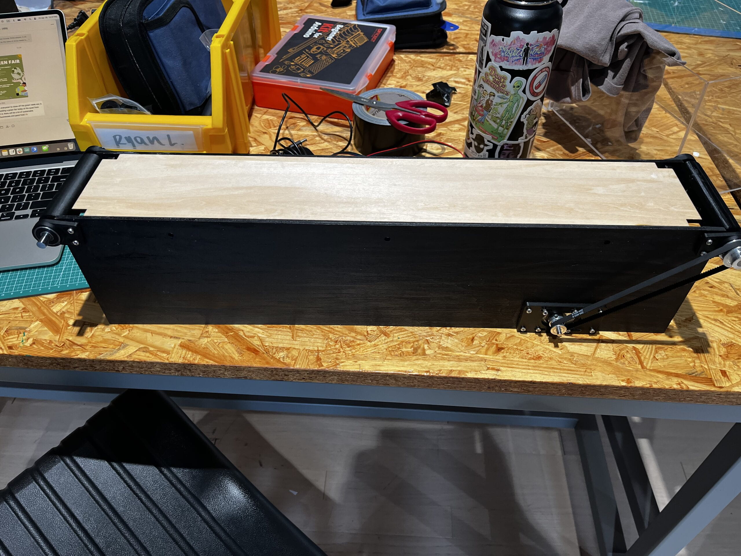
The classic design of the wooden labyrinth game is a box with a maze in the center suspended on two axes. One axis allows the maze to be titled horizontally while the other tilts it vertically. To elevate this design, I used two servo motors to control the movement of the maze. Since the classic design has two knobs on the sides of the box, I decided to have potentiometers control the servo motors, but I designed the structure so that the potentiometers would be embedded in a slanted front piece, reminiscent of an old arcade console.
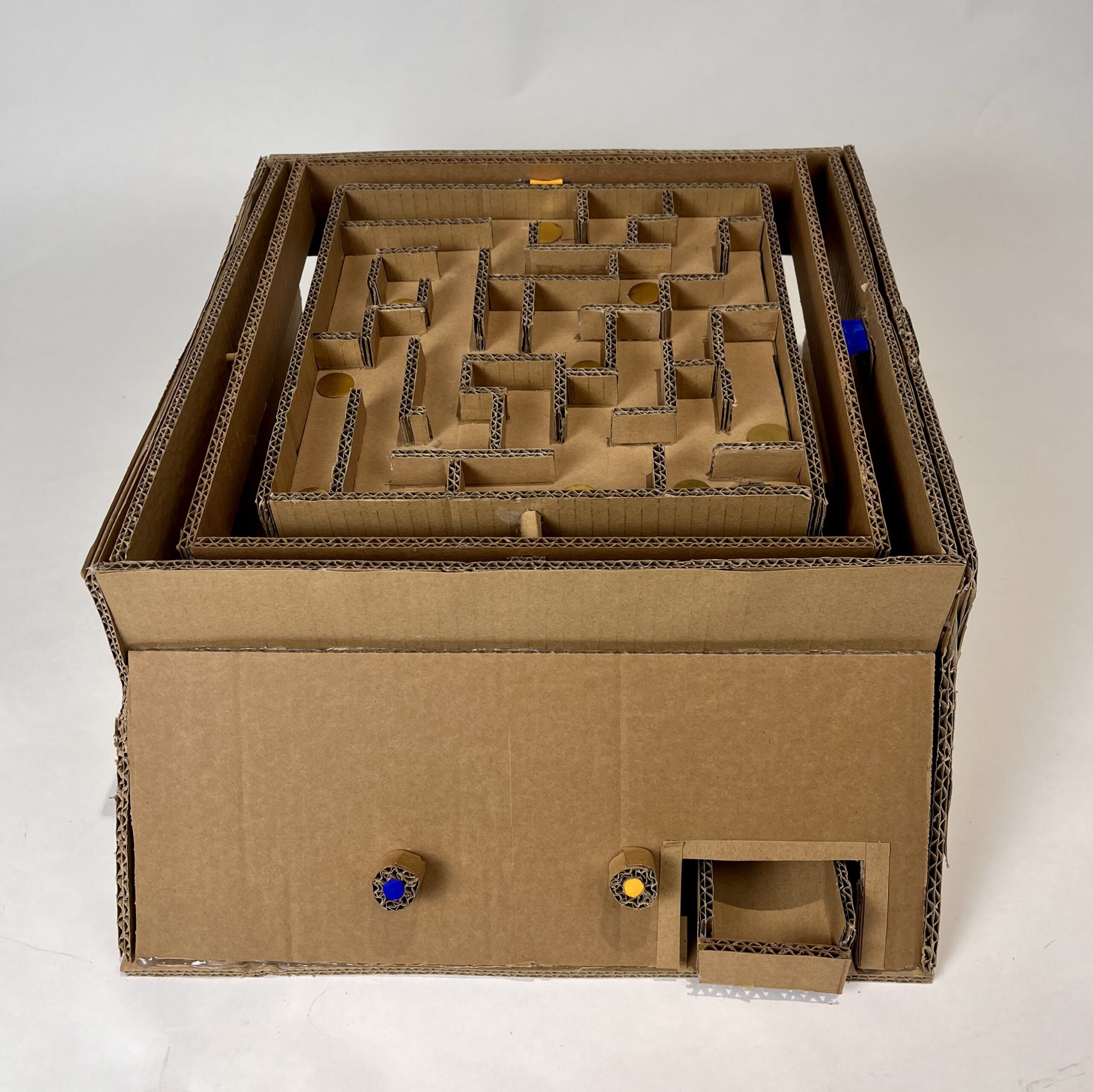
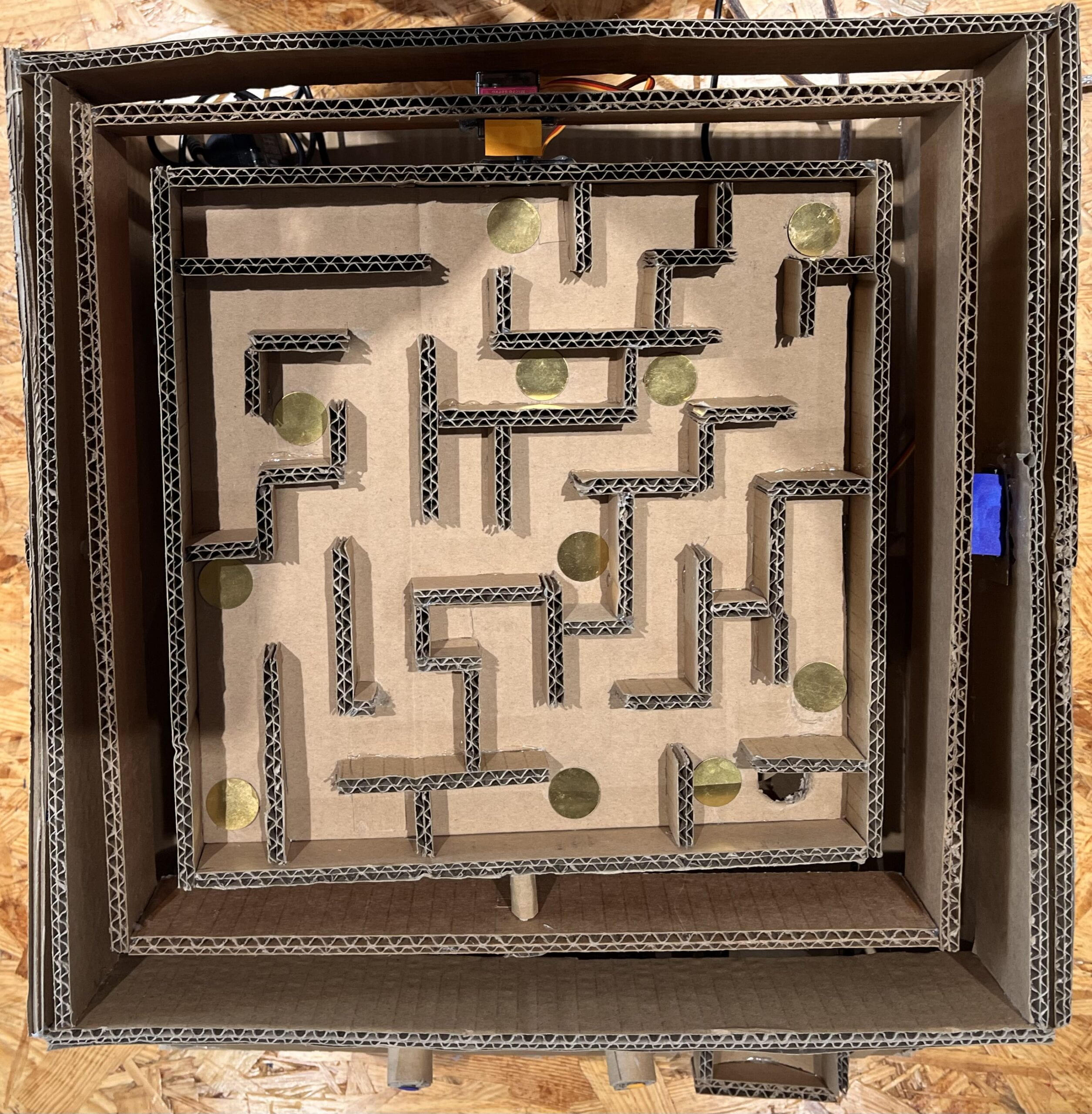
Additionally, to add an extra element to the labyrinth, I decided to use sensors throughout the maze in place of what would traditionally be holes. I wanted to make a callback to the game Operation in which touching metal edges triggers a buzzing sound and the flash of a red light. I planned to have the sensors act in the same way: when the marble moves over a sensor, the buzzer sounds, and the red LED comes on.
iii. Fabrication and Production
The first step I took in the production of this project was testing different sensors to see which would work best in the maze. I initially decided to use a capacitive touch sensor and built the maze with copper tape and the touch sensor attached, but when I went to test the finished maze, the sensor didn’t work. So, I removed the copper tape from the maze and replaced the previous spots with vibration sensors. I then built the rest of the structure with the two servos. I was not able to add the LEDs that I planned for in my design because I needed to make sure that I finished the rest of the project before I got to those since they were more decorative that the rest of the elements.
During user testing, my structure completely fell apart because I did not properly support the servos with the cardboard structure. I also initially used the blue servos, but I learned that they are less reliable than the black servos. So, learning from my mistakes, the next structure had the servos built into the cardboard. I also used black servos instead of blue ones for my final iteration.
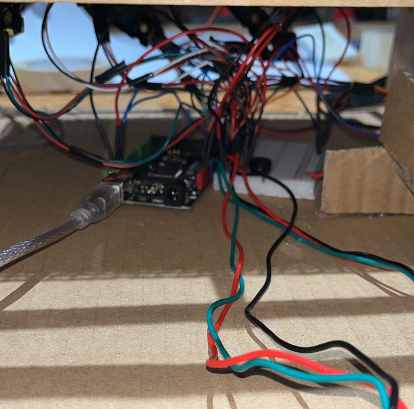
To my surprise, creating the code was the easiest step in producing this project. I simply used some of the built-in Arduino example sketches and modified them to work with my project.
iV. Conclusions
The main goal of my project was to create something fun to interact with, and after seeing the audience’s reaction to my project when I presented it, I think that goal was achieved. The whole audience was invested in seeing the player win which is exactly what I hoped for. However, if I had more time, I would make some changes. I would put in a red LED to make a stronger connection to the game Operation as I planned and place another sensor at the end of the maze that would trigger a celebratory song and a green LED to turn on. I would also try to improve the code to make the servos run more smoothly. Overall, I’m very proud of what I accomplished with Operation Labyrinth.
v. Disassembly
My project was not fully disassembled because I wanted to keep the option open to submit this project in the Interaction Lab showcase at the end of the semester. However, I returned the Arduino Mega to the Equipment Lab, and the power supply and extra servos I borrowed to the equipment cart. The eleven vibration sensors and two servos in the structure of my project are still there.
vi. Appendix
1. Extra Video Footage:
2. Code:
#include <Servo.h>

//code adapted from the Servo Knob and AnalogReadSerial Arduino Examples

Servo myservo1; //servo#1
Servo myservo2; //servo#2 int potVal1; //potentiometer#1
int potVal2; //potentiometer#2

int sensorVal1;
int sensorVal2;
int sensorVal3;
int sensorVal4;
int sensorVal5;
int sensorVal6;
int sensorVal7;
int sensorVal8;
int sensorVal9;
int sensorVal10;
int sensorVal11;


void setup() {
  Serial.begin(9600);
  pinMode(sensorVal1, INPUT);
  pinMode(sensorVal2, INPUT);
  pinMode(sensorVal3, INPUT);
  pinMode(sensorVal4, INPUT);
  pinMode(sensorVal5, INPUT);
  pinMode(sensorVal6, INPUT);
  pinMode(sensorVal7, INPUT);
  pinMode(sensorVal8, INPUT);
  pinMode(sensorVal9, INPUT);
  pinMode(sensorVal10, INPUT);
  pinMode(sensorVal11, INPUT);
  myservo1.attach(9);
  myservo2.attach(8);
  Serial.begin(9600);
}

void loop() {
  int sensorVal1 = analogRead(A2);
  if (sensorVal1 > 20) {
    Serial.println(sensorVal1);
    delay(10);
    tone(11, 600);  // plays 440 Hz on pin 11
    delay(250);
  } else {
    Serial.println(sensorVal1);
    delay(10);
    noTone(11);
  }
  int sensorVal2 = analogRead(A3);
  if (sensorVal2 > 20) {
    Serial.println(sensorVal2);
    delay(10);
    tone(11, 600);  // plays 440 Hz on pin 11
    delay(250);
  } else {
    Serial.println(sensorVal2);
    delay(10);
    noTone(11);
  }
  int sensorVal3 = analogRead(A4);
  if (sensorVal3 > 20) {
    Serial.println(sensorVal3);
    delay(10);
    tone(11, 600);  // plays 440 Hz on pin 11
    delay(250);
  } else {
    Serial.println(sensorVal3);
    delay(10);
    noTone(11);
  }
  int sensorVal4 = analogRead(A5);
  if (sensorVal4 > 20) {
    Serial.println(sensorVal4);
    delay(10);
    tone(11, 600);  // plays 440 Hz on pin 11
    delay(250);
  } else {
    Serial.println(sensorVal4);
    delay(10);
    noTone(11);
  }
  int sensorVal5 = analogRead(A6);
  if (sensorVal5 > 20) {
    Serial.println(sensorVal5);
    delay(10);
    tone(11, 600);  // plays 440 Hz on pin 11
    delay(250);
  } else {
    Serial.println(sensorVal5);
    delay(10);
    noTone(11);
  }
  int sensorVal6 = analogRead(A7);
  if (sensorVal6 > 20) {
    Serial.println(sensorVal6);
    delay(10);
    tone(11, 600);  // plays 440 Hz on pin 11
    delay(250);
  } else {
    Serial.println(sensorVal6);
    delay(10);
    noTone(11);
  }
  int sensorVal7 = analogRead(A8);
  if (sensorVal7 > 20) {
    Serial.println(sensorVal7);
    delay(10);
    tone(11, 600);  // plays 440 Hz on pin 11
    delay(250);
  } else {
    Serial.println(sensorVal7);
    delay(10);
    noTone(11);
  }
  int sensorVal8 = analogRead(A9);
  if (sensorVal8 > 20) {
    Serial.println(sensorVal8);
    delay(10);
    tone(11, 600);  // plays 440 Hz on pin 11
    delay(250);
  } else {
    Serial.println(sensorVal8);
    delay(10);
    noTone(11);
  }
    int sensorVal9 = analogRead(A10);
  if (sensorVal9 > 20) {
    Serial.println(sensorVal9);
    delay(10);
    tone(11, 600);  // plays 440 Hz on pin 11
    delay(250);
  } else {
    Serial.println(sensorVal9);
    delay(10);
    noTone(11);
  }
    int sensorVal10 = analogRead(A11);
  if (sensorVal10 > 20) {
    Serial.println(sensorVal8);
    delay(10);
    tone(11, 600);  // plays 440 Hz on pin 11
    delay(250);
  } else {
    Serial.println(sensorVal10);
    delay(10);
    noTone(11);
  }
      int sensorVal11 = analogRead(A12);
  if (sensorVal11 > 20) {
    Serial.println(sensorVal11);
    delay(10);
    tone(11, 600);  // plays 440 Hz on pin 11
    delay(250);
  } else {
    Serial.println(sensorVal11);
    delay(10);
    noTone(11);
  }
  potVal1 = analogRead(A0);
  potVal1 = map(potVal1, 0, 1023, 0, 180);
  potVal2 = analogRead(A1);
  potVal2 = map(potVal2, 0, 1023, 0, 180);
  myservo1.write(potVal1); //potentiometer#1 controls the movement of servo#1
  myservo2.write(potVal2); //potentiometer#2 controls the movement of servo#2
  Serial.println(potVal1);
  delay(20);
}