FORMULATION
An expression is formulated to determine the equivalent area, Ao, of the rigid frame in a manner similar to the method used in structures to approximate a built-up column by a homogeneous column.
Below is an approximate story drift of low-rise RFERS when H/L≤5 (where TMs is the lateral deflection calculated for the i’th story from the top (i =0 at the top); A0 is the equivalent area; Ic and lc are the inertia and height of the individual columns; Ib and lb are the inertia and length of the individual beams; b and s are the total number of bays and stories in the frame; G is the shear modulus; and W is the total acting lateral force).
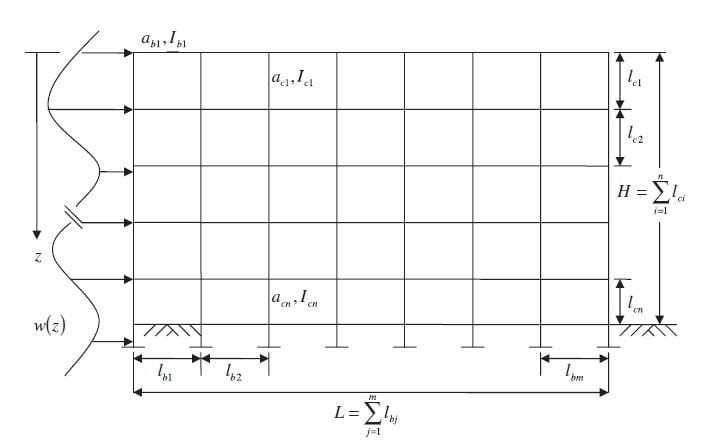
Figure 1. Legend for stories, bays, and beam and column attributes of rigidly frames structure
Numerical parametric modeling 2.3. of loading condition
Numerical parametric studies using finite element analysiswere conducted to provide data to calibrate the expressions derived in Equation and test their accuracy. Lateral deflections were obtained by performing FEM analyses, using StaadPro, on 28 000 different frame and load combinations in order to calibrate the derived expression. The modeled RFERS have a varying amount of stories, bays, size, and location of the columns and beams as shown in Figure 1. Eight of the ten parameters were varied while themodulus of elasticity, E =3150ksi and Poisson’s ratio ν=0.17 were held constant at values suitable for concrete.
RFERS varying from one to five stories and from one to ten bays were analyzed. Three combinations of column height and beam length and 25 combinations of themoments of inertia were analyzed. Two different values of total applied earth load,W, were analyzed for each of the four pressure distributions and the unknown pressure distribution. Three different combinations of column height and beam length and 25 different combinations of the moment of inertias of the beams and columns were analyzed. Finally, 14 000 additional load frame combinations were analyzed in order to verify the principal of superposition for the derived expressions. Lateral deflections were determined from the FEM analysis at every storey level of every analyzed frame, resulting in 120 000 data sets.
Calibration factors for derived equations
Multivariable non-linear regression analysis (MNRA) was performed to calibrate Equation below
using the regression analysis software DataFit Software. In MNRA, best-fit parameters for a model were obtained by minimizing the difference between all 120 000 lateral frame deflections calculated using Equation below (model), and those obtained using FEM (data).
Figure 2. Approximate story drift of low-rise RFERS when H/L ≤5 (where TMs is the lateral deflection calculated for the i’th story from the top (i =0 at the top); A0 is the equivalent area; Ic and lc are the inertia and height of the individual columns; Ib and lb are the inertia and length of the individual beams; b and s are the total number of bays and stories in the frame; G is the shear modulus; and W is the total acting lateral force).
 Primary references
Iskander, M. (2013). Relationship between temperature and earth pressure for a rigidly framed earth retaining structure. Journal of Geotechnical and Geological Engineering, Vol. 31, No. 2, pp. 519-539, doi: 10.1007/s10706- 012-9606-2, Springer [link]
Iskander, M., A. Dimond, W. Aboumoussa, and F. Masood (2012). Approximate deflection of rigidly framed earth retaining structures due to an unknown earth pressure distribution. International Journal for Numerical and Analytical Methods in Geomechanics, Vol. 36, pp. 517–532, doi: 10.1002/nag.1025, Wiley [link]


