Step 1: Build the circuit
As soon as we got to know that this was group work and we only have to make one final project in pairs, we arrived at the decision that I can work on step one, the circuit part, while my partner Nicole can work on step two, the cardboard part.
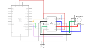
This was a challenge to me, as there were so many cables I had to connect, but the very first challenge that came to me was the question of how to connect the H-bridge to the breadboard. I thought about putting it randomly on the breadboard, but it doesn’t feel right. I wanted to figure it out by myself, but this was the very first step and without knowing the correct way to connect it to the breadboard, I could not do anything that follows. And also out of the limited time in class, I raised my hand for help and Iris came. She first asked me how I wanted to place the H-bridge and I showed her by putting two of the legs in a row, so she said by doing it that way, it will cause a shortcut with two legs in a row. And when she showed me the correct way of connection, it suddenly came to me that “That’s why is called a BRIDGE!” And it suddenly makes sense to me when I compare it with the button which also crosses the middle gap of the breadboard.
After connecting all the “colorful cables” and the 5V power from Arduino to the power line on the breadboard and then to different ports on the H-bridge, I found the black lines in the schematic diagram quite confusing, as they split at one point or either converge into one as they meet. I was quite afraid of shortcuts as they can be both damaging to me and my computer, so I then asked Professor Minsky for help by asking “What do the black lines here mean? Does it mean I can connect Arduino ground to either this port or that port? Or do I have to connect both of them to the ground?” And she patiently answered the question, and the answer was I have to connect both of them to the ground. And why so? Because these certain places need an outflow of electricity, just as some places need power in. This explanation solved the puzzle in my mind and that’s why I can still remember it clearly. And then she introduced me to her preferred way of connecting Arduino ground to the ground line on the breadboard, which conforms with what she always does in class and is truly clearer to see and debug if necessary. So I followed her suggestion and I quickly finished the circuit-building part, or at least I thought I did.
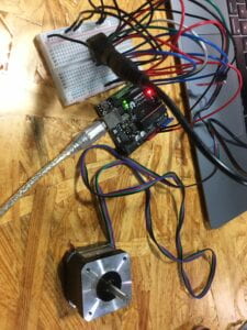
Sadly enough, I simply didn’t and what followed was even more challenging. When I uploaded the code onto Arduino, the DC motor starts to vibrate. Not having seen what it looks like when it rotates, I thought that vibration was a sign of it working normally. But then I checked the recitation page which says that it should only rotate once and then stop. And that was when I realized that there was something wrong with it, so I quickly pulled one of the cables that connects to the ground in case something dangerous and terrible happens. I looked at Lydia helplessly and she came and told me there was absolutely something wrong with my circuit and I should not use the 12V power until I finish debugging. And in my mind, debugging is always the hardest and most challenging part of all. I searched through the cables and compared my circuit to the schematic diagram several times and still got nothing. I have to say this recitation is the one during which I have asked for help the most frequently ever. I again raised my hand and Iris patiently came to my side and decided to solve the problem with me. She first confirmed if I connected every cable right, and then tried to question if the H-bridge is defective by handing me a new one. And it turned out that the DC motor was still vibrating, so the problem must be my circuit building. Indeed, she carefully found out that one of the ports of the H-bridge was empty and the cable missing is actually the one that I pugged off in fear of explosion or other dangers. Once I connected that cable, the DC motor starts to rotate. Yay! As I plugged in the 12V power, it rotates more powerfully.
Step 2: Build a cardboard mechanism!
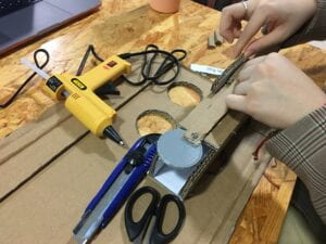 photo of Nicole cutting the cardboard
Step 3: Personalize it
Nicole drew a smiley face and cut it out from the cardboard! 🙂 Below is a video of the smiley face going up and down. 😛
Q1: Choose an art installation mentioned in the reading ART + Science NOW, Stephen Wilson (Kinetics chapter). Post your thoughts about it and make a comparison with the work you did during this recitation. How do you think that the artist selected those specific actuators for his project?
I will choose Matt Heckert’s Centripetal Sound machines (2004). I think we’re both using DC motors as actuators, but we used it almost directly-only through a rotating link to accomplish the actual control of movement. However, this piece of artwork used a handle on the DC motor and then added a string to connect it with the ring, so that the tilting of the ring can thus make the central pipe tilt from one side to another in a circular track, and also resulting in the causal movement of some other metal parts. This makes the art piece more interactive in a way that doesn’t involve humans. I think the artist first came up with the idea of making something rotate with the metal sound it creates during the rotation. And then he thinks about how he can make the ring rotate. Then he probably thought “Aha, I can make it happen by pulling one tip of it with a string up and down.” Finally, he figures out that the DC motor can rotate up and down in the way just as desired. That was how the artist selected the DC motor, I suppose.
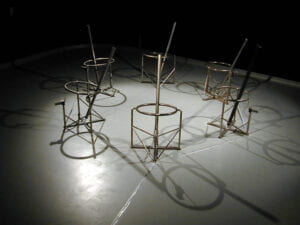
photo: http://www.mattheckert.com/sdsu.htm &video
Q2: What kind of mechanism would you be interested in building for your midterm project? Explain your idea using a sketch (conceptual or technical) with a list of materials that you plan to use. Include details about the ways that you expect the user to embrace in a physical interaction with your project. In particular, explain how would your motor (or motors) with a mechanism will be different than using an animation on a digital screen.
I would be interested in using a servo motor in building my midterm project.
Sketch: 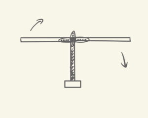
The way I expect the user to embrace in a physical interaction with this particular project is similar to that of Matt Heckert in that we both expect users to be immersed in the sound created by it (when the lever rotates and hits the floor). However, when using an animation on a digital screen, the lever cannot make a sound when it hits the “floor” because it is out from the physical environment that has “floor”. Although it may move more smoothly and also the lever may be of finer craft on the digital screen, it can be hard to reach that “immersive” kind of experience even with the same hitting sound, and it can never be the exact same thing as the physical one, which is the original one the designer creates.
