Step 1: Design
I teamed up with Nicole and I was in the role of Student A, which designs the lower part of the kinetic pattern.
I started by creating a new document and activating the “Grid snapping” option in the toolbar at the top of my canvas. But I feel like sometimes it’s still hard to place the components accurately on the grid.

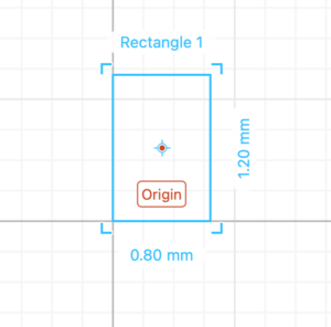
Then, I dragged a rectangle out and here the default setting of the size of the rectangle is in fact extremely small and I didn’t realize that at that time, and somehow I created a rectangle that is 0.8 mm in width and 1.2 mm in height and that’s why I couldn’t find it when I finished drawing the other rectangle.
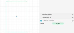
And when I was rounding the corners, I thought I added a 3 mm radius rounded corner, but at that time I still didn’t realize I was adding a 0.03 mm radius rounded corner, and the reason I did that was only because that looks more like how it looks on the example.
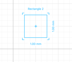
Finally, when I was drawing the other rectangle, this time, I was following the exact same parameters according to the screenshot in the instructions, the problem finally arises: I couldn’t even see where my first rectangle was! And so I then asked Professor Gottfried for help, and as he carefully checked the size of the two rectangles, he pointed out that when I zoom out, I can see the first rectangle was extremely small in the corner.
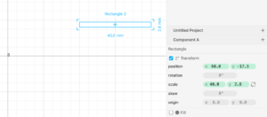
After that, things went pretty smoothly as I used the boolean difference and drew a rectangle based on the width and height of the servo measured by my partner Nicole, and positioned it at Y -100 mm. And I feel like the “placing in the middle” function was a really useful function to use.
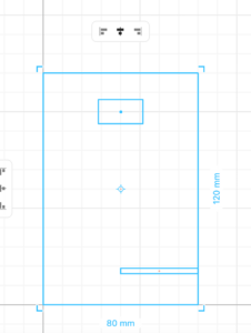
Then, when I was drawing the circle, I met some new challenges:). I dragged and dropped a circle based on the servo’s screw hole diameter. And put the radius of the circle in the “scale”. When I was adjusting the position of the circle, then comes the question of how I can make the side of the circle exactly 0.1 mm as measured close to the rectangle in the middle, so I asked Sylvia if it is not possible for the program to do it and if doing math is the only choice I have. And thanks to Sylvia, I don’t have to do the math! And there is another option, which is to zoom in and check out the more accurate “ruler” on the top of the page so that in this case, I can know that two boxes is 0.5 mm, and I can simply just count the boxes instead!
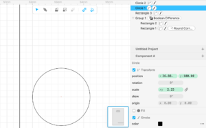
I think the main problem of the whole process was that even though I’ve watched the tutorial already, I’m still not familiar with cuttle. Moreover, I didn’t even know what we were drawing until I was in 823 and saw the stand made for us all beforehand. And honestly, that was a great relief to me because there is a large possibility that we’ve measured something wrong or drawn something wrong as we did not know what we were doing at that time.
Step 1.2: Pattern design
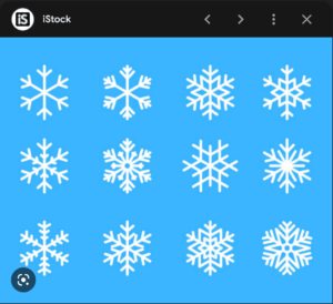
For the choice of the pattern, we decided we were going to draw a snowflake as Christmas was near! Although we missed out from the fun and opportunity to use the “pen” to create a curve and thus the failure to meet the requirement to “design patterns going in opposite directions”, as the snowflake is all composed of straight lines from this pick of a snowflake, it did save us a lot of time to draw it and compensate for the time lost at the very beginning.
I then searched for an image of a snowflake on google and we decided that we can draw a snowflake similar to the fourth one in the first row in THIS image:
We didn’t actually keep in mind the following commands, but we found we just had to use them when we want to draw something symmetrical:
- Create a shape (try using 1 or multiple paths) ->
- Rotational repeat (the more repetition the better the effect) ->
- Outline stroke ->
- Select pattern, right-click, and Group (to make it easier to move around)
And in this process, we found that it was extremely important to be accurate to place the corners on the grid; otherwise, some lines will just be pointing out somewhere and then if we increase the stroke weight, it will be more obvious.
Also, although we didn’t have curves to create an interesting effect through the opposite directions, what we did instead was to make the lines stagger. While Nicole was first drawing a line on the y-axis and then rotating it three times, I was drawing a line on the x-axis. But when I think about that now, it is probably unnecessary, for the position may matter for the piece behind, as the rectangle I drew for the potentiometer to go through does determines the position of it, the position of the piece in the front can be changed when we assemble it as it is only going through a hole, and a circle is symmetrical from any direction.
Step 1.3: Export your design
Upon finishing the drawing, we showed the pattern to Iris to check if we’re good to go on to laser cutting and as she approved, we saved the file and exported in an SVG format. Then, we created a new folder with our names in the Google Drive and add both of our files.
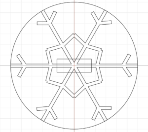 My pattern
Step 2: Laser cut
When we were about to laser cut out pattern, Andy corrected my pattern by adding a frame to the rectangle in the middle, so that the sticks wouldn’t be sticking to nowhere, but be attached to a frame instead. Thanks to Andy, our snowflake escaped from being fragile and looking strange. And that part I wouldn’t even think about that without his remind and also I would have no idea how to fix that either.
Step 3: Assemble
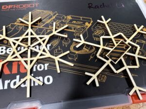
Here are the two pieces of designs cut out and we then assembled them together:
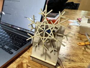
Then, we connected the servo wires to your Arduino with the servo sweep example and here is the code and the video:
/* Sweep
 by BARRAGAN <http://barraganstudio.com>
 This example code is in the public domain.

 modified 8 Nov 2013
 by Scott Fitzgerald
 https://www.arduino.cc/en/Tutorial/LibraryExamples/Sweep
*/

#include <Servo.h>

Servo myservo;  // create servo object to control a servo
// twelve servo objects can be created on most boards

int pos = 0;    // variable to store the servo position

void setup() {
  myservo.attach(9);  // attaches the servo on pin 9 to the servo object
}

void loop() {
  for (pos = 0; pos <= 180; pos += 1) { // goes from 0 degrees to 180 degrees
    // in steps of 1 degree
    myservo.write(pos);              // tell servo to go to position in variable 'pos'
    delay(15);                       // waits 15 ms for the servo to reach the position
  }
  for (pos = 180; pos >= 0; pos -= 1) { // goes from 180 degrees to 0 degrees
    myservo.write(pos);              // tell servo to go to position in variable 'pos'
    delay(15);                       // waits 15 ms for the servo to reach the position
  }
}
