Circuit 1: Fade
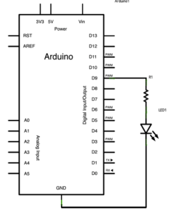
That was the first day we got our own Arduino kit, and when I connected Arduino uno with the USB-C adapter and the cable to my computer and opened Arduino IDE, I clicked on the search box which says “select board” and found that it was different from what I usually see when using the one which is delivered on class. So I asked for help and then I learned to search for Arduino uno and select the USB port to get it connected, and everything then worked out!
Circuit 2: toneMelody
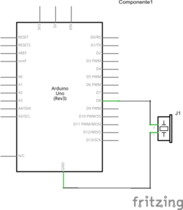 When I was going to connect the buzzer into the circuit, I almost took the other kind of cable, which looks similar but different from the jumper cable, but when I tried to plug in, I could immediately tell the differences, and it was through this process that I learned that there are actually perhaps more than one type of cables, for various possible uses.
Circuit 3: Speed Game
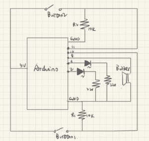 It took us a long time to finish connecting all the components together with so many cables. And at that time, I wasn’t familiar with how the electricity flows through the wires, so I had to follow the graph strictly in case I get anything wrong. Luckily, we got it all right for the first time and don’t have to do any debugging. 🙂
As I opened the serial monitor and saw it saying “Ready. Set. Go!!!!” , we started to press on the small little button as fast as we could. And the red light near me lit up, with the buzzer declaring a triumph, suggesting that I had won the first game! To test the other side, we switched sides, and I actually found out the other side was harder to press faster because it was so close to another wire. So we changed the connection of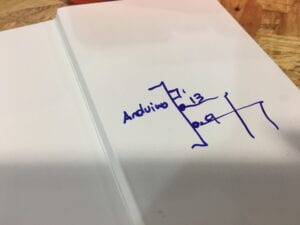 the wire and updated it into a better game player. After that update, I wondered how to draw the schematic for the circuit, as it is connected to many ports on Arduino uno. So we asked Prof. Gottfried and he patiently explained how he usually draws it and the photo on the right is an example that he drew.
Q1:
From the introduction chapter and something I found interesting in Chapter 11, I think I could use a button with a force-sensitive resistor connected to it and also a system that can create force feedback all through Microcontrollers. By doing so, I’ve changed a digital input into an analog input, which is to say, I have to use the word “stronger” rather than “whether ot not” to describe the input, which makes it more fun, interesting and therefore, more interactive. And the force feedback is kind of the same thing, where the button can “speak in different voices” to be more engaged in the whole dialogue of interaction.
Q2:
To ensure we always read LOW when the button is not pressed, we thus add a 10k Ohm resistor in a configuration known as a PULL-DOWN RESISTOR.
Q3:
I found the 5127th prototype of the vacuum cleaner made by James Dyson really interesting. (Getting Started with Arduino, 6) I think it is a great example of prototyping, because the inventor is always trying to come up with a new prototype even with the least changes to the ready-made last version. And without these first 5126 failed prototypes, such success could never have been made. I chose James Dyson’s vacuum cleaner because I think there is no perfect prototypes at the beginning of the research, and that his project, which is based on so many times of failure, is a valuable example to show what is the fastest and best way to invent something. This example really helped me understand the “Arduino way” in terms of prototyping.
 6 of the 5126 failed prototypes
