Video:
Stills:
Code:
IMA Documentation Blog
Video:
Stills:
Code:
In the first prototype, I built a simple Wi-Fi beeper that reflects the signal strength (RSSI) of each signal by connecting it to a buzzer. It was a proof of concept that the system can create an interactive experienece that shows how the environment can have an impact on the individual in an invisible and untouchable way.
Taking a step further, the goal of the second prototype is to:
This blog post will be divided in 3 parts: wiring, setting up Mozzi (2 examples), and working prototype 2.
Photo: Prototype 2 Wiring
For prototype 2, the wiring contains two potentiometers for analog input, and an additional potentiometer for volume control (together with a capacitor to smooth audio quality). These two potentiometers are connected to ESP32, which runs Mozzi. For output, a GPIO pin with Audio (DAC) capabilities is connected to the earphone. The earphone is connected using wire clamps, corresponding to each section of the 3.5mm audio jack.
In order from the inside to the outside: Microphone -> Ground -> Left -> Right
It’s a very temporary and experimental setup, which will change in the future to improve stability and cleaner connections.
An ESP8266, responsible for Wi-Fi scanning, is connected to ESP32 via analog, more specifics will be in the following sections.
In this example, two potentiometers are mapped to pitchValue (frequency) and cutoff frequency for a low-pass filter. The potentiometers can control the features of sinwave synth. This example demonstrates a basic synth which can be shaped and manipulated further.
This example utilizes bluetooth scan, trying to achieve scanning and sound production on the same board, but with little success.
The logic of the bluetooth scan is as follows:
BLEScan *scan = BLEDevice::getScan();
scan->setActiveScan(true);
BLEScanResults results = scan->start(1);
int best = CUTOFF;
for (int i = 0; i < results.getCount(); i++) {
BLEAdvertisedDevice device = results.getDevice(i);
int rssi = device.getRSSI();
if (rssi > best) {
best = rssi;
}
This code snippet will grab the “best” bluetooth signal, and countinuously return the biggest signal source and its numerial signal strength value (RSSI). In turn, the signal value (RSSI) will define an arpeggiator pattern that “should” make the sinwave synth more musical.
However, a big problem is the incompatibility of running Bluetooth/Wi-Fi on a single board, with Mozzi. Mozzi code structure includes special sections such as UpdateControl(), updateAudio(), which operates on high frequencies (~16000Hz) to match audio control rate. Adding anything related to Serial Communication, WiFi, Bluetooth, or just timing functions in general would not work with Mozzi.
Therefore, the only option left is to use another board (ESP8266) and separate the bluetooth function with the sound board, and utilize analog output/input (PWM pin) to transmit data.
This example plays a fluctuating ambient wash in response to the Wi-Fi scan results and a potentiometer. The Wi-Fi scan controls the base frequency of the oscillator, and the potentiometer controls oscillator offset depending on the resistance.
There are two sets of oscillators. The first set uses 7 different Cosine wavetables to produce a harmonic synth sound. The second set duplicates but slightly off frequency for adding to originals. There is a pre-set offset scale to map WiFi scan result to base frequency drift.
The base midi notes are: C3 E3 G3 A3 C4 E4, and translates to
The current prototype took a step further and accompolished synth generation with Wi-Fi inputs. For the next prototype, the goal is to build a more defined user experience. Achiving that requires a re-thinking of the input variables that the system uses (currently is the number of Wi-Fi signals detected). Adding temperature, light, or other inputs might complicate things further and generate richer sound. However, that requires a deeper and higher level understanding of Mozzi, especially how to change synths parameters and control sounds.
The overarching theme of this project is the mix between digital and human features. Specifically, how the environment can have an impact on the individual in an invisible and untouchable way.
Inspired by the Bluetooth Visualizer and the Ambient Machine, I want to create a sound machine that reacts to radio signals (Wi-Fi signals as the primary option to recieve signals).
The goal for the first prototype is to test how to detect Wi-Fi and make sounds accordingly. This process is based on an ESP32 chip, and developed in Arduino IDE.
First, I explored how to detect Wi-Fi signals on an ESP32 board, using the Wi-Fi Scan example.
In this example, the ESP32 board can get:
I am using RSSI (signal strength) in this prototype as the main input. The output is a simple buzzer that makes sound based on signal strength. I defined a couple of notes and their frequencies, and higher the signal strength, higher the pitch. The notes and pitch are defined as follows:
The code works as follows: the ESP32 loops through all the wifi signal that it detects, the buzzer will beep according to the signal strength. For example, if there are 3 wifi networks, signal strength are -80, -70, -60 respectively, then the buzzer will beep notes E, F, G.
The benefits of the ESP32 is portability. To demonstrate, I connected the ESP32 board to a power bank (thanks Prof de Bel for the power bank) and walked around the campus. I found that there are more wifis in the courtyard than actually inside the building (because the beeping sequence was longer). Here’s a video demo:
Overall, this simple prototype demonstrates that the basic idea works. Wi-Fi detection is feasible and easy to implement. However, in the next step, making pleasant sound is much harder. Music coding platform SuperCollider is very hard to manage. So I will try to use other ways (synthesizers) or adding effects to construct ambient sounds.
FULL CODE
This immersion experience is conducted in the Taikoo Li mall 2F (stone zone). The immersion is comprised of 3 part:
and this post documents the observe phase and interact phase. To avoid people staring at me since the immersion time lasted around 1 hour, and also implement the process more effectively, I adopted 3 items from the Oblique Strategies by Brian Eno and Peter Schmidt:
Here are the results:
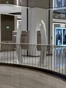
The map machine is located around the main entrance of each floor, with a industrial but modern look and design.
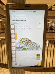
The map has a default view, with an overall map of the entire mall. Unfortunately, there were no markings, serial numbers, or indication of where it was made. The machine is housed by a metallic case, which makes it hard to probe its insides.
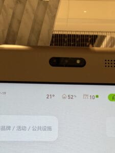
Immdiately, a camara mounted on the top of the machine is very visible. There were no applications in the machine that explicitly uses the camara, which left me wonder what it actually does (facial recognition? consumer portraits?)
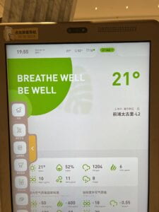
A very detailed air quality dashboard.
When I touched the screen, the bubble upon touch resembles an android system.
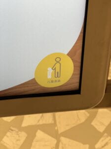
Height friendly mode that changes the screen size.
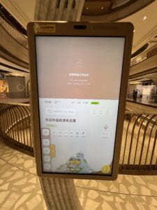
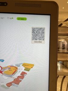
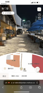
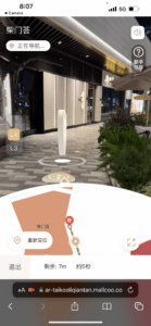
Finally, a very interesting AR navigation experiment. Scan a QR code, login on the phone, then the AR app will take you to your destination. But it is awkward because you need to hold the phone high and aim at the road in front of you.
The Ice Cream Machine Visit: The interaction (see the interaction illustration below)
The interaction between human and the ice cream machine starts with the customer selecting and paying for the ice cream, which the process is operated on a screen and a computer. Then, the computer sends instructions to a robotic arm which it will perform a set sequence of making the ice cream and delivering it to the customer.
In the entire process, no human is involved except for the customer. But for maintainance, there has to be someone to fill up the supplies, such as milk and the cones.
The content on the screen is pretty simple: a button to start ordering, a payment system based on WeChat or Alipay, and then a finishing up animation.
In terms of sounds, it was very interesting that no computer-generated sounds were used at all. For the robotic arm, it makes basically no sounds, so the experience is mostly visual and psysical.
The first eye-catching and most obvious theme is the visualization of the “invisible links” of smart cities, which could represent the internet, data transfers, or something else.
The second theme common is a background picture of a highly developed city, typically at night, emphasizing the use of electricity as a manifestation of development.
The third themes is a futuristic, or even cyberpunk, interpretation of the smart city.
These themes are a symbolic representation of some of the characteristics of the smart city. They give people a feeling that smart cities are inadvertently linked to high-tech, the internet, highly-developed big metropolises.
The shared bikes! Shared umbrellas sometimes too. Waimai (delivery services).
The benefits are mostly convenience to commute (especially when the distance traveled is shorter than a taxi ride but too long for walking), and the fact that you can use the services by just having a phone. The frustration is that the placement of bikes are mostly random, and at peak times you cannot find a bike home.
I find that Constant’s idea of “the nomadic life of creative play” a very interesting concept. There are many ways to play in the city, and I think Constant meant creating a life of leisure inside the city, which could include things like going to the movies, a bar, or taking a walk in a park.
Technology could enhance play mainly by automation and awareness. The author of the article mentioned that “Spaces in New Babylon would somehow need to be ‘aware’ of the activities taking place in them so that the environment could know when to change its appearance and behavior.” The ambient environment and its automation enhances the experience of many leisure activities, but not to the extend that Constant may have envisioned.
Lastly, diversity represents a significant factor in the making of a smart city. To quote from the article, “the smartness comes from the diverse human bodies of different genders, cultures, and classes whose rich, complex, and even fragile identities ultimately make the city what it is.” It’s the engagement and blending of people from different backgrounds that matters more than just the technology or the profit stream of companies.
A. Submarine – Peirong Li – Professor Gottfried Haider
(Image: game logo)
B. CONCEPTION AND DESIGN
This project is an arcade-like game in which an idiosyncratic control panel (a wheel) is used to steer the submarine to descend in the ocean. My definition of interaction is “an intuitive set of actions that occurs between systems (non-human) and participants (human), in which both the system and the participants are equally involved, through facilitated or ambient physical elements that invite responses in a continuous loop.” My project aims to align with this definition by creating a system that reacts but responds directly to audience action.
At the beginning of this project, a key design decision was to use the rotary encoder as the main sensor and input instrument. This decision is the foundation of making a smooth experience for the game. On the graphic side of things, I used Processing to create a virtual world. The main mechanism is using a long image scrolling up to give the user a feeling that the game is progressing downwards. Techniques such as pixel color detection were used to detect collisions and also detect the “bufferzone”, which sends a vibration signal whenever the user gets too close to the border. During the earlier phase of the project, I used a simple, small wheel for control. User testing feedback gave me the idea to have a much bigger wheel to allow the user more movement and make the game experience more physical and amplified. Importantly, I also came up with the idea of a “secondary control”, in which the rest of the screen is black, and a second wheel controls the “lighting”, to make the game harder and more interesting.
C. FABRICATION AND PRODUCTION
Before User Testing:
1. Fabrication & Arduino
The very first thing I did was try out the rotary encoder and write the code to make sure that this main sensor works as expected. After a few unsuccessful tries, Professor Haider provided some very helpful guidance on using the “interrupt” method in Arduino to count how fast the wheel is turning, and which direction it is turning. Next, I fitted the rotary encoder to a laser-cut box and installed a small wheel that I purchased online and modified.
(image: rotary encoder with the small wheel)
(image: pre-user testing package fitted iside a wood box)
(video: testing with a circle )
2. Processing
After the physical mechanism was working, I turned to Processing.
(image: the submarine logo used in the game)
At first, I used Adobe Firefly, a text-to-image generative platform, to generate some concept art. I started out from the overall code structure that has an initial screen, a game screen, and a game over screen. The main game asset is a long png image that includes rocks on the side, a bright yellow line that the user needs to avoid, and deep blue background. I also used Adobe Firefly to generate “rocks” and incorporated them into game assets. Collision detection is based on pixel detection. Whenever the pixel at the edge of the submarine is yellow, which is also the color of the borderline, the game ends. At this stage of development, the game was still very short and not integrated.
The game asset were drew using Procreate and Adobe Photoshop.
(image: the main game asset)
(video: user testing session)
After User Testing:
1. Fabrication & Arduino
The most important feedback from User Testing was to make the experience more physical and increase the size of the installation. I purchased a wooden wheel, some bearings (ended up not using these), and some lightstrips for decoration from online platforms. I picked some leftover wooden panel and sticks, and with help from Professor Garcia, I fitted the rotary encoder to a standing wooden stick and installed the wheel on the encoder. Then, I decided to utilize the previous small box/wheel to set up a secondary control to manipulate the “lighting” function. Arduino code was altered accordingly to accommodate two rotary encoders, which was the maximum number of encoders that could be connected to the Arduino Uno board. Moreover, for decorative purposes, I did three things to improve the overall design: 1) a big laser-cut wood box behind the wheel to house all the cables and Arduino board, and also acts as a computer stand; 2) two buttons for starting the game and returning to menu; 3) light strips installed on the side of the base platform to improve aesthetics; 4) a vibration motor that reacts when the user is too close to the edge.
(image: the big wheel)
(image: final look)
(image: final look from another angle)
2. Processing
There were major extensions on the Processing side as well. First of all, the main game asset was extended 5 times longer, and a second level was added, making the game experience around 3 minutes long. Two screens were added, a “ScreenB” for the second level, and an “end screen” for users that completed the game. I used Framerate() to control the speed of the game, and found that 120 frames was the best setting for users to play at. An extremely important modification was to call the resize function during setup() instead of draw(), and this drastically improved efficiency and saved the game from lagging severely. Button presses and vibration signals through serial communication were also added. For the second level, I added a method called “masking”, in which the loadPixels() function was used to scan the screen pixel by pixel and black out the entire screen except a circle controlled by the user using the same mechanism as the wheel. Finally, a reset() function was added to re-initialize all the global variables to their original values when the blue (return to main menu) button was pressed.
(image: the final main asset)
D. CONCLUSIONS
The goal of this project is to create an interactive experience that involves the installation and the user equally, in the form of a game that utilizes actuators and sensors. The audience interacted with the project just as expected, since the control mechanism was very self-explanatory. I believe that the project aligns with my definition of interaction. There are many considerable improvements can be made if there are more time, for example: adding sounds and music, with beeps going off when the user is close to the edge, complementing the vibration motor; fitting the vibration motor to the wheel; fabricating a single button mechanism that is more intuitive for navigating the menus; fabricating a wood panel that resembles a “submarine window” and fit the screen behind it; add floating things to make the game environment more vibrant; using alpha values for collision detection instead of color; clearer instructions, etc. Overall, I believe this project is a success. There were many setbacks and difficulties that I encountered during the process, but each time when I resolved it, I gained from it and my problem-solving skills improved. Just as Professor Haider said, “programming (and electronics) is to a large degree a matter of practice,” and I learned not just fabrication or coding skills, but the ability to engage in the creative process, conceive ideas, and apply skills to make these ideas a reality.
(image: IMA show)
E. APPENDIX
Credit: Professor Gottfried Haider (Arduino Code), Professor Andy Garcia (Fabrication), Adobe Firefly (Assets)
(Video: Full Demo Video at the IMA show)
FULL CODE
Arduino
#define PIN_A 2
#define PIN_B 4
#define PIN_C 3
#define PIN_D 5

#define NUM_OF_VALUES_FROM_PROCESSING 1
/* This array stores values from Processing */
int processing_values[NUM_OF_VALUES_FROM_PROCESSING];

int delta_A = 0;
int delta_B = 0;

void setup() {
  Serial.begin(115200);
  pinMode(8, OUTPUT);
  pinMode(PIN_A, INPUT_PULLUP);
  pinMode(PIN_B, INPUT_PULLUP);
  pinMode(PIN_C, INPUT_PULLUP);
  pinMode(PIN_D, INPUT_PULLUP);
  pinMode(11,INPUT);
  pinMode(12,INPUT);
  attachInterrupt(digitalPinToInterrupt(PIN_A), shaft_moved_1, FALLING);
  attachInterrupt(digitalPinToInterrupt(PIN_C), shaft_moved_2, FALLING);
}

void loop() {

  getSerialData();
  // add your code here using incoming data in the values array
  // and print values to send to Processing

  int buttonState1 = digitalRead(12);
  int buttonState2 = digitalRead(11);

  // example of using received values and turning on an LED
  if (processing_values[0] == 1) {
    digitalWrite(8, HIGH);
  } else {
    digitalWrite(8, LOW);
  }

  int old_A = delta_A;
  delta_A = 0;
  int old_B = delta_B;
  delta_B = 0;
  Serial.print(10000 + old_A);
  Serial.print(",");
  Serial.print(10000 + old_B);
  Serial.print(",");
  Serial.print(buttonState1);
  Serial.print(",");
  Serial.println(buttonState2);
  delay(100);
}

void shaft_moved_1() {
  int pinb_value = digitalRead(PIN_B);
  if (pinb_value == HIGH) {
    delta_A = delta_A - 1;
  } else {
    delta_A = delta_A + 1;
  }
}

void shaft_moved_2() {
  int pind_value = digitalRead(PIN_D);
  if (pind_value == HIGH) {
    delta_B = delta_B - 1;
  } else {
    delta_B = delta_B + 1;
  }
}

/* Receive serial data from Processing */
/* You won't need to change this code */
void getSerialData() {
  static int tempValue = 0;
  static int valueIndex = 0;
  while (Serial.available()) {
    char c = Serial.read();
    // switch - case checks the value of the variable in the switch function
    // in this case, the char c, then runs one of the cases that fit the value of the variable
    // for more information, visit the reference page: https://www.arduino.cc/en/Reference/SwitchCase
    switch (c) {
      // if the char c from Processing is a number between 0 and 9
      case '0' ... '9':
        // save the value of char c to tempValue
        // but simultaneously rearrange the existing values saved in tempValue
        // for the digits received through char c to remain coherent
        // if this does not make sense and would like to know more, send an email to me!
        tempValue = tempValue * 10 + c - '0';
        break;
      // if the char c from Processing is a comma
      // indicating that the following values of char c is for the next element in the values array
      case ',':
        processing_values[valueIndex] = tempValue;
        // reset tempValue value
        tempValue = 0;
        // increment valuesIndex by 1
        valueIndex++;
        break;
      // if the char c from Processing is character 'n'
      // which signals that it is the end of data
      case '\n':
        // save the tempValue
        // this will b the last element in the values array
        processing_values[valueIndex] = tempValue;
        // reset tempValue and valueIndex values
        // to clear out the values array for the next round of readings from Processing
        tempValue = 0;
        valueIndex = 0;
        break;
    }
  }
}
Processing
/********* VARIABLES *********/
// 0: Initial Screen
// 1: Game Screen
// 2: Game-over Screen
// 3: Game Screen B
// 4: End Screen
import processing.serial.*;
Serial serialPort;

PImage[] images = new PImage[10];

int NUM_OF_VALUES_FROM_ARDUINO = 4;
/* This array stores values from Arduino */
int arduino_values[] = new int[NUM_OF_VALUES_FROM_ARDUINO];

int NUM_OF_VALUES_FROM_PROCESSING = 1;  /* CHANGE THIS ACCORDING TO YOUR PROJECT */
/* This array stores values you might want to send to Arduino */
int processing_values[] = new int[NUM_OF_VALUES_FROM_PROCESSING];

boolean buttonPressedRed = false;
boolean buttonPressedBlue = false;

float speedX;
float x = 250;
float accelX;

float speedX_mask;
float x_mask = 250;
float accelX_mask;
float maskSize = 250;

float title_y = -150; //title init pos
float bg_y = 0;

float portal_y = 4075+170+1909+800;
int fade_y = 4380+170+1909+800;

float bg2_y = 0;
float opacity_4 = 0;
float op1 = 0;

float boundaryLeft;   // left boundary
float boundaryRight;  // right boundary

color left_color, right_color;
float leftR, leftG, leftB;
float rightR, rightG, rightB;

int gameScreen = 0;

/********* SETUP BLOCK *********/

void setup() {
  //fullScreen();
  size(600, 900);
  frameRate(120);
  noSmooth();
  boundaryLeft = 0;             // set the left boundary
  boundaryRight = width - 100;    // set the right boundary

  printArray(Serial.list());
  serialPort = new Serial(this, "/dev/cu.usbmodem14401", 115200);

  // Load all the images into an array
  for (int i = 0; i < images.length; i++) {
    images[i] = loadImage(i + ".png");
  }
  //pre-resizing to improve performance
  images[0].resize(600, 900);
  images[1].resize(550, 0);
  images[2].resize(600, 7600);
  images[3].resize(100, 100);
  images[4].resize(400, 100);
  images[5].resize(600, 825);
  //images[6].resize(600, 5691);
  images[7].resize(600, 5691);
}


/********* DRAW BLOCK *********/

void draw() {
  if (arduino_values[2] == 1) {
    buttonPressedRed = true;
  } else {
    buttonPressedRed = false;
  }

  if (arduino_values[3] == 1) {
    buttonPressedBlue = true;
  } else {
    buttonPressedBlue = false;
  }
  // Display the contents of the current screen
  getSerialData();

  if (gameScreen == 0) {
    initScreen();
  } else if (gameScreen == 1) {
    gameScreen();
  } else if (gameScreen == 2) {
    gameOverScreen();
  } else if (gameScreen == 3) {
    gameScreenB();
  } else if (gameScreen == 4) {
    endScreen();
  }
  // send the values to Arduino
  sendSerialData();
}


/********* SCREEN CONTENTS *********/

void initScreen() {
  // codes of initial screen
  background(255);
  tint(255, 255);
  image(images[0], 0, 0);

  tint(255, op1);
  image(images[1], 25, 200);
  op1 += 2;

  if (buttonPressedRed == true) {
    if (gameScreen==0) {
      reset();
      startGame();
    }
  }
}

void gameScreen() {
  if (bg_y < -4430.0 - 1909.0 - 800.0) {
    gameScreen = 3;
  }

  // code of game screen
  image(images[2], 0, bg_y);
  bg_y -= 1;

  //submarine init
  noStroke();
  fill(243, 247, 12);
  image(images[3], x, 150);

  //x speed processing
  x = x + speedX;
  speedX = speedX + accelX;
  speedX = speedX * 0.9;
  accelX = map(abs(arduino_values[0]), 11000, 9000, -1, 1);

  //boundry setting
  if (x <= boundaryLeft || x >= boundaryRight) {
    speedX = -speedX;
    // adjust the position of the circle so that it stays within the boundary
    if (x < boundaryLeft) {
      x = boundaryLeft;
    } else if (x > boundaryRight) {
      x = boundaryRight;
    }
  }

  //collision detection, r = 50
  left_color = get(round(x)+5, 215);
  //circle(round(x),215,10);
  right_color = get(round(x)+90, 215);
  //circle(round(x)+80,215,10);

  //yellow border detection
  leftR = red(left_color);
  leftG = green(left_color);
  leftB = blue(left_color);
  rightR = red(right_color);
  rightG = green(right_color);
  rightB = blue(right_color);
  //println(leftR,leftG,leftB,"  ",rightR,rightG,rightB);
  if ((leftR > 140 && leftR < 192) && (leftG > 130 && leftG < 140) && (leftB > 48 && leftB < 60)) {
    gameScreen = 2;
  } else if ((rightR > 140 && rightR < 200) && (rightG > 128 && rightG < 142) && (rightB > 45 && rightB < 62)) {
    gameScreen = 2;
  } else if ((leftR > 7 && leftR < 40) && (leftG > 46 && leftG < 58) && (leftB > 80 && leftB < 94)) {
    processing_values[0] = 1;
  } else if ((rightR > 7 && rightR < 40) && (rightG > 46 && rightG < 58) && (rightB > 80 && rightB < 94)) {
    processing_values[0] = 1;
  } else {
    processing_values[0] = 0;
  }

  println(bg_y);
  //-4075
  image(images[9], 0, portal_y);
  portal_y -= 1;

  image(images[8], 0, fade_y);
  fade_y -= 1;
}

void gameScreenB() {
  if (bg2_y < -5540) {
    gameScreen = 4;
  }
  background(0);
  // Draw the image with an alpha value of 100
  image(images[7], 0, bg2_y);
  bg2_y -= 1;

  //submarine init
  noStroke();
  fill(243, 247, 12);
  image(images[3], x, 150);

  //x_mask speed processing
  x_mask = x_mask + speedX_mask;
  speedX_mask = speedX_mask + accelX_mask;
  speedX_mask = speedX_mask * 0.95;
  accelX_mask = map(abs(arduino_values[1]), 11000, 9000, -1, 1);

  // Masking
  loadPixels();
  for (int x1 = 0; x1 < width; x1++) {
    for (int y = 0; y < height; y++) {
      float d = dist(round(x_mask), 215, x1, y);
      if (d > maskSize/2) {
        int index = x1 + y * width;
        pixels[index] = color(0);
      }
    }
  }
  updatePixels();

  //x speed processing
  x = x + speedX;
  speedX = speedX + accelX;
  speedX = speedX * 0.95;
  accelX = map(abs(arduino_values[0]), 11000, 9000, -1, 1);

  //boundry setting
  if (x <= boundaryLeft || x >= boundaryRight) {
    speedX = -speedX;
    // adjust the position of the circle so that it stays within the boundary
    if (x < boundaryLeft) {
      x = boundaryLeft;
    } else if (x > boundaryRight) {
      x = boundaryRight;
    }
  }

  //collision detection, r = 50
  left_color = get(round(x)+5, 215);
  right_color = get(round(x)+90, 215);

  //yellow border detection
  leftR = red(left_color);
  leftG = green(left_color);
  leftB = blue(left_color);
  rightR = red(right_color);
  rightG = green(right_color);
  rightB = blue(right_color);
  if ((leftR > 140 && leftR < 192) && (leftG > 130 && leftG < 140) && (leftB > 48 && leftB < 60)) {
    gameScreen = 2;
  } else if ((rightR > 140 && rightR < 200) && (rightG > 128 && rightG < 142) && (rightB > 45 && rightB < 62)) {
    gameScreen = 2;
  } else if ((leftR > 7 && leftR < 40) && (leftG > 46 && leftG < 58) && (leftB > 80 && leftB < 94)) {
    processing_values[0] = 1;
  } else if ((rightR > 7 && rightR < 40) && (rightG > 46 && rightG < 58) && (rightB > 80 && rightB < 94)) {
    processing_values[0] = 1;
  } else {
    processing_values[0] = 0;
  }
  println(bg2_y);
}

void gameOverScreen() {
  // codes for game over screen
  background(255);
  image(images[4], 100, 420);
  tint(255, opacity_4);
  if (opacity_4 <= 255) {
    opacity_4 += 1;
  }
  if (buttonPressedBlue == true && gameScreen == 2) {
    gameScreen = 0;
  }
}

void endScreen() {
  image(images[5], 0, 0);
  if (buttonPressedBlue == true && gameScreen == 4) {
    gameScreen = 0;
  }
}

/********* INPUTS *********/

public void keyPressed() {
  // if we are on the initial screen when clicked, start the game
  /*
  if (gameScreen==0) {
   startGame();
   }
   if (key == 'b' || key == 'B') {
   gameScreen = 3;
   }
   */
}


/********* OTHER FUNCTIONS *********/
void startGame() {
  gameScreen=1;
}

void getSerialData() {
  while (serialPort.available() > 0) {
    String in = serialPort.readStringUntil( 10 );  // 10 = '\n'  Linefeed in ASCII
    if (in != null) {
      //print("From Arduino: " + in);
      String[] serialInArray = split(trim(in), ",");
      if (serialInArray.length == NUM_OF_VALUES_FROM_ARDUINO) {
        for (int i=0; i<serialInArray.length; i++) {
          arduino_values[i] = int(serialInArray[i]);
        }
      }
    }
  }
}

void sendSerialData() {
  String data = "";
  for (int i=0; i<processing_values.length; i++) {
    data += processing_values[i];
    // if i is less than the index number of the last element in the values array
    if (i < processing_values.length-1) {
      data += ",";  // add splitter character "," between each values element
    }
    // if it is the last element in the values array
    else {
      data += "\n";  // add the end of data character "n"
    }
  }
  // write to Arduino
  serialPort.write(data);
  //print("To Arduino: " + data);  // this prints to the console the values going to Arduino
}

void reset() {

  speedX = 0;
  x = 250;
  accelX = 0;

  speedX_mask = 0;
  x_mask = 250;
  accelX_mask = 0;
  maskSize = 250;

  title_y = -150; //title init pos
  bg_y = 0;

  portal_y = 4075+170+1909+800;
  fade_y = 4380+170+1909+800;

  bg2_y = 0;
  opacity_4 = 0;
  op1 = 0;

  left_color = color(0, 0, 0);
  right_color = color(0, 0, 0);
  leftR = 0;
  leftG = 0;
  leftB = 0;
  rightR = 0;
  rightG = 0;
  rightB = 0;
}
A. The Block – Peirong Li – Professor Gottfried Haider
(Picture: finished product)
B. CONTEXT AND SIGNIFICANCE
In the research phase of the group project, I researched two interactive artifacts that informed my initial understanding of what an “interaction” is. One of them is a chatGPT typewriter with a retro design. Together with reading the Crawford piece on interactivity, I reached the conclusion that an interaction is a process in which two actors alternatively listen, think, and speak; or input, process, output (Page 5, Crawford, The Art of Interactive Design). However, interactions do not necessarily need to strictly take turns. For example, Arduino’s program can be written in a way so that the user can interrupt whatever action is taken at any point. This means that the interactivity of my design can be more “fluid” instead of more rigidly defined. This principle will constitute a major change that I implemented after user testing. My project is unique due to its use of mechanical movement to make sound, and its target audience would be anyone that’s interested in creating alternative, interesting sound, regardless of music literacy.
C. CONCEPTION AND DESIGN
The initial concept for this project is to create a music keyboard using buzzers and buttons. But since the buzzers are overused and it lacked the musicality that makes an instrument pleasant to use, we decided to do something different. The first change we made was to move away from the buzzer and use something physical to make sound. With the help from Professor Haider, we had the idea to use servos and attach something on it to make sound. After some research and thinking, we settled on using something metallic (a spoon) and attached it to the servo using cable ties. Soon, we prototyped it in which the servo would control the spoon to hit a glass whenever the button is pressed. When looking for an object to attach the servos, I chose a wooden block from a pile of unused materials, and I was immediately attracted by the aesthetics that it had, so I expanded the setup to four servos and four wooden blocks. After that, it was almost intuitive for us to fill the glasses with different amounts of water to let it have different pitches of sound when hit, so the musicality was amplified. Lastly, when arranging the wood blocks, we could have gone with laying them in a straight line, but we went with a rectangular setup in which servos would hit the glass in several directions. Sketches will be provided below for illustration.
D. FABRICATION AND PRODUCTION
For fabrication and production, we started with a sketch of how the orientation of the servos would correspond to the positioning of the wood blocks. The large rectangles are the wood blocks, and these wood blocks have different heights. Our initial idea is to have the height of the blocks to correspond to the tone that it makes. Then, the small rectangles are representative of the servos, and the arrows indicate the directions that the spoon will hit. The circles are glasses filled with different amounts of water.
(Figure 1: layout of the blocks and orientation of spoon activation)
(Figure 2: experimenting with the layout)
Figure 2 is a picture of how we experimented with the layout of the wood blocks. Next, we prototyped the mechanism using Arduino. The component of the initial prototype consisted of a button (that has an integrated resistor) and a servo. Whenever the button is pressed, the servo will move for a certain degree. However, how many degrees should the movement be, how the code will be structured was still unclear at this point. So there was a lot of hands-on experimentation with the building process.
(Figure 3: wiring with Arduino that connected the button with the servo)
We wrote a simple code controlling the servo using a for loop and the delay function. In this code, when the button is not pressed, it will go to 20 degrees and stay idle. When the button is pressed, the servo will execute a one time movement from 150 degrees back to 30 degrees. Note that because the initial position is at 20 degrees, the servo will move to 150 degrees as fast as possible, this is the part where it hits the glass. Then, the for loop is actually only making it go back from 150 to 30 degrees, completing the movement. A section of the code is attached below. We tested this code with 4 servos and 4 buttons.
if (buttonState1 == HIGH) {
    for (pos1 = 150; pos1 >= 30; pos1 += -1) {
// moving the servo in steps of 1 degree
     myservo1.write(pos1);
// tell servo to go to position in variable 'pos'
     delay(4);
// waits 4ms for the servo to reach the position
 }
  } else {
     myservo1.write(20);
 }
(Figure 4: testing the code using four servos and four buttons)
Then, we attached the servos to the wood blocks and positioned the glasses accordingly for it to be properly hit by the spoons. We also taped the buttons on another small wood block, completing the aesthetics. This was the state of the project during user testing.
(Figure 5: the state of the project during user testing)
We received some very useful feedback from user testing. The major ones are:
We adopted the first three feedbacks due to their feasibility and time constraints. For the keys to be pressed at the same time, it took a large amount of time to rewrite the entire code from for loop-delay based to millis() based. Because the delay function halts the entire arduino, millis() is the best alternative to achieve simultaneous key press. Secondly, we modified the idle position of the servo to make the spoon travel smaller. In other words, the spoon now hits faster and also bounces back faster. The key section of the code is attached below, and the full code is attached at the end of this document.
if buttonState1 = digitalRead(buttonPin1);
// read the state of the button
unsigned long currentMillis1 = millis();
// get the current time

 if (buttonState1 == HIGH) {
   if (pos1 < 100) {
   pos1 = 100;
// move to 100 degrees
} if (currentMillis1 - previousMillis1 >= interval) {
//move the servo to the new position only at the specified interval
   myservo1.write(pos1);
// tell servo to go to position in variable 'pos'
   previousMillis1 = currentMillis1;
// save the last time the servo moved
   }
 } else {
   pos1 = 30;
// set the position to 30 degrees immediately if button is not pressed
   myservo1.write(pos1);
// move the servo to the new position immediately
 }
(Figure 6: using percussive items such as the Arduino box, water bottle, and phone)
(Figure 7: button layout)
(Figure 8: a close-up shot of the spoon mechanism)
E. CONCLUSIONS
Our project’s intended goal is to provide inspiration and entertainment through the use of a device that makes sound creatively. It aligns mostly well with my definition of interaction, which emphasizes a more fluid way of communicating between actors, and the “input, process, output” cycle that an interaction entails. Moreover, the audience’s response and their interaction with the project fits with our expectations. The buttons, combined with their layout on the wood block, creates affordances that indicate this is the area of input, therefore the users always start by pressing the buttons. Upon pressing the buttons, they would soon find out how the mechanism works – in that respect, the project was intuitive and easy to understand. However, some users did not try to press the buttons at the same time at first, implying that the interface design can be improved to suggest to users that this is more like a keyboard. If there is more time, we would improve the project by scaling it – meaning not only having more blocks and servos but also making them more spreaded and occupying a larger physical space, to provide a more immersive experience. Also, we would improve the user interface, the buttons to a more musical shape (keyboard or drum pad). One drawback of the mechanism is that when all buttons are pressed at once, there could be a chance that the Arduino freezes, and we don’t know exactly how to fix that. Another is the instability of the servos. We positioned the servos using double-sided tape, which was an easy fix but cannot last a long time. Since the mechanism involves a lot of physical movement, there can be better ways to fix the servos. Lastly, my takeaways are mainly twofold. The first one is when designing projects, practicality matters a lot. There has to be something (existing knowledge or known ways) to support the ideas and make them into reality. For example, I underestimated the level of difficulty involved in coding and it ended up costing a majority of the time of the project. The second takeaway is improvisation can make the idea better along the way. A plan or proposal can be perfect in its own ways, but a little bit of improvisation can always bring unexpected, sometimes brilliant, results. The wood blocks that we used in this project were purely picked up by chance and so was the choice of using spoons and glasses. In conclusion, although practicality and improvisation matters, it is always important to learn continuously, only practice and learning can improve our ability to convert ideas into reality
F. ANNEX
(Video: a user testing demo)
(Video: the same user testing demo but with a closer up shot of the controls)
(Video: tuning the servos)
FULL CODE
#include

//can use millis for pressing buttons at once

Servo myservo1;
Servo myservo2;  // create servo object to control a servo
Servo myservo3;
Servo myservo4;

const int buttonPin1 = 2;
const int buttonPin2 = 3;
const int buttonPin3 = 4;
const int buttonPin4 = 5;

int buttonState1 = 0;
int buttonState2 = 0;
int buttonState3 = 0;
int buttonState4 = 0;

int pos1 = 0;  // variable to store the servo position
int pos2 = 0;
int pos3 = 0;
int pos4 = 0;

unsigned long previousMillis1 = 0;  // will store last time the servo moved
unsigned long previousMillis2 = 0;
unsigned long previousMillis3 = 0;
unsigned long previousMillis4 = 0;

unsigned long interval = 100;  // interval at which to perform the one-time motions

void setup() {
  myservo1.attach(9);   //blue
  myservo2.attach(10);  //red button
  myservo3.attach(11);
  myservo4.attach(12);  //yellow
  pinMode(buttonPin1, INPUT);
  pinMode(buttonPin2, INPUT);
  pinMode(buttonPin3, INPUT);
  pinMode(buttonPin4, INPUT);
}

void loop() {

  //1st servo
  buttonState1 = digitalRead(buttonPin1);   // read the state of the button
  unsigned long currentMillis1 = millis();  // get the current time

  if (buttonState1 == HIGH) {
    if (pos1 < 100) { pos1 = 100; // move to 100 degrees } if (currentMillis1 - previousMillis1 >= interval) {
      //move the servo to the new position only at the specified interval
      myservo1.write(pos1);              // tell servo to go to position in variable 'pos'
      previousMillis1 = currentMillis1;  // save the last time the servo moved
    }
  } else {
    pos1 = 30;             // set the position to 30 degrees immediately if button is not pressed
    myservo1.write(pos1);  // move the servo to the new position immediately
  }

  //2nd servo
  buttonState2 = digitalRead(buttonPin2);
  unsigned long currentMillis2 = millis();

  if (buttonState2 == HIGH) {
    if (pos2 < 100) { pos2 = 100; } if (currentMillis2 - previousMillis2 >= interval) {
      myservo2.write(pos2);
      previousMillis2 = currentMillis2;
    }
  } else {
    pos2 = 30;
    myservo2.write(pos2);
  }

  //3rd servo
  buttonState3 = digitalRead(buttonPin3);
  unsigned long currentMillis3 = millis();

  if (buttonState3 == HIGH) {
    if (pos3 < 100) { pos3 = 100; } if (currentMillis3 - previousMillis3 >= interval) {
      myservo3.write(pos3);
      previousMillis3 = currentMillis3;
    }
  } else {
    pos3 = 30;
    myservo3.write(pos3);
  }

  //4th servo
  buttonState4 = digitalRead(buttonPin4);
  unsigned long currentMillis4 = millis();

  if (buttonState4 == HIGH) {
    if (pos4 < 100) { pos4 = 100; } if (currentMillis4 - previousMillis4 >= interval) {
      myservo4.write(pos4);
      previousMillis4 = currentMillis4;
    }
  } else {
    pos4 = 30;
    myservo4.write(pos4);
  }
}
This is the documentation of the Interaction Lab Group Research Project, which details how the artifact we built came into being and why we chose to design in a certain way, as well as a section of peer critique.
1. The idea
The artifact has to satisfy three main criteria: 1) made from cardboard; 2) in one of the narratives; 3) no electronics or advanced technology. We started from the criteria and looked for inspirations, and came across the initial idea of building a cardboard TV situated inside the narrative of the Veldt (more on how our idea came to be in the “sketches” section). The idea is that the TV will turn something in a person’s thought into a real item, via a headphone-like device that can read the person’s imagination. This artifact would match all three of the criteria.
Image 1: the finished artifact
2. Interactivity
In the research part of this project, Crawford defined interactions as “a cyclical process in which two actors alternatively listen, think, and speak” (link, page 5).
In the case of an interaction between human and a machine, the “listen, think, and speak” part can also be “input, process, output”. I think our TV design fits this definition well, in the sense that it captures the user’s thought, process the thought, and output a real object. Some other features of established forms of interactions include intuitiveness and meaningful. The TV is very intuitive to use, since it only requires the user to put on the headphone and turn the machine on. The machine will then give instructions on how to operate. Lastly, the interactivity demonstrated in the artifact is also meaningful, since it turns imaginations into their material existence.
3. Sketches of design
At first, we wanted the TV to be a virtual place similar to the “nursery” in the story, and have the children to finally realize that they need made a mistake and needs to save their parents. Then, the children would jump inside the TV and save their parents. This process of saving the parents will be our performance. However, to create the entire sequence inside the TV would be very hard to achieve given the time we had left, since we wanted to create cardboard “figures” inside the TV. The making of small objects in cardboard was very difficult and we abandoned this idea after a few try.
Then, we moved on to our current idea, which is a TV that can turn thoughts into real things, with “retro” fitted appearance and controls. We wanted to have knobs and antennas on the TV, and a headphone that can convert imaginations to digital signals. With these ideas in mind, we went ahead and created our artifact.
4. Successes and failures of the artifact
One success of our artifact is its simplistic and retroactive design. I think good interactive designs can last a long time without feeling “outdated”. Similar technologies available now is 3D printers, but a 3D printer is harder to use and requires training. The design of our artifact reflects the idea that “old looking” things can also do cool stuff. Moreover, our artifact fits well within the narrative of the Veldt. It is something that could very well exist in the story, since there are a virtual reality room, an automatic table that cooks for you, and chairs that can move you inside the house.
There are some failures too, one significant problem is that we didn’t set limits on what can it produce. Professor Parren asked if the TV can produce a gun, and I think this is a really good question that reflects the danger of such a product. Also, there is a “size limit” on what it could produce, that is, the size of the TV is fixed, and for something to be created within, it has to be smaller than the TV itself. These considerations are valuable feedbacks that we can think of when designing something. Furthermore, our storyline was too short and uneventful. I noticed that other groups had much more vibrant performances because they had created stories with ups and downs, while our performance is more like a demonstration.
5. Personal contribution and how we worked together
My personal contribution to the project was helping to cut and glue the cardboard, and also acting during the performance.
Our group worked together by meeting several times. During these meetings, we came up with ideas and tried out different designs. Some of us were better at drawing sketches and coming up with ideas, while others are good at hands-on tasks. After we decided on the idea, we spilt ourselves for different parts of the building process.
6. Peer critique
The group with the “mirror” artifact left a very positive impression on me. Their project is centered around a “mirror” inside the narrative of “The Ones Who Walk Away from Omelas”. On the other side of the mirror is actually a child trapped inside, which had to perform the same movement as the person looking at the mirror to make it more realistic. This idea is very fascinating, because this group recreated the underlying essence of the story in the form of a mirror. Moreover, the stage performance had a brilliant setup: the movement of actors and actress always revolves the mirror in a circular manner. This way, the movements create a spotlight on the mirror and build up the tension when circling, and also making it easier to see what is happening for the audience sitting in different angles. Overall, I think this group’s performance is very relevant to the narrative, and also meets the criteria very well. The creativity in designing the artifact and the performance helped significantly with understanding how it worked. However, there is one improvement that can be made, which is about the structure of the artifact. I noticed that the base for the mirror is a cardboard box, and it was a little bit hard for the mirror to stand on itself. If the top part of the mirror could be reduced in size a little bit, and some kind of triangular base could be made, it would be better for structural stability.
7. Script, pictures of props, teamwork, building process
For our performance, we did not have a specific script, and we delegated each part to one person. But a overview of the performance looks like this:
(1) Introduce the background information: the parents were locked in the “nursery” and devoured by the lions. The children cracked open their’s parents safe and bought this newly introduced TV.
(2) TV makes an entrance: one person carries the TV into the scene
(3) Turning on the machine: when touching the knob, the machine will turn on and display “Welcome, what would you like to imagine today”
(4) Three different group members will go on stage and try the machine, and they will think of three different items (a bottle of water, a burger, a jacket, and Airpods). They will first put on the headphones, and act accordingly (for the water bottle, act like thirsty). Then, the item will appear inside the TV (one person will slide a picture of that item through a gap on the bottom of the TV).
The building process took several steps:
Step 1: brainstorm. During our first meeting, we spent some time coming with the idea that we want to make a cardboard TV in the narrative of the Veldt.
Step 2: prototyping. We built a simple cardboard box that resembles a TV, and tried to come up with additional features that the TV could have.
Image 2: building the cardboard box that resembles a TV
Step 3: the story. Like mentioned above, we abandoned the idea of creating a sequence of the children saving their parents, and switched to a simple “make-a-wish” machine. We decided to have different members of the group performing how the TV can satisfy their needs by producing something.
Step 4: finishing up the design. In this last step, we gathered together and added buttons, a knob , and a set of antennas on the TV to make it look more retro-styled. Also, we created a headphone with colored blocks to resemble antennas.
Image 3: the design of the headphone
Step 5: rehearsal and performance day. We rehearsed our performance before we finished up the day before recitation, and a video of the actual performance is attached below.
Image 4: rehearsal
Video: recording of the actual performance
Finally, our teamwork was efficient overall. We communicated through a WeChat group and everyone was responsive. We met three times in total within a week, and spent around 10-12 hours on this project. The task allocation was spontaneous: I assumed the task of building some of the cardboard TV (cutting and gluing), and printing the pages needed for props. Haotong was very good at creating sketches and illustrating ideas. Patrick, Malaine, and Yuni together built a lot of the accessory of the TV (antennas, buttons) and the headphone. Malaine stored the prototype at her place each time, and Yuni came up with the essential ideas of the performance.