Searcher
Created by Patrick Wang, Instructor: Eric Parren
Hello, this post will document my IMA Final Projects and the process I went through
- CONCEPTION AND DESIGN:
For the IMA final project, we are given the task to create a project that combines both Adurino and Processing to show how intreaction works. We first have to build a prototype for user testing and a better version for presentations. Through my previous projects and learning from lectures, I learned that a good interaction should be where there is a communication between users and the object. To incorporate this notion in my project, I want it to be engaging as well as unusual. I first did a brainstorm on how to connect Adurino with Processing. I thought it would be cool to have created a radar that can detect physical objects. The following is my idea of the game.
The Searcher Game:
It is a two player game where one player serves as the radar operator and the other serves as the attacker.
Attacker : place wood “spacecrafts” and “asteroids”within the detection area (within tape area), your goal is to preserve “spacecrafts” to win. Don’t let Defender see where you place the “spacecrafts” or “asteroids”.
Once attacker is finished the Game start
Defender: Use radar to detect the location of “spacecrafts” and destroy all of them with the missile (rubber bullets) within time limits. You can not look over this cardboard screen. There are 3 spaceships and 2 asteroids. You only have 5 missiles!
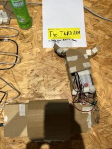
Posters with instructions that I wrote for the game:
![]()
![]()
Adapation:
A major adaptation I did to the project is to change the detection sensor. At the beginning of the project, I was using an ultrasonic sensor to detect. The problem with ultrasonic is the detection distance was too small for my project. Then after talking to LA about a method to increase distance, they suggest infrared. After switching to infrared, I had to redo my code and wire. This change was beneficial since it created a bigger area for users to place wood props in and compete with.
Another adaption is the suggestions from User Testing. During User Testing, many testers suggested a way to destroy the enemy wood “spaceships” since before there was no way to show how the user had actually detected the enemy “spaceships”. I added a rubber bullet gun so when the user detected the enemy “spaceships”, they can simply use the gun to shoot it to remove it from the game. This allow the user to be more immersive into the interaction.
2. FABRICATION AND PRODUCTION:
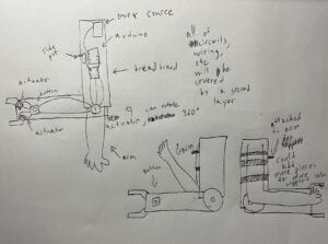
The first step is to create a rough sketch of the project. The picture below is a sketch of my beginning idea of what the project is like:
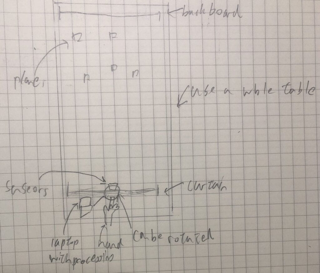
To make the game function: I created the project with four main components: The Control Box, The Rotation Radar, The Detection Screen and The Wood Props.
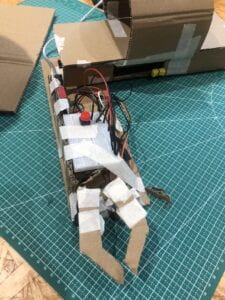
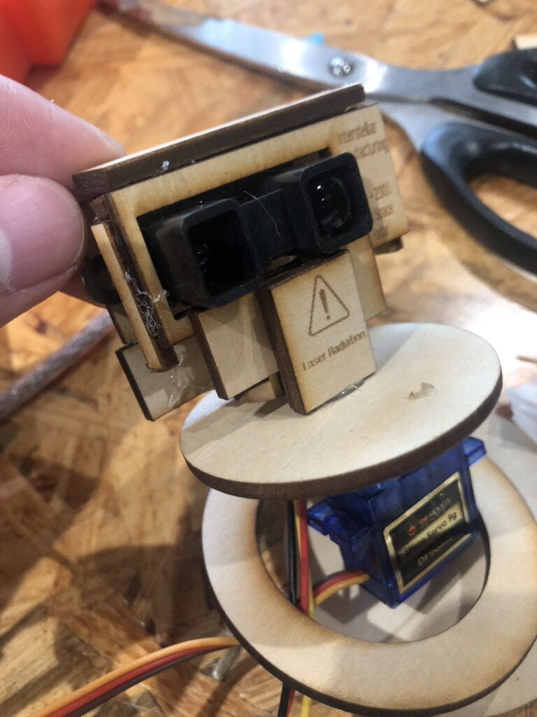
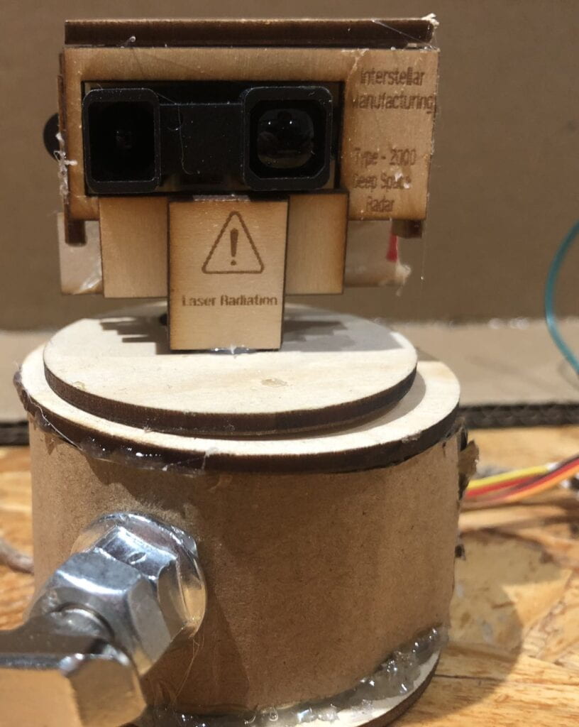
The Rotation Radar:
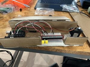
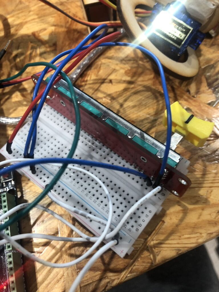
An infrared sensor is attached to the servo which will turn based on the input from the Control Box. Infrared sensor will give serial communication of the distance to the Detection screen. I designed it so that it will only turn 110 degrees to fit the detection range within a table. For the material that builds up the outer components, I use 1.5mm wood that was lazer cut by laser cutter. I chose this method because it is clean and easy to assemble. I then glued them together using a hot glue gun.
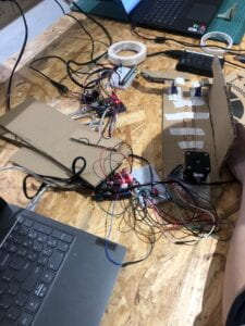
Changes I made to this component is that at first I used ultrasonic sensors to detect objects, however its detection range is too small for my project. I then switch to Infrared sensors. This is where I encounter a problem: the wire from the Infrared sensor was too thin to fit into the breadboard for Adurino. I had to solder each one of them to a jump cable. After this was done, I had to redo the coding in Arduino to fit the new sensors.
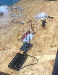
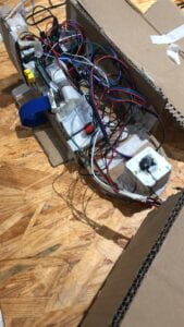
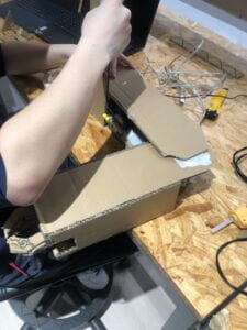
Building the radar box and the solder connection:
![]()
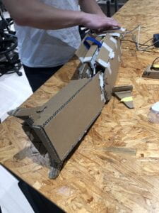
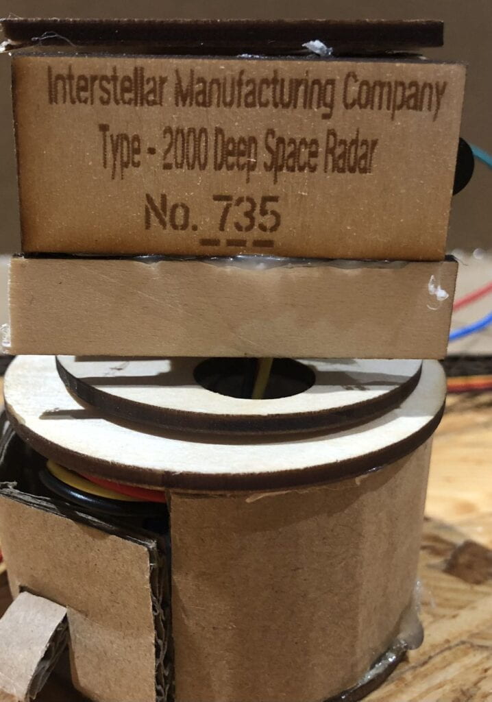
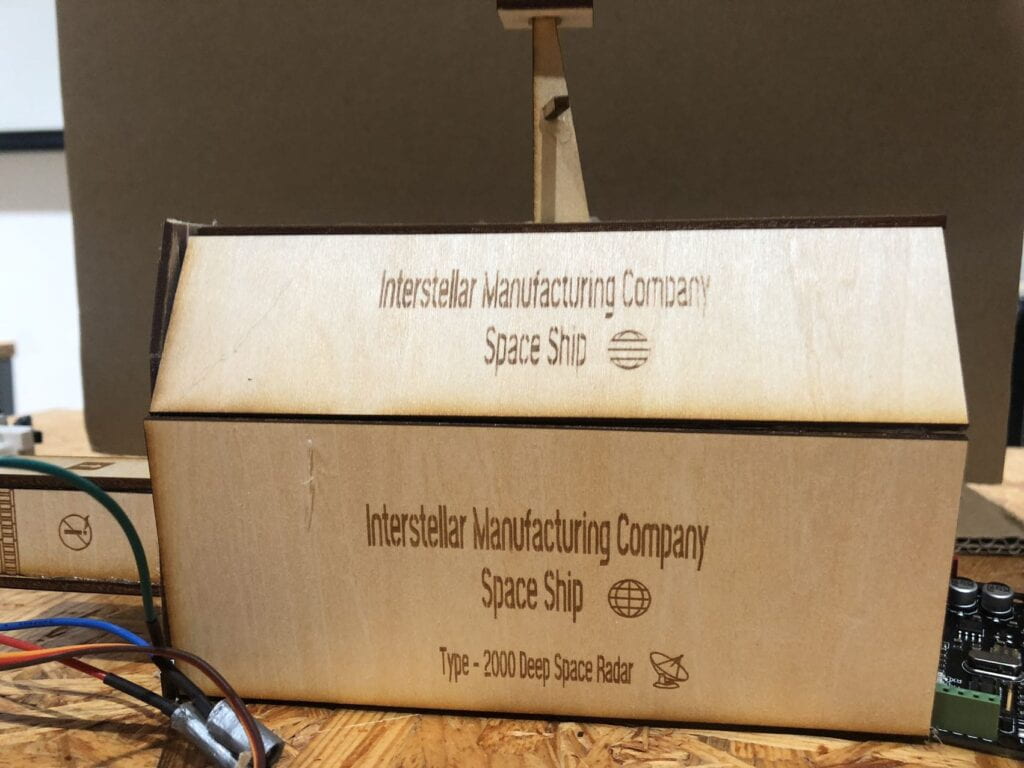
Finish Product:
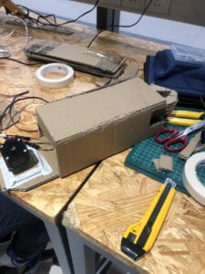
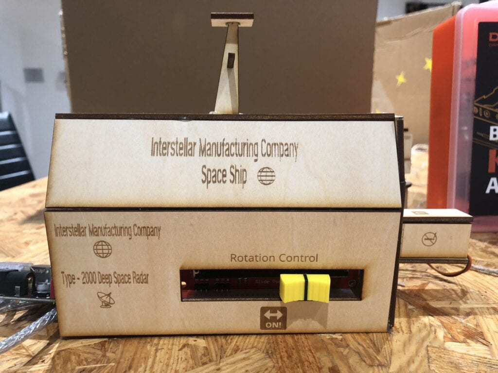
The Conrtol Box:
To make it simple for users to interact with, the “radar” is attached to a servo which is turned by a slider within the Control Box. Through sliding, the “radar” can change its angle of detection. The box is designed in simplicity so the user will know where to interact. The reason why I chose slider is because it is the most straightforward method for users to interact with the servo. Users when they see a slider will know immediately it is to slide and control the servo. By adding it to the box, users will be knowledgeable about how the servo turns after a few tries.
For this component, I choose 1.5mm wood as well. I did a design on Cuttle then performed a laser cutting to produce the parts that needed to be assembled. I also use laser cutting to etched on wood parts to make this component more realistic and attractive.
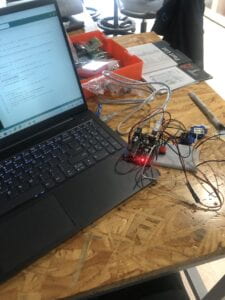
The finish wiring:
Finish Product:
The Detecton Screen:
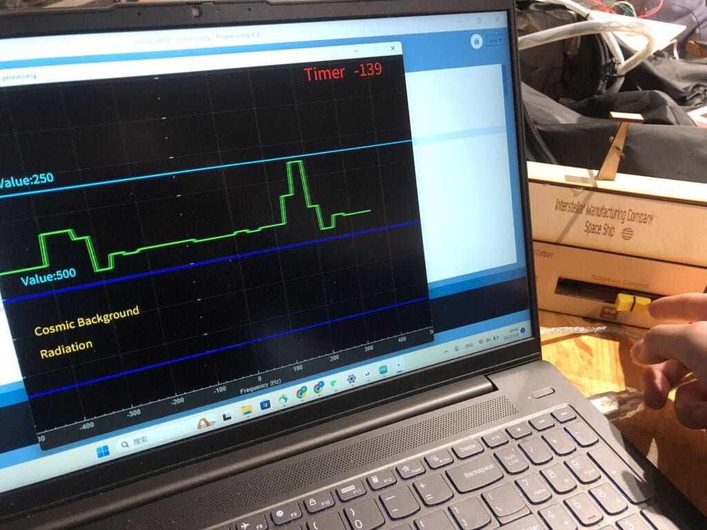
The serial communication form Audnrio is forward to Processing. The distance of the detection is displayed visually as a continuous line, when an object is detected there will be a spike. When there is nothing but the background, there will be a low value displayed. To make this component interesting, users can see when an object is detected or not. On the user interface, the continuous changing line will give the user the desire to discover the interaction of infrared sensors. Furthermore I also added a repeating sonar sound and a sonar range image background into Process, this makes the user further immersive themself into the game.
This part is where I spent the most time in designing and editing. I first tried to build a serial communication between Audnrio and Processing. This was relatively easy since I had to only follow the code in recition I did. The difficult part is how to display this input as a continuous line. I tried various methods yet they did not work. Professor Parren helped me with the coding and after editing for half an hour the input data is displayed as a continuous graph. I then added lines and numbers onto the screen through “text” and “line” to mark whether the changing line is in the range of background (Cosmic Background) or an object detection (Value: 0-500). Lastly I added a timer that will do a countdown for the user. This made the game more intense and fun.
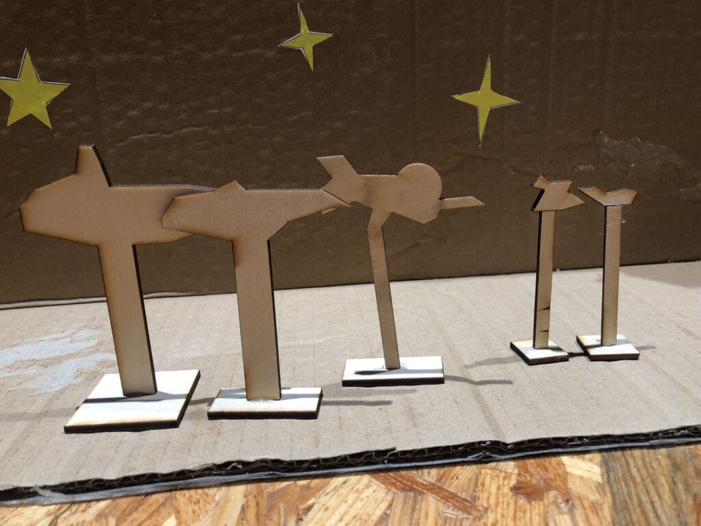
Wood Props:
I designed 5 wood props on Cuttle and did laser cutting to make them. 3 of them are enemy spaceships and 2 of them are small asteroids that are used to fake detection signals for the radar operator (As on the detection screen, the two asteroids will have a similar appearance as enemy spacecrafts). One of the two Users who act as the attacker will place them randomly before the game starts.
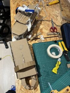
Laser cuting and gluing them togther
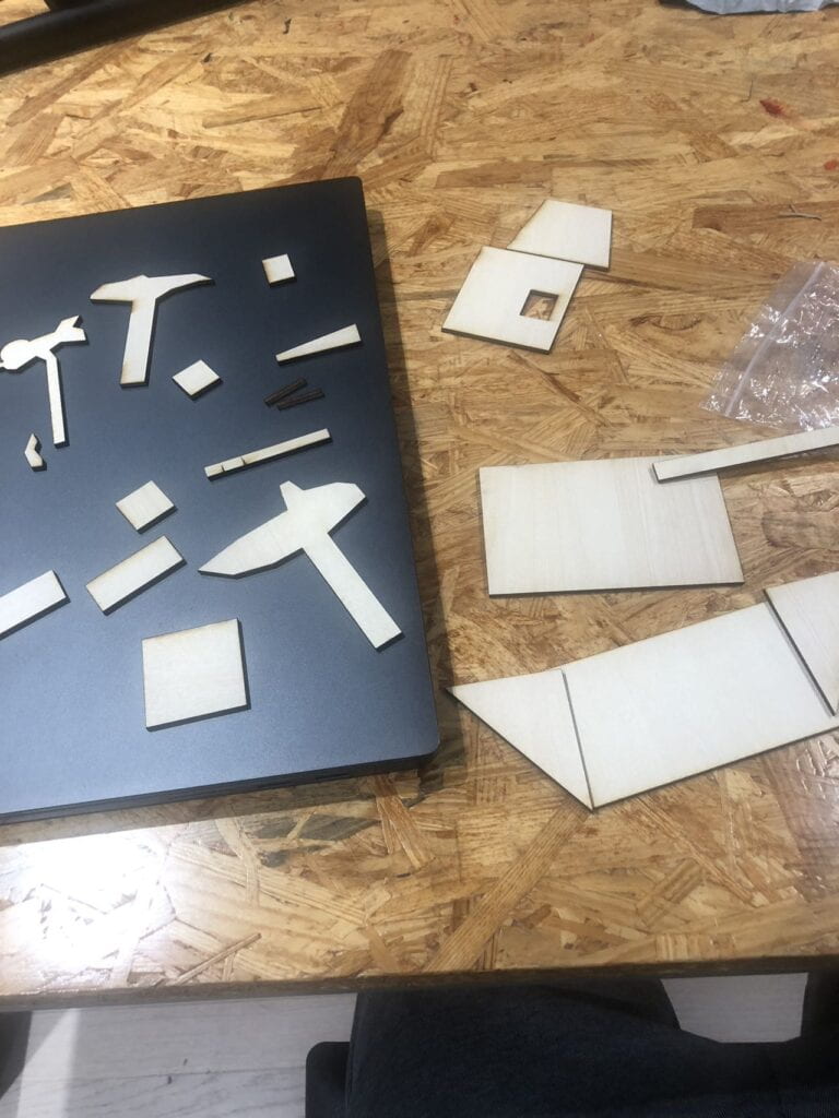
Finish Product:
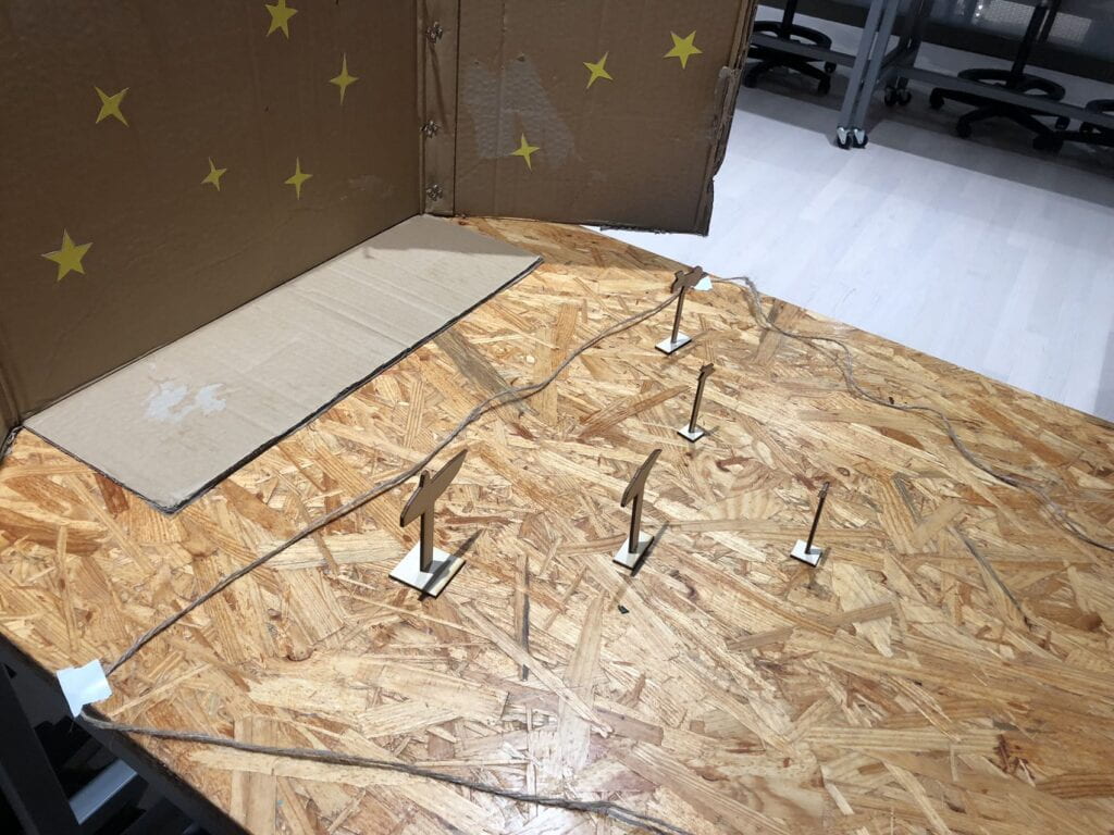
The Final Product:
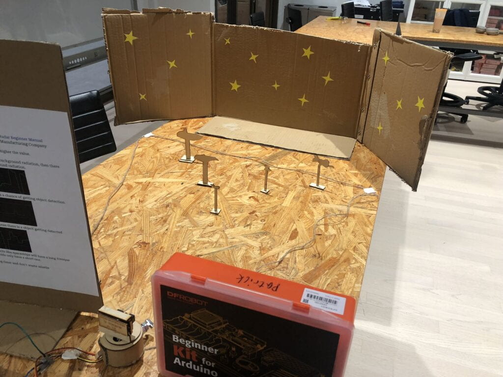
Radar detecting enemy spaceships with a cosmic background
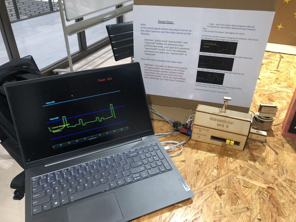
Virtual displaying the serial inputs and the Control Box
Video of playing the game:
Turning the radar with a slider
Detecting whether there is a spaceships or not (Cosmic Background range is nothing, spaceship detection: Value from 0-500.)
Shooting the wooden props with the rubber bullet gun when a player discover where it is
3. CONCLUSIONS:
The goal of this project is to create interactive experiences through Audrino and Processing. I hoped that through the game I created using Processing and ultrasonic, I could create an immersive experience for users to interact with. I believe that my project did meet that goal yet it requires the user to play the game a few times to understand how every components work before they can truly enjoy the interactive experiences. Based on my expectations, ultimately the audience will interact with my project through rotating the servo with a slider to read the distance of detection on Processing.
If I had more time to improve my project, I would like to make the diagram on detection screen from the 1D line into a 2D map of the table. This way the user will have a clear understanding of the location and what is displaying on the screen. This was a problem that I encountered in the final presentation where users don’t understand what is being displayed on Processing when they first try the game. I think if this is achieved, my game will be more immersive and easy to get hands on.
I think my project aligns with my definition of interaction quite well. Apart from Processing, the interaction is very simple and easy to understand. Users only have to slide a slider to control the servo. The game is very immersive and will make users stick to this project and immersive themselves into it. Lastly, by using infrared, it creates a new experience for users. This brand new experience will hook users to try this game themselves.
From this experience, the mistake I learned is that for users, there should be clear feedback or instruction. It is very hard for them to understand a complex interaction quickly. By making the game simpler, in fact it increases their likely chance of being immersive. A take away from my accomplishment is that people really like competitive games. By creating a game that requires two users to compete with each other, it can make the whole experience more interactive for both users.
In summary, my project delivers to users an interactive experience with the combination of Processing and Adurino. Users through interacting with my project can walk away with not only a joyful experience, but a deeper understanding of what interaction can be.
4. APPENDIX:
Adurnio Code:
Processing Code:
import processing.serial.*;
PFont font;
String time = "023";
int t;
int interval = 43;

import processing.sound.*;

Serial serialPort;


SoundFile sound;
int xPos = 1;
float inByte = 0;


int NUM_OF_VALUES_FROM_ARDUINO = 1;  /* CHANGE THIS ACCORDING TO YOUR PROJECT */
PImage photo;
/* This array stores values from Arduino */
int arduino_values[] = new int[NUM_OF_VALUES_FROM_ARDUINO];

float lineLength = 0;
float lineElements[] = new float[200];

void setup() {
  size(1162, 900);
  background(0);
  photo = loadImage("image.png");
  println("Loading mp3...");
  sound = new SoundFile(this,"Sonar1.mp3");
  sound.loop();


  printArray(Serial.list());
  // put the name of the serial port your Arduino is connected
  // to in the line below - this should be the same as you're
  // using in the "Port" menu in the Arduino IDE
  serialPort = new Serial(this, Serial.list()[0], 9600);

  serialPort.bufferUntil('\n');

  for(int i=0; i<lineElements.length; i++) {
    lineElements[i] = 0;
  }
}

void draw() {
getSerialData();

  image(photo, 0,0);
   stroke(255,0,0);
   strokeWeight(3);

   t = interval-int(millis()/1000);
    time = nf(t , 3);
    if(t == 0){
      println("GAME OVER");
    interval+=0;}

textSize(30);
 strokeWeight(3);
   fill(0, 255, 255);
text("Value:250", 50, 230);


  textSize(30);
 strokeWeight(3);
   fill(0, 255, 255);
text("Value:500", 50, 470);

   stroke(0,200,255);
 strokeWeight(3);
 line(0,250,1162,250);


  stroke(0,0,255);
   strokeWeight(3);
  line(0,750,1162,750);
     strokeWeight(3);
  line(0,500,1162,500);


textSize(30);
 strokeWeight(3);
 fill(255,200,0);
text("Cosmic Background", 50, 600);
text("Radiation", 50, 660);

textSize(50);
 strokeWeight(3);
 fill(255,0,0);
   text(time, 1000, 50);
     fill(0, 255, 0);

textSize(50);
 strokeWeight(3);
 fill(255,0,0);
 text("Timer", 850, 50);

  line(xPos, height, xPos, height - inByte);

  // at the edge of the screen, go back to the beginning:
  if (xPos >= width) {
    xPos = 0;
    background(0);
  } else {
    // increment the horizontal position:
    xPos++;
  }

  if(arduino_values[0] < 150) {
    lineLength = map(arduino_values[0], 0, 150, 0, height);  /// THIS MAPS DISTANCE IN CM TO SCREEN COORDINATES
    float lineElementsCopy[] = new float[lineElements.length];
    arrayCopy(lineElements, lineElementsCopy);
    printArray(lineElements);
    lineElementsCopy = append(lineElementsCopy, lineLength);
    printArray(lineElementsCopy);
    lineElements = subset(lineElementsCopy, 1);
  }
  stroke(0,255,0);
  strokeWeight(3);
  for(int i=0; i<lineElements.length-1; i++) {
    line((width/lineElements.length)*i,lineElements[i], (width/lineElements.length)*(i+1),lineElements[i+1]);
  }

}

void getSerialData() {
  while (serialPort.available() > 0) {
    String in = serialPort.readStringUntil( 10 );  // 10 = '\n'  Linefeed in ASCII
    if (in != null) {
      print("From Arduino: " + in);
      String[] serialInArray = split(trim(in), ",");
      if (serialInArray.length == NUM_OF_VALUES_FROM_ARDUINO) {
        for (int i=0; i<serialInArray.length; i++) {
          arduino_values[i] = int(serialInArray[i]);
        }
      }
    }
  }
}