The gripper – Pratirck Wang/Justin Lau – Instructor: Eric Parren
Welcome, this blog is to report me and my teamate Justin collaboration work for IMA Midterm project.
- CONTEXT AND SIGNIFICANCE
After we submitted our proposal, we decided to stay with Jason’s idea. He wanted to create a robotic arm that when attached to the left arm can be moved by itself. It can help the wearer to pick up or hold items. It can be helpful to seniors or people with disabilities to grab an item. The interaction is that through the button and slider, the arm can rotate 360 degrees and can grip on to the item. The interaction is that humans give input to the machine, and the machine gives feedback by moving its arm or grip. During past recitation, we know the most difficult part of the Arduino project is coding. Furthermore as we have just learned how to use servos, we decided to implement it in this project. Therefore we want to create a project that is simple and easy to use. There should be no confusing interaction or components.
2. CONCEPTION AND DESIGN
We knew that this project must be made durable as it is built for users wearing and testing. Furthermore in order to make the project functionable, we decided that it has to be lightweight. This eliminated any heavy material like metal or wood. Therefore we pick cardboard to be the main components of the build. The upper arm, forearm and grip will also be made of cardboard. Since we have gained experience working with servo in recitations and the group project, we picked it to serve as the part for movement of the arm and grip. This ont only saves time but also is more practical compared to other components.
Here is a rough sketch of our idea:
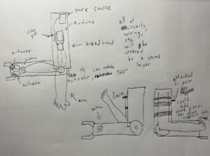
The machine is attached to the upper arm. The button and slider is placed perpendicular to the arm and after pressing it can be moved and grip by itself.
Material lists:
- Cardboard
- Duct tape
- Hot glue
- Two Arduinos
- Two Arduino cables
- Two breadboards
- Three servos (This later changed to two servos and one stepper motor)
- One button
- One slider
- Some M/M and F/M Wires
- FABRICATION AND PRODUCTION
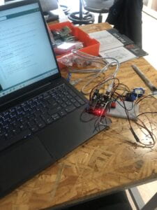
First: Our goal is to create a prototype for user testing.
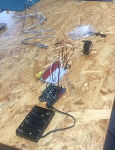
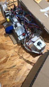
I started to cut the cut cardboard to form the shape while Jason connected the wire. Jason tried to use a 5 pack battery supply to power the servo (We originally designed that there is no need for the arduino cable). However it did not work and LA told us that the 5 pack battery can not power the servo. Therefore we changed the design back to using arduino cable. Jason progarmed the servo in the picture that controls the arm movements.
Afterward I tried to program the two servos that control the grip. I encountered a problem as the two servos had to be connected to one button. I tried to code it for two hours and it came out fruitless. I asked a professor to help me with coding (I don’t have any experience with coding, this is really difficult for me). After some trying the, the grip worked.
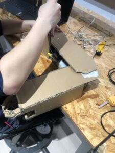
Then we started to tape everything together:
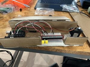
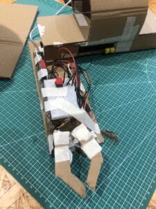
This is where we started to encounter the problem that will last through the entire project. The forearm, even being built of cardboard, is to heavy for the servo to lift. We planned so that if we push the slider the forearm can rotate 360 degree. But when we tried it can only move 20-30 degrees from the positions of forearms pointing to the ground. We tried to solve it by sticking wires through the servo. Although it is shaky it can now move almost 360 degrees. We were happy with the result and present it for user testing to get feedback.
Second: User testing and Feedback
We presented our project to many students and most are impressed by our design. They really liked how the arm can rotate 360 degrees. Some feedback is to create some props for the grip to pick up. This can make it more interesting and interactive. Another suggestion is to change the location of the slider and the button. The location on the protype is perpendicular to the arm. They suggest moving it parallel to the arm and also place them together. After some discussions with Jasons, we decided to listen to their suggestions and move it. This modifications later become successful as it is more friendly for user to interact with.
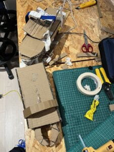
Third: Building the final products
For the final product, we want to build a brand new one since the prototype is crude and fragile. Jason thought that by replacing the servo with a stepper motor on the upper arm, it can hold the forearm completely. I agreed with him and we started working on that. A stepper motor is very different from a servo. I had to redo the wire and cricut to make it work.
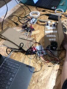
I encounter the issue of coding again since I have no experience with sliders being the input to control the stepper motor. I asked for help again and with clarification from the professor and the problem was solved.
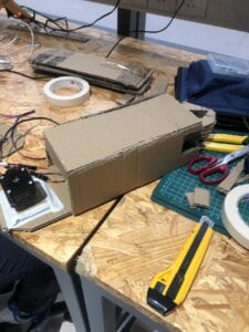
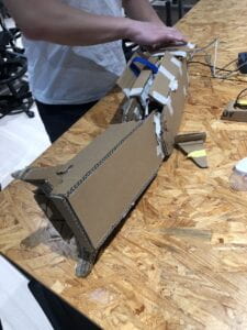
Jason and I taping the upper arm and forearm
Just as we thought all the problem was solved, the issues of the heaviness of the forearms come back again. Even with the stepper motor replacing servo, it still can not rotate. We tried to increase the motor rotate speed and it was still useless. In the end we just give up with the notion of the rotation of the forearm by a stepper motor. We added a handle to the forearm for the user to hold and rotate. This solves the issue of the stepper motor not being able to rotate. (It is a failure since our original design is that the forearm can rotate 360 degrees by itself, now it has to be held up by the user’s forearm.)
We also move the button and slider to the positions that was suggested in user testing
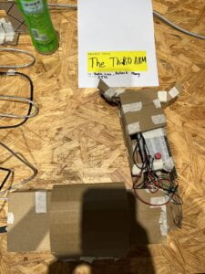
Finished product:
Video of trying the product out:
Code for controlling stepper motor with a slider:
//
#include <AccelStepper.h>
const int potPin = A0;
int DIR_PIN = 2;
int STEP_PIN = 3;
int EN_PIN = 4;
// Define a stepper and the pins it will use
// AccelStepper::DRIVER means a stepper driver (with step and direction pins)
AccelStepper stepper(AccelStepper::DRIVER, STEP_PIN, DIR_PIN);
int pos = 0; // variable to store the servo position
void setup() {
pinMode(potPin, INPUT);
pinMode(EN_PIN, OUTPUT);
digitalWrite(EN_PIN, LOW);
// The run() function will accelerate up to
// the speed set here
stepper.setMaxSpeed(2000);
stepper.setAcceleration(2000);
// Set the desired constant speed for use with
// runSpeed()
stepper.setSpeed(2000);
stepper.setCurrentPosition(0);
stepper.runToNewPosition(0);
Serial.begin(9600);
}
void loop() {
int sensorVal = analogRead(potPin);
int motorAngle = map(sensorVal, 0, 1023, 0, 100);
// Serial.println(motorAngle);
stepper.moveTo(motorAngle);
stepper.run();
delay(1);
}
Code for controlling two servos with one button:
#include <Servo.h>
Servo myservo;
Servo myservo1; // create servo object to control a servo
// twelve servo objects can be created on most boards
int pos = 0; // variable to store the servo position
// digital pin 2 has a pushbutton attached to it. Give it a name:
int pushButton = 2;
int prevButtonState = 1;
void setup() {
myservo.attach(8); // attaches the servo on pin 9 to the servo object
myservo.write(pos);
myservo1.attach(12); // attaches the servo on pin 9 to the servo object
myservo1.write(pos);
pinMode(pushButton, INPUT);
Serial.begin(9600);
}
void loop() {
int buttonState = digitalRead(pushButton);
if((buttonState == 0 && prevButtonState == 1) && pos == 0) {
pos = 90;
myservo.write(pos);
myservo1.write(pos);
} else if((buttonState == 0 && prevButtonState == 1) && pos == 90) {
pos = 0;
myservo.write(pos);
myservo1.write(180);
}
prevButtonState = buttonState;
delay(10);
- Conclusions:
The goal of our project is to demonstrate our idea of a machine that can aid humans in the work environment in life by acting like a third arm. Furthermore it can give people with arm disability the chance to have an “arm” like function to improve their life quality. I think even though our end product is unsatisfactory compared to our original idea, I think it still showcased to our audiences that our idea could pave the way for it to be invented. The project we created demonstrated clearly to the audience how it functioned and what it could do. Although its interaction is simple, it fits my definition of interaction. Users send a signal through a slider or button to the machine. The machine give feedback to the user through movement. The machine is simple for users to understand, its function is similar to things they have used before and it is easy to master. Ultimately, our audience interacts with it through buttons and sliders. The machine responds by moving it and gripping things they desire.
I think if we had more time to improve the project, we would have found a way to solve the issues of rotation of the forearm. We later learned that another team used two stepper motors to move its arm. If we have time to use two stepper motors, our project forearm might be functionable. I think the biggest setback I learned from this project is don’t be overconfident. After user testing, we thought that by replacing servo with stepper motor, we can increase the forearm size and weight. We are too confident that nothing will go wrong and did not test the ability of the stepper motor until it was finished which resulted in the project being unsatisfactory. The take away from our accomplishments for me is to not give up. When we encountered the issue of the forearm being unliftable, we almost wanted to rage quit as we thought that there was no way to even lift the forearm by an inch. Then I gave the idea that we can attach the machine forearm to the real forearm. During the presentations, with some explaining to the user its original intentions and the difficulties we encounter, this problem was solved. If we gived up and stopped thinking of the alternatives, we would have failed the project. This is a very valuable thing I learned!