The Shape of You
Patricia Troncoso Riveira, Professor Margaret Minsky
CONCEPTION AND DESIGN:
The concept of the final project is a sculpture/body that represents human interactions. My partner and I wanted to start this project by improving on our midterm project. We were told in our midterm project that it was not interactive enough, so we wanted to improve on that. Originally, our final was going to be a sculpture with different sensors that, when activated, reacted in a certain way. We were going to add a bend, touch, and distance sensor. For example, if the touch sensor is activated, then the program would show something, but if the distance sensor was activated, then the program would show something different. When the idea was presented to our instructor, she raised reasonable concerns about the ergonomics of our sculpture and the bend sensor. As we started the building process, the structure changed into a mannequin, and we were not sure how to build the sculpture. When we changed the final into a mannequin with the sensors, the concept slowly changed to more of a representation of human feelings, especially concerning affection. User testing really helped with giving a purpose to the project, as all the users assumed that it was about how humans deal with affection. After user testing, we decided to fully focus on that ‘affection’ and programmed the responses to resonate with that feeling. After making those changes, the concept became more concrete, and therefore the project was better understood by the users.
FABRICATION AND PRODUCTION:
Initially, our idea was to make a sculpture and use touch, distance, and bend sensors. Each sensor would provoke a different response. There was no concrete design for the sculpture. Because each sensor was supposed to evoke different reactions, our professor was worried about how the bend sensor would work, because when you bend something it normally stays in that place, so the question was, what is the user supposed to do after bending the sculpture, bend it back? Another concern also had to do with the fact that there are not many bendable materials that would make a stable structure, and a lot of bendable materials tend to break after bending several times.
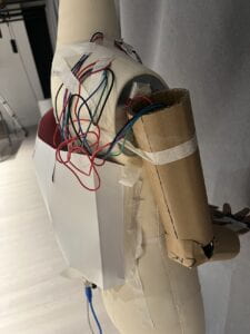
When the fabrication process started, we ended up deciding on changing the sculpture to a mannequin, as it would save us a lot of time trying to figure out the materials and form of the sculpture. We also decided to forgo using bend sensors, as there were too many concerns about them, instead, we were to use a distance sensor and more touch sensors in different parts of the mannequin, simulating human touch.
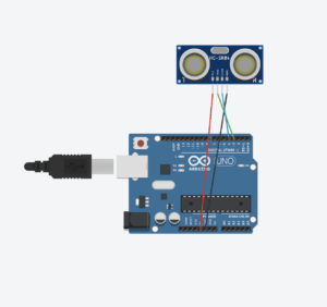
For the distance sensor, we decided to make a program that would simulate a heartbeat, the closer you are to the mannequin, the circles in the computer screen would compress and release. This acts as the feeling of when someone hugs you. The distance sensors did not give us any issues. We presented the project in the prototype presentation with the distance sensors and they worked well, so we only had to do a few tweaks in the code.
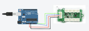
The touch sensors, we were not sure how they worked, and the equipment room did not have many, and with the time constraints, we settled on using one touch sensor. We had to look through many tutorials to understand how the sensors worked. The touch sensor was a Grove IC2 touch sensor, that had four touch feelers. When we saw the feelers, we decided to give the mannequin arms and install the sensors in a hand to simulate touching hands and the feelings behind it. To utilize the sensors, we were inspired by a code from the website electropeak.com, where the code detects which of the touch feelers was being activated. After we modified the code and connected it to processing, we designed a code, that when activated would show hearts, implying nervous excitement when two people join hands. The problem was, that the sensors were not very sensitive, so sometimes the touch feelers did not get activated when being touched.
Another problem that we had was when using 1 Arduino and connecting both the distance and touch sensors, none of the sensors would work, after many attempts, and eventually asking a professor, we figured out that each of the sensors needed 5V individually, so one Arduino connected to one computer, would not be enough power for both sensors. There were two solutions for this, we used a 5V power supply and merged the codes for both touch and distance sensors, or we used two Arduino and therefore two computers. We ended up using two monitors as the merging of the codes was giving many problems and there were time constraints.
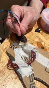
Another great issue we had during the fabrication process was that whilst we were doing the cabling and assembly of the sensors and the mannequin, there was a short circuit we were not aware of. While user testing, the Arduino would suddenly overheat, so the computer would not detect it and therefore not run the code. To figure out what the problem was, we had to disassemble the mannequin and go cable by cable to see if there was any contact or short circuit. We ended up discovering that it was, in fact, a short circuit in the touch sensor’s SLC, SDA, VCC, and GND area. In order to prevent this from happening again, we created dividers with plywood and then glued them so that they wouldn’t fall. After this, the sensors did not work, and we realized that it had been because we added too much hot glue. After getting rid of part of the glue the sensors finally worked.
CONCLUSIONS:
The goal for the final project was to create a sculpture that would create visuals depending on what sensors were activating, simulating human interactions, especially those involving romantic feelings. In the end, we were able to achieve our main goal. The audiences’ reactions during user testing exceed our expectations in comparison to our midterm project. My definition of interaction is that both the object and user have to reciprocate interaction, and our project did, as the user need to interact with the project so that the sensors could activate, and the sensors needed to be activated by the user to produce the visual. If we had more time, we could have successfully merged the codes and maybe use a large monitor to better display the visuals. We could have also added more sensors, such as vibration and bend sensors, to diversify the user sculpture interactions and explore a wider range of feelings/emotions. Another thing we could have done is do representations with more than processing visuals, for example, sounds and neopixel, as this would have elevated our project.
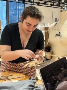
We have learned a lot throughout this project, especially patience and thinking outside the box. We have had several problems with the project and had to be very creative with our solutions. After research and guidance from the professors, we would test many methods to solve problems that we normally wouldn’t think of. When the short circuit happened with the sensors, we initially thought it was a programming problem and that our Arduinos were getting fried due to the code, but after asking for help, the possibility of it being a simple short circuit or contact between two cables was opened. We ended up having to manually wrap all copper ends and make sure no cables were touching. This was a very arduous task that took time, but it made us learn that not all problems derive from the programming aspect, but that a simple contact between two cables can be the detonating factor. This final project was very hard and patience-testing, but I am very thankful as I have learned new skills that will help me greatly in the future.
APPENDIX

User testing of final project.
Touch Sensors:
Arduino:
#include "SerialRecord.h"

SerialRecord writer(1);

#include <Wire.h> // include I2C library

#include <i2c_touch_sensor.h>

#include <MPR121.h>

// include our Grove I2C touch sensor library

// initialize the Grove I2C touch sensor

i2ctouchsensor touchsensor; // keep track of 4 pads' states

//boolean padTouched[4];

long previousMillis = 0;

long interval = 100;

void setup() {

Serial.begin(9600); // for debugging

Serial.print("begin to init");

Wire.begin(); // needed by the GroveMultiTouch lib

touchsensor.initialize(); // initialize the feelers // initialize the containers

}

void loop() {

unsignedchar MPR_Query = 0;

unsignedlong currentMillis = millis();

if(currentMillis - previousMillis > interval){

previousMillis = currentMillis;

touchsensor.getTouchState();

}

for(int i = 0; i < 12; i++){

if(touchsensor.touched){

writer[0] = 1;

}

else{

writer[0] = 0;

}

delay(200);

writer.send();

}

}
Processing:
import processing.serial.*;
import osteele.processing.SerialRecord.*;

Serial serialPort;
SerialRecord serialRecord;
int touch1, touch2;

int prevVal = 0;

void setup() {
  fullScreen();
  background(0);
  smooth();

  // Find and connect to the Arduino board
  String serialPortName = SerialUtils.findArduinoPort();
  serialPort = new Serial(this, serialPortName, 9600);
  serialRecord = new SerialRecord(this, serialPort, 1);
}

void draw() {
  // Read data from Arduino
  serialRecord.read();

  int val0 = serialRecord.values[0];

  if (val0 == 1) {
      float a = random (width);
      float b = random (height);
      float r = random (100, 255);
      smooth();
      noStroke();
      fill(r, 0, 0);
      beginShape();
      vertex(a+50, b+15);
      bezierVertex(a+50, b-5, a+90, b+5, a+50, b+40);
      vertex(a+50, b+15);
      bezierVertex(a+50, b-5, a+10, b+5, a+50, b+40);
      endShape();
  }
  else {
    background(0);
  }
}
Distance Sensors:
Arduino:
#include "SerialRecord.h"

#include <FastLED.h>

#include <NewPing.h>

#define TRIG_PIN 3

#define ECHO_PIN 4

#define MAX_DISTANCE 200

NewPing sonar1(TRIG_PIN, ECHO_PIN, MAX_DISTANCE);

SerialRecord writer(1);

int val0;

void setup() {

  Serial.begin(9600);

}

void loop() {

  sensor();

  val0 = sonar1.ping_cm();

  writer[0] = val0;

  writer.send();

  delay(10);

}

void sensor(){

  delay(50);               // Wait 50ms between pings (about 20 pings/sec). 29ms should be the shortest delay between pings.

  Serial.print("Ping1: ");

  Serial.print(sonar1.ping_cm()); // Send ping, get distance in cm and print result (0 = outside set distance range)

  Serial.println("cm");

}
Processing:
//libraries
import processing.serial.*;
import processing.sound.*;
import osteele.processing.SerialRecord.*;

//Arduino stuff
Serial serialPort;
SerialRecord serialRecord;
SoundFile sound1;

//yuuh
float firstTerm = 1;
float secondTerm = 1;

//shit ton of ints
int x = 0;
int b = 0;

void setup() {
  fullScreen();
  background(0);

  //Arduino
  String serialPortName = SerialUtils.findArduinoPort();
  serialPort = new Serial(this, serialPortName, 9600);
  serialRecord = new SerialRecord(this, serialPort, 1);
}

void draw() {
  serialRecord.read();
  int value0 = serialRecord.values[0];

  if (value0 <= 10) {
    drawBalls();
  }

}

void drawBalls() {
  for (int i = 1; i < width; i = i + 20) {
    for (int j = 1; j < height; j = j + 20) {
      fill(0);
      noStroke();
      ellipse(i, j, firstTerm * 1.5, firstTerm * 1.5);
      fill(random(260, 280), 90, 50);
      stroke(0);
      strokeWeight(random(1, 5));
      ellipse(i, j, firstTerm, firstTerm);
    }
  }

  float nextTerm = firstTerm * 1.5;
  firstTerm = secondTerm;
  secondTerm= nextTerm;
  if (firstTerm >= 20 || secondTerm >= 20) {
    firstTerm = 1;
    secondTerm = 1;
  }
}


void drawBack() {
  background(0);
}
POTENTIAL IDEAS:
We wanted to add more elements but due to time constraints and mechanical problems we were not able to, we had made the designs but were not able to execute them:
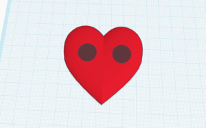
3D PRINTED HEART: We wanted to 3D print a heart to put it where the distance sensors are. We would put to holes in it, the sizes of the sensors so that it would still work.
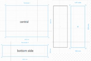
LASER CUT BOX: Our initial idea was to laser-cut a box to hide the cabling. It was supposed to fit like a backpack. The laser cutter was not working at the time and therefore did not execute the plan. The box would have had the top side of it open so that we could move cables if needed.
This is the website where we got the inspiration for our touch sensor code:
https://electropeak.com/learn/interfacing-grove-12-key-multi-touch-sensor-with-arduino/