
Lighting Connection- Kelly Liu – Professor Inmi Lee


Conception and Design:
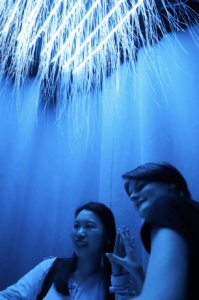
Our projects concept revolves around the idea of being able to see the importance of connection through the form of human touch. Our intention was to help our audience come to the consensus that through human connection we are able to see the light. In order to achieve this goal our inspiration came from various similar art projects (Cho). These projects helped us to develop our own take on similar projects, which was to be able to light up a light installation when people engage in human touch. We saw an opportunity in using the LED strips that we had explored in class and attaching fibre optics to the LED strips to create an aesthetic environment with fibre optics hanging down from the ceiling. We were able to visualise the environment that the fibre optics would create through attending the fellows exhibition, in which fibre optics were used in the project as well as our individual research on how to build installations using fibre optics and light. As for the technicality of building a circuit that allows human connection to light up an LED strip, we learned from our Professor that we were able to build a human circuit, as the human bodies are conductive. We knew we wanted to learn more about building a human circuit through different sources. Relating to the circuit we realised we also needed to give the audience members to hold onto that was able to conduct and ultimately light up our installation. At first, we decided to use two wooden sticks, wrap them in copper tape, and solder them to wires that connect back to the circuit, however after our user testing, the most prominent feedback was to create a more obvious or guiding conductors instead of the wooden sticks we created, so we laser cut two hands and wrapped them in copper tape and stuck them to a pedestal in the middle of our installation. We also learned that in user testing, two entrances would make a great impact as it helped our project to direct two audience members to come in from two different sides of the curtains and meet in the middle to connect. This was able to create an environment that was more appropriate to that of an installation for exhibits.

Before the user testing we also only managed to create one constant colour of the LED strips which we also were advised to improve and create different changing colours and patterns on the LED strips. After we tried to learn how to include colour palettes into our code so that we could create different colours and patterns that could represent the biological reaction of human touch in one’s body. This was also able to help advance our project into a more aesthetically pleasing installation. From our user testing session we also learned that we needed to create an even darker environment in order for the fibre optics to light up even more. Overall, we made decisions on our project based on the assumptions and perspectives from the creators instead of from the perspective of the audience. However, after the user testing session, the feedback helped us a great amount to further improve our project given the input from the audience’s perspective. This allowed me to learn the importance of trying to put myself into the shoes of the audience members and to help create a clear yet poetic guide for the audience to ultimately reach and understand the intention behind a project.
Fabrication and Production:
Our production process started with the decision to build a human circuit based on an online video tutorial (I want to hold your hand). This tutorial showed us how to build the circuit so that when two or more people people touch while holding a conductive wire or pole connected to the circuit it would complete the circuit and start playing an audio in processing. The video online made use of an Arduino Nano, so at first we tried to build a replica circuit on an Arduino nano we borrowed from the ER, but soon after, we discovered that the Arduino Uno that we had would also work out, so we decided to build it on the Arduino Uno since we were more familiar with it. We struggled to find the right capacitor for the circuit, however in the end a Fellow helped us find the highest capacitor we had. Instead of letting the circuit play a music file, we changed the circuit to light up an LED light at first. The code was also learned from the same video tutorial, however we struggled on finding the right threshold as the light kept switching on and off showing the instability of the values being sent to Arduino. Because of the instability we could not find a way to switch the LED on and off in a stable manner so we considered using a touch sensor. However, we ultimately ruled out this idea as we agreed that it did not contribute to our intention of people connecting through human touch as the audience members would have to wear something or have something on their skin which created a barrier between the human touch. We knew that this would take away from our main goal of our project so we continued to explore different thresholds, until we found one that was less problematic than others.
After we knew the circuit was working and sending values to Arduino, we tried to connect them to 10 LED Strips instead of one LED. After, we had to work on the code for processing. Figuring out how we could get Arduino to send values to processing and allowing processing to play a sound file when the values were sent took a long time. We attempted many times and different codes to make the sound file play in processing but none of them seemed to work, so we asked the Fellows for help. We also worked on the colour palettes in processing to create a more aesthetically pleasing environment after hearing feedback from our user testing.
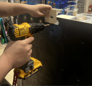
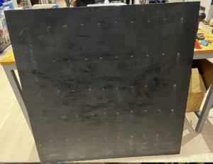
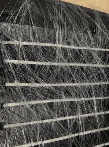
Then we had to move on to the fabrication of our project in which we had to start by consulting with our Fabrication lab specialist, Dalin. Originally, we thought we needed to create a wooden grid so that we could attach the LED strips to it, however we decided that a larger sized wooden plank would be easier as we could just stick on the LED strips. We measured the length of 10 LED strips to be around 1.2 meters so Dalin helped us to cut the excess wood off our wooden plank. We also painted the board in black paint since we knew we wanted our project to be in a dark environment. Then we realised that we could not stick the LED strips directly to the wooden board as we needed to return them, so we informed on how to make small holes with drills so that we could zip tie the LED Strips to the board. This was very time consuming as we had to make two holes for each Zip tie, so we made 100 small holes in total. Then we had to make 10 big holes at the edge so that the wires from each LED strip could go through it. We then secured each LED strip with zip ties and made sure they were tight and straight.

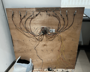
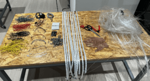
After securing the LED Strips to the board, we started elongating all the wires and soldering parts that need to connect to each other, for instance the wooden sticks at first and the hands later. Once we soldered and elongated all the needed wires, we started to connect them back to the Arduino and Breadboard. We also made use of an external power input as our computers were not enough to light up 10 LED strips. Then we had to figure a way to stick the fibre optics to each LED. We then had the idea of first attaching double sided tape onto the LED strip, then using hot glue to stick each fibre optic on to the LED strip. We cut the fibre optics into different lengths to achieve a flowy aesthetic when the lights switched on. Sticking on the LED strips was a very tedious task as we needed to make sure that the tip of each Fibre optic was directly on top of the light so that the light could shine through the optic to the end. We took extra precautions and stuck 3 fibre optics at a time with hot glue on to each LED on the strip. This meant that we stuck 1800 individual fibre optics on to each LED, as each strip had 60 LEDs and we had 10 strips.
The last step was to figure out how to hang our project up on to the ceiling, in which we made another consultation with Dalin, where he taught us how to make the hanging wires that would be clipped onto the ceiling grids. The wires were made by first measuring the height of where we wanted it to be hung at which was 2 meters from the ground, then we created a loop with a bolt at then end of it so that we could adjust the height of our project by taking the bolt out loose and taking in more wire, which would make the project go higher. We also were able to make use of the curtains from IMA, which really helped us put the project all together as the dark environment really helped the fibre optics to shine the light through from the LEDs. Overall we were given many options and challenges to overcome, that we were able to resolve with the help of the Professors, Fellows, and Learning assistants. We made many decisions based on our main goal and idea of how we wanted the project to look.
Conclusions:
The goals of our project are to entertain our audience through the concept of human touch and the benefits that human connection can bring to us. I believe that we achieved the entertainment part because of the aesthetic environment that we were able to create, however I do think that we could improve on making the concept a bit more clear to our audience. Although we tried to improve the guidance of our project intentions to the audience through changing poles to hands on a pedestal and through the title of the project, I believe that when we presented our project, some new audience members still needed clarification on the intention behind the project. With that said, when we explained the intention to our audience members it was very easy and clear for them to understand the meaning behind the installation. Most audience members were impressed by the aesthetic environment that we created and had good reactions to when the lights switched on through human touch. It was al relatively easy for the participants to realise that they needed to touch each other with their hands after we made the improvements to cut out two hand prints. However, one audience member also questioned that if they did no have their other hand on the hand prints we printed out and still made a connection through human touch, the lights would not switch on, which definitely go us thinking on how we could eliminate the hypocrisy of our intention and the technical design of our project. Although we are not sure yet in how we could further advance that part of the project, I feel that both my partner and I have grown a lot through the building process of our project and that we have developed our skills further, especially comparing to our Mid-term project.
Disassembly:
#define NUM_OF_VALUES_FROM_PROCESSING 1 /* CHANGE THIS ACCORDING TO YOUR PROJECT */

/* This array stores values from Processing */
int processing_values[NUM_OF_VALUES_FROM_PROCESSING];
int statepin = 13;

// Constants
const byte sensorPin = A0;
const int threshold = 600; //MAYBE PLAY AROUND WITH THIS TOMORROW, SEEMS TOO SENSITIVE
//const byte ledPin = 3; // Define the pin for the LED
int oldReading = 0;
// Enum for device state
enum DeviceState {INITIALISING, CIRCUIT_OPEN, CIRCUIT_CLOSED};
DeviceState deviceState = INITIALISING;

//Neopixel + music
#include

#define NUM_LEDS 60  // How many LEDs in your strip?
#define DATA_PIN 1
#define DATA_PIN 2
#define DATA_PIN 3   // Which pin is connected to the strip's DIN?
#define DATA_PIN 4
#define DATA_PIN 5 // There are a few too many, check which ones are actually connected and their position
#define DATA_PIN 6
#define DATA_PIN 7
#define DATA_PIN 8
#define DATA_PIN 9
#define DATA_PIN 10
#define DATA_PIN 11
#define DATA_PIN 12

CRGB leds[NUM_LEDS];
int next_led = 0;    // 0..NUM_LEDS-1
byte next_col = 0;   // 0..2
byte next_rgb[3];    // temporary storage for next color
int state;
//uint8_t paletteIndex = 0;
uint8_t colorIndex [NUM_LEDS];

DEFINE_GRADIENT_PALETTE(orangepink_gp) {
  100,   153, 204, 255,
         90, 225, 0, 255,
         200, 25, 25, 0,
         255, 255, 100, 0
};

DEFINE_GRADIENT_PALETTE(greenblue_gp) {
  0, 0, 20, 160,
  46, 0, 21, 255,
  179, 12, 150, 0,
  255, 0, 25, 245
};

// Gradient palette "healingangel_gp", originally from
// http://soliton.vm.bytemark.co.uk/pub/cpt-city/rc/tn/healingangel.png.index.html
// converted for FastLED with gammas (2.6, 2.2, 2.5)
// Size: 28 bytes of program space.

DEFINE_GRADIENT_PALETTE( healingangel_gp ) {
  0,  94, 156, 174,
  45,  66, 105, 166,
  84, 117, 117, 192,
  127, 173, 124, 156,
  170, 208, 108, 106,
  211, 197, 119, 73,
  255, 210, 221, 123
};

//CRGBPalette16 myPal = heatmap_gp;
//leds[i] = ColorFromPalette (myPal, 160);
CRGBPalette16 greenblue = greenblue_gp;
CRGBPalette16  healingangel = healingangel_gp;
CRGBPalette16 orangepink = orangepink_gp;

void setup() {
  Serial.begin(9600); // Start Serial communication
  //pinMode(ledPin, OUTPUT); // Set the LED pin as output
  FastLED.addLeds<NEOPIXEL, 1>(leds, NUM_LEDS);
  FastLED.addLeds<NEOPIXEL, 2>(leds, NUM_LEDS);
  FastLED.addLeds<NEOPIXEL, 3>(leds, NUM_LEDS);
  FastLED.addLeds<NEOPIXEL, 4>(leds, NUM_LEDS);
  FastLED.addLeds<NEOPIXEL, 5>(leds, NUM_LEDS);
  FastLED.addLeds<NEOPIXEL, 6>(leds, NUM_LEDS);
  FastLED.addLeds<NEOPIXEL, 7>(leds, NUM_LEDS);
  FastLED.addLeds<NEOPIXEL, 8>(leds, NUM_LEDS);
  FastLED.addLeds<NEOPIXEL, 9>(leds, NUM_LEDS);
  FastLED.addLeds<NEOPIXEL, 10>(leds, NUM_LEDS);
  FastLED.addLeds<NEOPIXEL, 11>(leds, NUM_LEDS);
  FastLED.addLeds<NEOPIXEL, 12>(leds, NUM_LEDS);
  FastLED.setBrightness(100);
  for (int i=0; i<NUM_LEDS;i++){
  colorIndex[i]= random8();
  }
}

void loop() {
  getSerialData();
  int reading = analogRead(sensorPin);
  //Serial.println(reading);

  switch (deviceState) { // Correct switch statement syntax
    case INITIALISING: // Correct case statement syntax
      // Perform any initialization tasks if needed
      deviceState = CIRCUIT_OPEN; // Move to the next state
      break;

    case CIRCUIT_OPEN:
      // If reading is less than threshold value, human circuit has been made
      if (reading < threshold) {
        state = 1;
        // Turn on the LED
        //digitalWrite(ledPin, HIGH);
        for (int i = 0; i < 60; i = i + 1) {
          //leds[i] = CRGB(5, 10, 205);
          //leds[i] = ColorFromPalette (myPal, 160);
          leds[i] = ColorFromPalette (greenblue, colorIndex [i]);
          //fill_palette (leds,NUM_LEDS,paletteIndex, 225/ NUM_LEDS,myPal,70,LINEARBLEND);
          //EVERY_N_MILLISECONDS (30){
          /*EVERY_N_MILLISECONDS (15){
            for(int i= 0;i<NUM_LEDS; i++){
              colorIndex [i]++;
            }
            //paletteIndex ++;*/
            EVERY_N_MILLISECONDS (7000){
              for(int i=0; i<NUM_LEDS; i++){
                leds[i]=  ColorFromPalette (greenblue, colorIndex [i]);
              }

          }

             EVERY_N_MILLISECONDS (7000){
            for(int i= 0;i<NUM_LEDS; i++){
             leds[i] = ColorFromPalette (healingangel, colorIndex [i]);
            }
            //paletteIndex ++;
          }
          EVERY_N_MILLISECONDS (4000){
            for(int i= 0; i<NUM_LEDS; i++){ leds[i] = ColorFromPalette (orangepink, colorIndex [i]); } } FastLED.show(); } // Send signal to Processing Serial.println("1"); // Signal Processing that LED is on // Optionally, perform any other actions you want // For example, you might want to print a message via Serial //Serial.println("Circuit Closed"); delay(100); } else { deviceState = CIRCUIT_CLOSED; // Move to the next state } break; case CIRCUIT_CLOSED: // If reading is more than threshold value, human circuit has not been made if (reading > threshold) {
        state = 0;
        for (int i = 0; i < NUM_LEDS; i = i + 1) { leds[i] = CRGB(0, 0, 0); FastLED.show(); } // Turn off the LED // digitalWrite(ledPin, LOW); // Optionally, perform any other actions you want // For example, you might want to print a message via Serial //Serial.println("Circuit Open"); delay(100); } else { deviceState = CIRCUIT_OPEN; // Move to the next state } break; } Serial.println(state); //Serial.println(digitalRead(13)); oldReading = reading; } void getSerialData() { static int tempValue = 0; // the "static" makes the local variable retain its value between calls of this function static int tempSign = 1; static int valueIndex = 0; while (Serial.available()) { char c = Serial.read(); if (c >= '0' && c <= '9') {
      // received a digit:
      // multiply the current value by 10, and add the character (converted to a number) as the last digit
      tempValue = tempValue * 10 + (c - '0');
    } else if (c == '-') {
      // received a minus sign:
      // make a note to multiply the final value by -1
      tempSign = -1;
    } else if (c == ',' || c == '\n') {
      // received a comma, or the newline character at the end of the line:
      // update the processing_values array with the temporary value
      if (valueIndex < NUM_OF_VALUES_FROM_PROCESSING) {  // should always be the case, but double-check
        processing_values[valueIndex] = tempValue * tempSign;
      }
      // get ready for the new data by resetting the temporary value and sign
      tempValue = 0;
      tempSign = 1;
      if (c == ',') {
        // move to dealing with the next entry in the processing_values array
        valueIndex = valueIndex + 1;
      } else {
        // except when we reach the end of the line
        // go back to the first entry in this case
        valueIndex = 0;
      }
    }
  }
}
Processing Code:
import processing.serial.*;
import processing.sound.*;

Serial serialPort;
SoundFile music;
boolean isPlaying = false;

int NUM_OF_VALUES_FROM_ARDUINO = 1;
int arduino_values[] = new int[NUM_OF_VALUES_FROM_ARDUINO];

void setup() {
  size(500, 500);

  // Load the sound file
  music = new SoundFile(this, "harp.mp3");

  printArray(Serial.list());
  // Put the name of the serial port your Arduino is connected
  // to in the line below - this should be the same as you're
  // using in the "Port" menu in the Arduino IDE
  serialPort = new Serial(this, "/dev/cu.usbmodem101", 9600);
}

void draw() {
  background(0);

  // Receive the values from Arduino
  getSerialData();

  // Play or stop the sound file based on the value received from Arduino
  if (arduino_values[0] == 0) {
    if (isPlaying) {
      music.stop();
      isPlaying = false;
    }
  } else if (arduino_values[0] == 1 && !isPlaying) {
    music.play();
    isPlaying = true;
  }
}

void getSerialData() {
  while (serialPort.available() > 0) {
    String in = serialPort.readStringUntil('\n');
    if (in != null) {
      in = trim(in); // Remove whitespace
      arduino_values[0] = int(in); // Convert string to integer
      println("Received from Arduino: " + arduino_values[0]);
    }
  }
}
Works Cited:
Cho, Joy, and jiyou Park. “Sea the Light_ Interactive Installation Art.” Behance, 2019, www.behance.net/gallery/93356731/SEA-THE-LIGHT_-interactive-installation-art.
“‘drop’: An Interactive Art Installation with Water Drop Projection Mapping.” YouTube, YouTube, 15 Jan. 2021, www.youtube.com/watch?v=BRLx4lMetu4.
“‘I Want to Hold Your Hand’ – Arduino Human Circuit.” YouTube, YouTube, 8 Feb. 2019, www.youtube.com/watch?v=m5PfKb8p1YI.