REVIVING — Xiao Zhou — Rudi
CONTEXT AND SIGNIFICANCE
“The Mogao Grottoes of Dunhuang have always attracted many tourists to come to see the scenery, but the carbon dioxide produced by human breathing will make the salt in the frescoes rapidly deliviate, thus accelerating the cracking and warping of the color layer of the frescoes, and finally powder and flake or become blurred.
In addition, the desert itself is dry and hot climate, wind erosion and dust accelerated the deterioration of the cave paintings. This is why only 12 caves are now open to the public.
Chinese and foreign experts estimate that the entire Dunhuang treasure will be buried in the sand in the next 50 to 100 years.”
It is sad but true that we have to face the fact that such a treasure will disappear irreversibly. Instead of standing there feeling regretful about grottoes, we need to find a new way to make them exist in the world forever. And we can just visit wonderful paintings without doing harm to them in an easier and more convenient way. So, this is the reason why I made this topic for my midterm project— REVIVING, as I want to make grottoes revive again. Also, in order to make the project more interactive, I decided to make characters in the wall paintings alive so that visitors(users) can have a more interesting and impressive experience. In the end, I chose the main characters of Nine-colored Deer’s Story as the content of my project. As for the audience, I think everyone who is interested in Dunhuang Grottoes can enjoy this cave exploration.


CONCEPTION AND DESIGN
After deciding the topic, I began to draw the sketch. Here is my design:
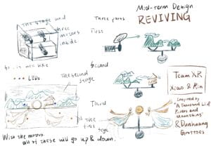
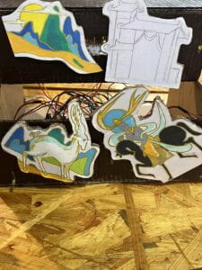
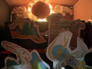
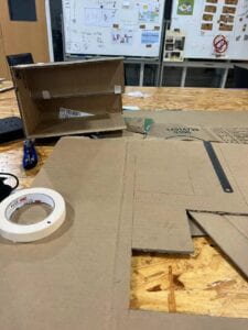
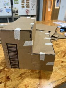
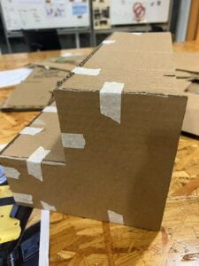
I designed a stage including the first and second floor so that the audience can have a better view of the whole contents. Thinking with Rin, we decided to use motors and light sensors to finish the project, as we want to use light sensors to control motors to move so that the characters can move like it is alive. Then, we thought it was good to let the deer and king on the first floor and the background on the second floor. We used cardboards to build as it was easy to make and we could paint on easier than other materials. Here are some photos about the stage.
FABRICATION AND PRODUCTION
After having a basic frame, we started to write codes with help of Steve and build circuits:
#include <Stepper.h>
const int stepsPerRevolution = 200; // change this to fit the number of steps per revolution
// for your motor// initialize the stepper library on pins 8 through 11:
Stepper myStepper(stepsPerRevolution, 8, 9, 10, 11);void setup() {
// set the speed at 60 rpm:
myStepper.setSpeed(60);
// initialize the serial port:
Serial.begin(9600);
}
//
void loop() {
// step one revolution in one direction:
Serial.println(“clockwise”);
myStepper.step(stepsPerRevolution);
delay(500);// step one revolution in the other direction:
Serial.println(“counterclockwise”);
myStepper.step(-stepsPerRevolution);
delay(500);
}
const int LIGHT_SENSOR1_PIN = A0;
const int LIGHT_SENSOR2_PIN = A1;
const int LIGHT_SENSOR3_PIN = A2;
const int LED1_PIN = 3; // Arduino pin connected to LED’s pin
const int LED2_PIN = 5;
const int LED3_PIN = 11;
const int ANALOG_THRESHOLD = 500;
bool runChecker = false;
unsigned long timePrevious = 100000;
bool runChecker2 = false;
unsigned long timePrevious2 = 100000;
int brightness = 0; // how bright the LED is
int fadeAmount = 20; // how many points to fade the LED by#include <Servo.h>
Servo servo;
int d = 500;
void setup() {
Serial.begin(9600);
pinMode(LED1_PIN, OUTPUT); // set arduino pin to output mode
pinMode(9, OUTPUT);
pinMode(LED2_PIN, OUTPUT); // set arduino pin to output mode
pinMode(10, OUTPUT);
pinMode(LED3_PIN, OUTPUT); // set arduino pin to output mode
pinMode(13, OUTPUT);
}// variables will change:
int analogValue;void loop() {
analogValue = analogRead(LIGHT_SENSOR1_PIN); // read the input on analog pin
delay(100);
Serial.println(analogValue);
if(analogValue > ANALOG_THRESHOLD) {
analogWrite(LED1_PIN, brightness);
// change the brightness for next time through the loop:
brightness = brightness + fadeAmount;
// reverse the direction of the fading at the ends of the fade:
if (brightness <= 0 || brightness >= 100) {
fadeAmount = -fadeAmount;
}
// wait for 30 milliseconds to see the dimming effect
delay(30);
servo.attach(10);
if (runChecker == false) {
timePrevious = millis();
runChecker = true;
}
if (millis()-timePrevious<1000) {
servo.write(60);
Serial.println(‘a’);
}
if (millis()-timePrevious>1000 && millis()-timePrevious<2000) {
servo.write(120);
Serial.println(‘s’);
}
if (millis()-timePrevious>2000) {
runChecker = false;
}
}
else {
digitalWrite(LED1_PIN, LOW); // turn off LED
}
analogValue = analogRead(LIGHT_SENSOR2_PIN); // read the input on analog pin
delay(100);
Serial.println(analogValue);
if(analogValue > ANALOG_THRESHOLD) {
analogWrite(LED2_PIN, brightness);
// change the brightness for next time through the loop:
brightness = brightness + fadeAmount;
// reverse the direction of the fading at the ends of the fade:
if (brightness <= 0 || brightness >= 100) {
fadeAmount = -fadeAmount;
}
// wait for 30 milliseconds to see the dimming effect
delay(30);
servo.attach(10);
if (runChecker == false) {
timePrevious = millis();
runChecker = true;
}
if (millis()-timePrevious<1000) {
servo.write(60);
Serial.println(‘a’);
}
if (millis()-timePrevious>1000 && millis()-timePrevious<2000) {
servo.write(120);
Serial.println(‘s’);
}
if (millis()-timePrevious>2000) {
runChecker = false;
}
}
else {
digitalWrite(LED2_PIN, LOW); // turn off LED
}analogValue = analogRead(LIGHT_SENSOR3_PIN); // read the input on analog pin
delay(100);
Serial.println(analogValue);
if(analogValue > ANALOG_THRESHOLD) {
analogWrite(LED3_PIN, brightness);
// change the brightness for next time through the loop:
brightness = brightness + fadeAmount;
// reverse the direction of the fading at the ends of the fade:
if (brightness <= 0 || brightness >= 100) {
fadeAmount = -fadeAmount;
}
// wait for 30 milliseconds to see the dimming effect
delay(30);
servo.attach(13);
if (runChecker == false) {
timePrevious = millis();
runChecker = true;
}
if (millis()-timePrevious<1000) {
servo.write(60);
Serial.println(‘a’);
}
if (millis()-timePrevious>1000 && millis()-timePrevious<2000) {
servo.write(120);
Serial.println(‘s’);
}
if (millis()-timePrevious>2000) {
runChecker = false;
}
}
else {
digitalWrite(LED3_PIN, LOW); // turn off LED
}
}
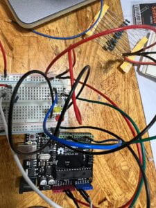
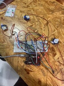
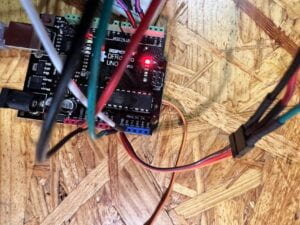
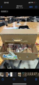
Also, I began to paint the characters.
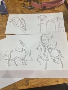
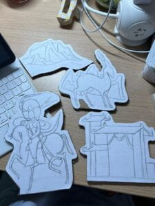
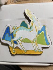
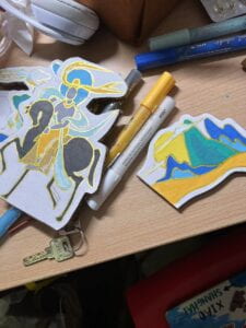
All things were really complex but finally all things went well.
During the whole process, I went through a lot and also learned a lot.
Some mistakes:
- We used light sensors in the Arduino box, which have differences between positive and negative poles. As usual, we thought the longer side would be the positive side and the shorter one would be the negative. However, it turnt out that we were wrong because the sensors did not work. In the end, we found this and corrected this mistake.
- As the motors worked in a really fast way that the cardboards always fell down, Rin changed codes a lot about the numbers of the codes. Meanwhile, we also thought about changing to a bigger motor which can be easier to control. But we finally found that bigger motors may cause more complex codes and situations, so we continued to use the little blue motors.
- As the cardboard of the background on the second floor is so heavy for the little motor, here came two problems: the first one was that the disk on the motor was always inclined, so I used some rheostats to put on weight so that it could be balanced. And the second one was, because the motor loaded too much so that it turned to be really hot to melt the glue, so I used the adhesive plaster to settle it.
- When I started to build the third circuit, there was an accident. As I connected 2 LEDs directly to the 5V power by mistake, it burnt. It was really scary so I paid much attention to connecting in the following processes.
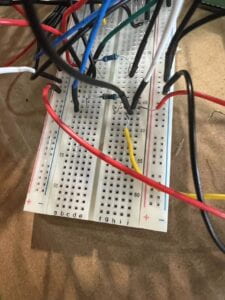
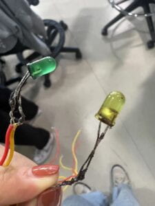
As for the user test, it was unfavorable as we only made the circuits at that time. Compared to others’ good projects, I felt upset but motivated as I think my project and topic was meaningful and I could make it!
Improvement:
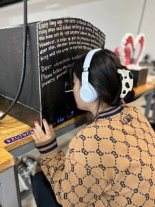
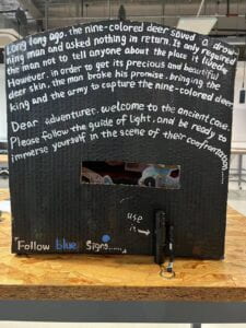
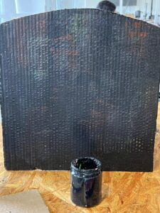
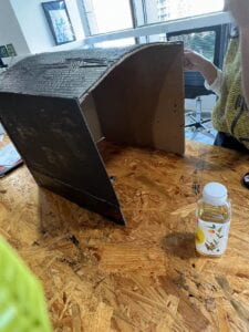
- Based on Rudi’s suggestions, we built a cave and used the flashlight as the user’s tool, which can be more interactive and exciting.
- Inspired by the group project, we also added music while users are exploring.
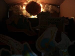
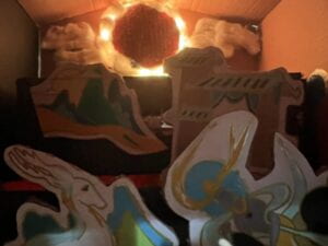
- I used type lights to make a sun so that the atmosphere in the cave will be more magical and historical.
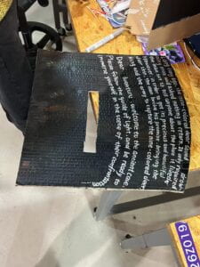
- In order to make users have a better understanding of our background and how to start exploration, I wrote the conclusion of the story and some matters should be paid attention to on the surface of the cave.
CONCLUSIONS
Just as I mentioned in the beginning of the report, I wanted to move the wall paintings out of the cave and make them more digital so that they can exist forever. This is really what I want to do. In the performance, we guided the user to use the flashlight to follow the blue signs. If the light sensors feel the lights, the motors will begin to work and the characters will seem like they are alive. I thought the audience were interested and appointed with the project as everyone seemed to have a passion for contents inside the cave. After the class, one of the assistants came to us and she told us that she was proud and happy of us, as in the user test, we only had cardboard and circuits, but now we gave out such an entire project. All in all, I am satisfied with my project. Also, if there is more time, I think there are also many things that can be improved, such as: characters can be more movable; an entire story can be told instead of just a part of that and so on. During this tired but meaningful project, I really learned a lot and I believe that it will be better next time ! Here are final videos and pictures of the project.
